|
|
|
|
|

|
|
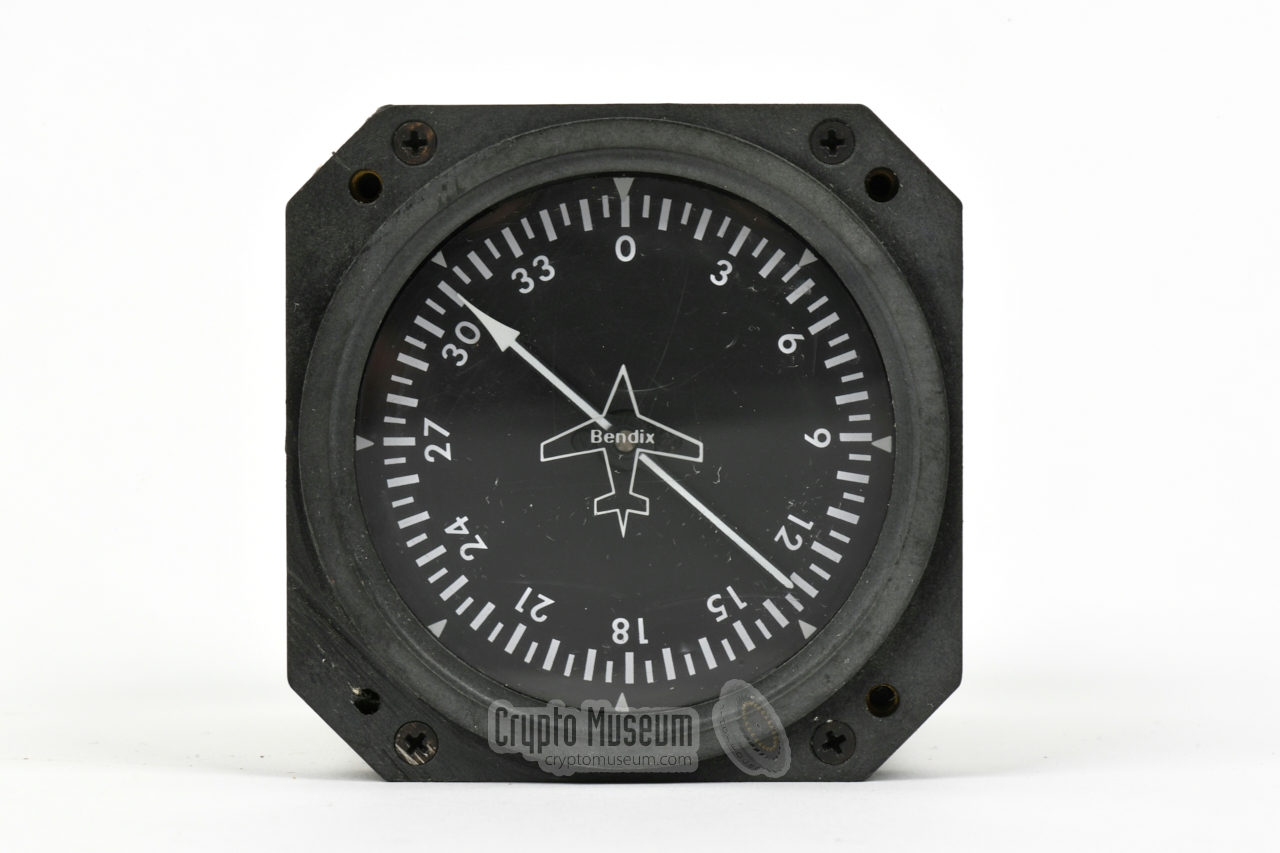
The Bendix ADF-T12B and C models, are basically transistorized versions
of the old valve-based Motorola ADF-12.
The device was succeeded by the digital ADF-T12D, which had
thumbwheels to set the frequency, but was
mechanically far less reliable than its analogue predecessors.
|
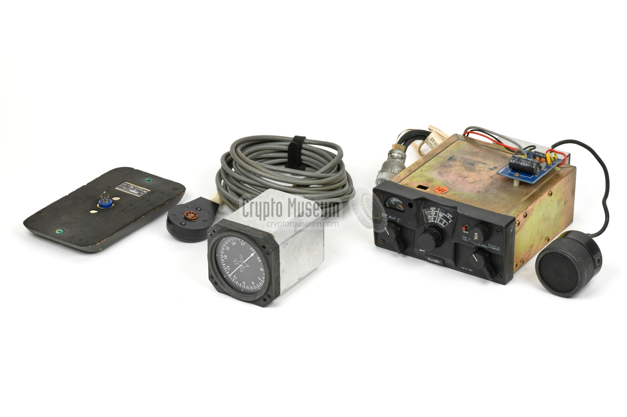
The diagram below provides an overview of the controls at the front panel
of the receiver. At the bottom left is the MODE selector, which also acts as
the power switch. At the right is a 3-position band selector. At the centre
is the tuning scale, with the tuning knob immediately below it. At the top left
is the signal strength meter (S-meter), which can be used as an aid for
optimally tuning to the desired radio beacon (or clandestine radio station,
when used as a law enforcement tool).
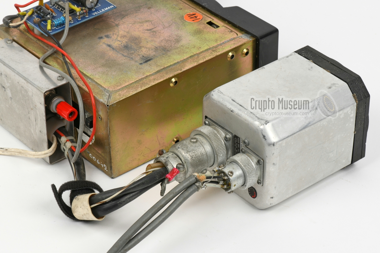
All connections are via a
16-way Amphenol connector at the rear, that mates
with a receptacle inside the metal cradle that holds the receiver.
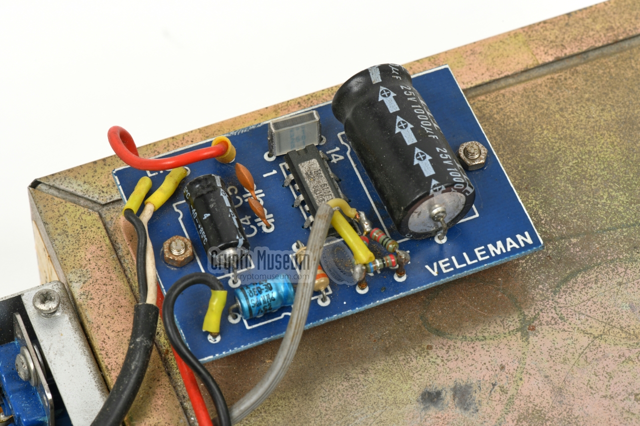
The cradle is wired to an external audio amplifier
– here in the form of a self-built Velleman kit –
and to a 9-pin connector – shown here at the left – that is fitted to the
rear
of the visual indicator. The fixed loop antenna is also
connected to the rear
of the indicator via a
4-pin Cannon connector.
The sense antenna is connected directly to the PL-259 socket at the
rear of the cradle.
|
|
|
Radio Monitoring Service
RCD
|
|
|
|
In the 1970s and 80s, the Netherlands was flooded with clandestine radio
stations – also known as pirates – that operated in the regular
broadcast radio bands, in between legal radio stations.
In particular the FM broadcast band (87-108 MHz) and the MW band
AM were popular at the time.
|
As clandestine
transmitters cause interference with legal stations and do no pay
for the use of the frequency spectrum, it was the duty of the
Radio Controle Dienst (RCD) — at the time part of
the state-owned telecom provider PTT — to locate them and enforce
the telecom regulations.
To do this effectively, the RCD had a series of unobtrusive cars
— initially Ford Granadas —
in which a 19" equipment rack was installed
on the co-seat, as shown in the image on the right.
The indicator and receiver of the
ADF-T12 are visible at the top left.
The speaker is at the right edge.
|
|
|
The angle of incidence of the intercepted radio signal, is
measured by applying the signals of the
two perpendicular loop antennas
to a servo-controlled RF-resolver inside the indicator, to find
the angle of minimum signal strength (null).
It is basically a Bellini-Tosi goniometer
driven by a servo-motor.
The motor is controlled by an error signal provided by the receiver,
and stops when the null is reached. As there are two nulls (displaced by 180°),
the sense antenna is used to find the correct one, by controlling
the rotational direction of the servo-motor.
|
|
|
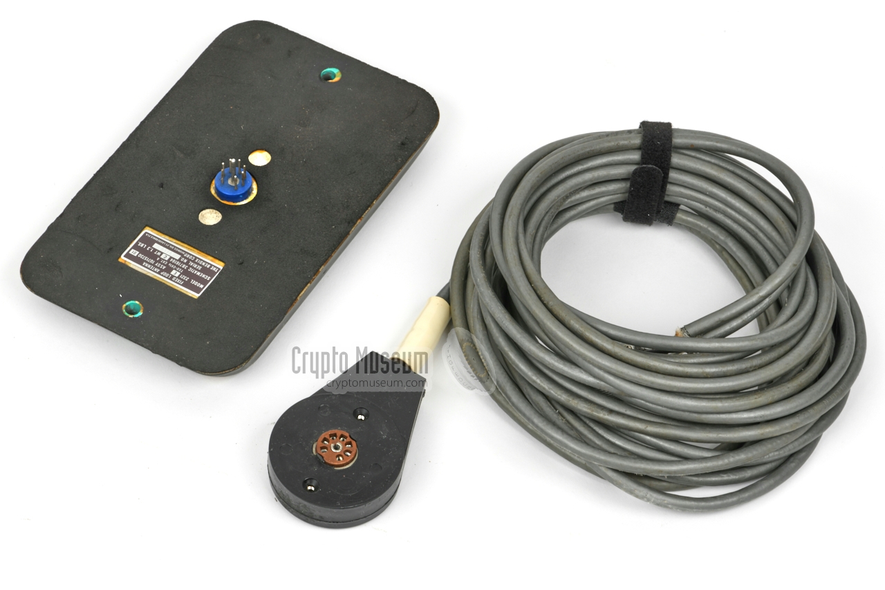
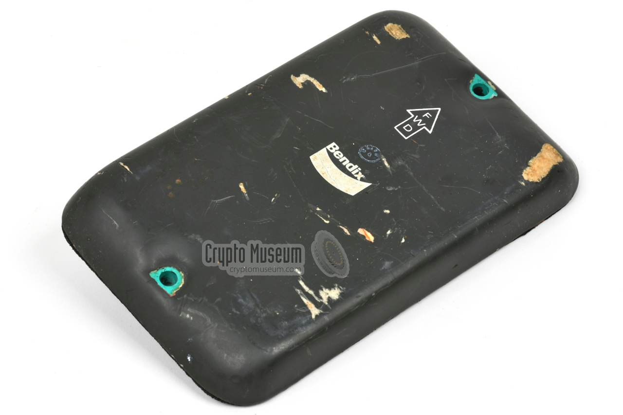
One of the unique features of the ADF-T12 is the so-called fixed
loop antenna, that allows the angle of incidence to be measured
automatically.
It consists of two perpendicular loop antennas, wound
around a flat ferrite body, potted in a strong weather resistant
compound. The loop antenna is connected to the indicator via
two cables (one for each loop). Inside the indicator is an RF-resolver
(goniometer)
of which the rotor coil is connected to the input of the receiver.
|
|
|
A sense antenna should be connected directly to the receiver,
to resolve the 180° ambiguity of the loop antenna (and the servo
system). By looking at the phase difference between the signal from the
sense antenna and the (delayed) signal from the loop antenna (via the RF resolver),
the servo is driven in the correct direction.
The sense antenna is also used when the device is used
for the reception of regular broadcast transmissions in the
MW radio band.
|
|
|
In order to get an acoustic feedback of the intercepted
signal, an (optional) external amplifier was available,
such as the original Model 102A/B amplifier. It amplifies the line signal
from the receiver to speaker level.
In the Netherlands however, the RCD used a low-cost
amplifier kit from Velleman, and mounted it on top of the
cradle.
|
|
|
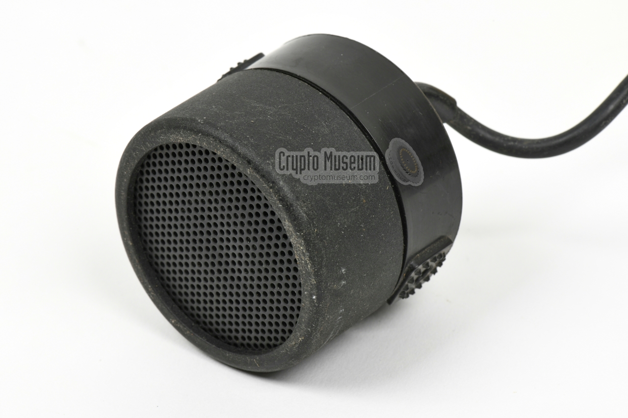
In the Netherlands, the RCD used a standard cylindrical speaker
from the German peripheral manufacturer Peiker, the same one
as was commonly supplied in the 1970s and 80s with the mobile
radios of the emergency services, and with the first generation
of mobile (car) phones.
The speaker has a diameter of 58 mm and was usually embedded in
the front panel of the equipment rack inside the
intercept vehicle.
|
|
|
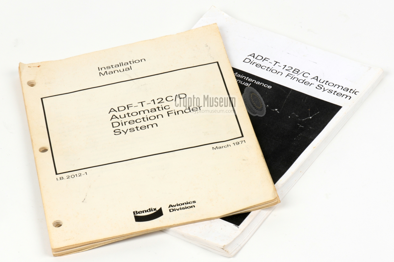
Two manuals are available for the ADF-T12-C: (1) an installation manual
and (2) a maintenance manual. Both are available for download
below.
The manuals describe the operating principle of the direction finder
and shows how it should be installed in an airplaine. It also shows how
the loop antenna should be installed and calibrated.
➤ Installation manual
➤ Maintenance manual
|
|
|
Below is the simplified block diagram of the system, in which only part
of the receiver
is shown at the top right. For clarity, the tuning sections
and the IF stages have
been omitted. At the bottom left is the
indicator with the servo-controlled RF resolver. The two loops
of the loop antenna,
are connected to the two static windings of the
RF resolver. The rotor coil of the resolver is fed to the receiver,
where it is amplified, delayed by 90° and then mixed with a 47 Hz
reference signal that is provided by the indicator.
The resulting signal is added to the signal from the sense antenna.
Once the receiver is tuned to the desired frequency,
its audio output is fed back to the indicator, where the
47 Hz component is extracted from the audio signal and fed to a
balance amplifier that compares the phase of the 47 Hz signal from the receiver
with the phase of the 47 Hz signal from the reference oscillator.
The result is used to drive the servo-motor. As soon as the needle points
to the angle of incidence,
the error signal from the RF resolver is null and the servo-motor stops.
|
The block diagram of the bare receiver is shown below.
At the left is the sense antenna, of which the signal is amplified in an
RF amplifier (RF). It is then mixed with the signal from a Variable Frequency
Oscillator (VFO) and amplified in three stages (IF1, IF2, IF3). This signal is
then used to feed the Automatic Gain Control (AGC), which avoids overloading
on strong RF signals. It is also fed to an AM detector, after
which the audio signal is amplified in three stages (AF1, AF2, PA).
On receiver 201 models B, B1 and D, a Beat Frequency Oscillator (BFO) is
present for CW reception.
The section at the left, where the error signal from the loop antenna is
injected, has been omitted here for clarity. The 47 Hz signal, injected by the
reference oscillator of the servo system, is taken from the first audio stage
(AF1) and fed back to the indicator,
where it is part of the servo loop.
|
|
|
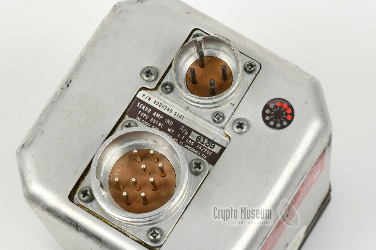
Servo amplifier-indicator
|
|
|
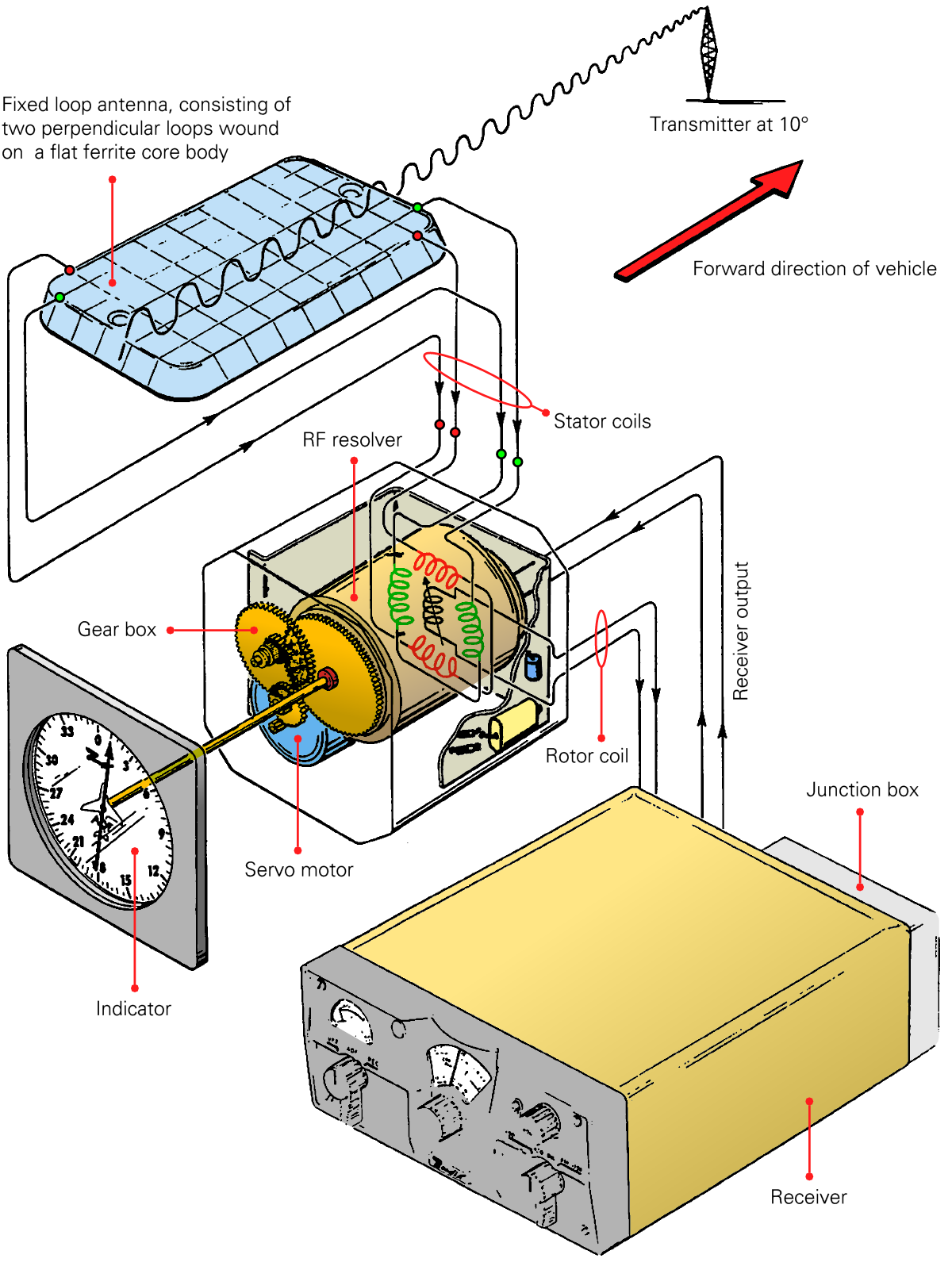
The drawing below was taken from the installation manual [A], and explains
how the servo system works. For clarity, the various parts have been coloured.
The signals from the two loops inside the loop antenna, are connected
to the stator coils of the RF resolver (red, green),
which is in fact a Bellini-Tosi goniometer.
The rotating coil of the RF resolver is connected to the receiver.
A separate 47 Hz signal from a reference oscillator inside the servo/indicator,
is also fed to the receiver (not shown here). The audio output from the receiver
is fed back to the servo/indicator, where its phase is compared with the
original signal from the reference oscillator, and used to drive the
servo-motor.
The latter drives the RF resolver (and the indicator) via a gear box.
|
The principle of the Bellini-Tosi Goniometer
(RF resolver), is illustrated below.
North (N) represents the forward direction of the vehicle.
The loop antenna consists of a rectanglular
flat ferrite body, with two separate windings at 90° angles, shown
in red and green respectively.
One winding (red) is responsible for the north/south (N/S) magnetic field
of the intercepted signal (H). The other winding (green) picks up the
west/east (W/E) component of the magnetic field.
The two antenna windings are connected to the corresponding stator fields
of the RF resolver (goniometer). The rotating part of the goniometer,
i.e. the rotor coil, picks up the fields from the N/S and W/E stator coils,
and is connected to the input of the receiver. It is rotated
by the servo-motor (under control of the receiver output) until a
signal minimum (null) is found.
|
|
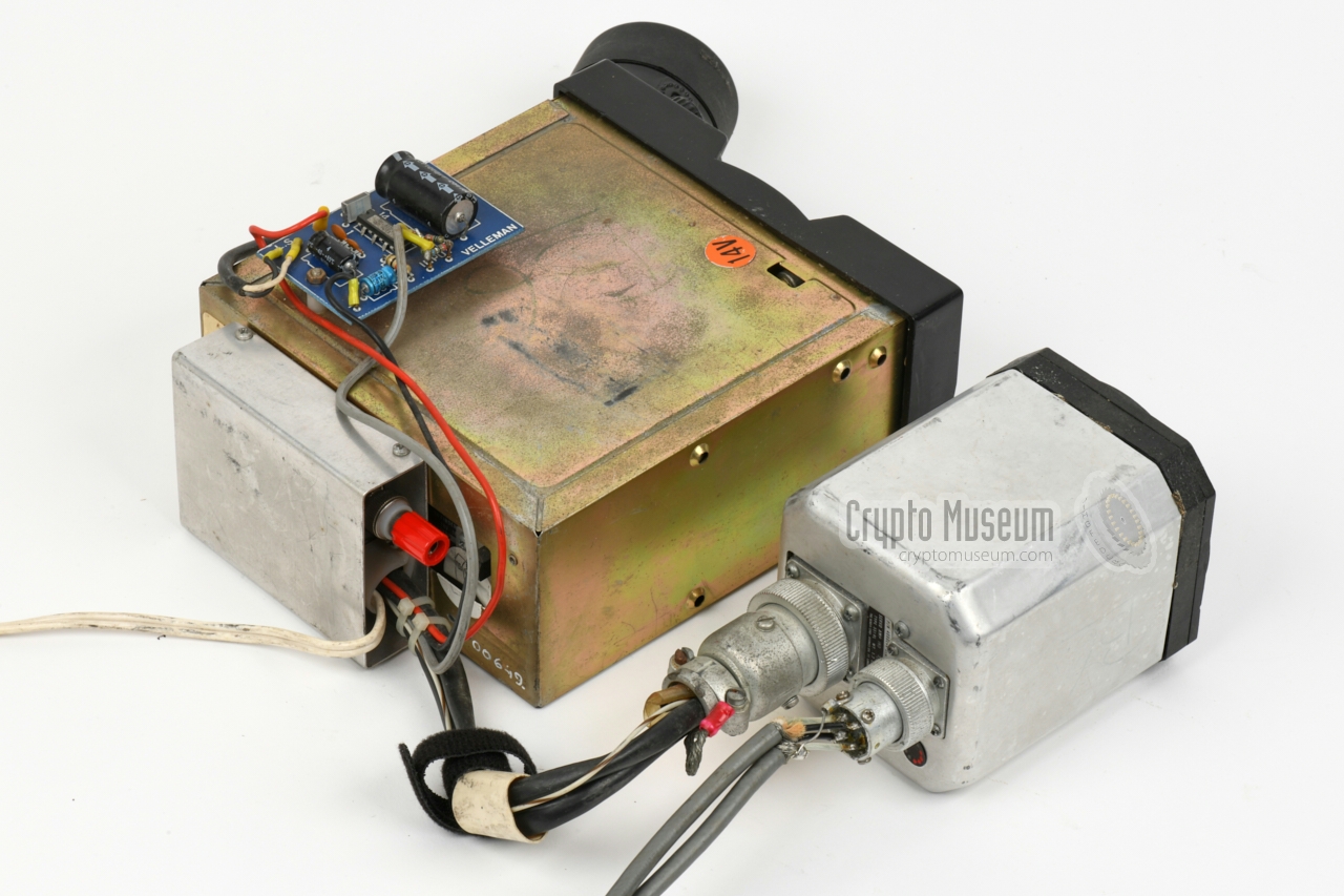
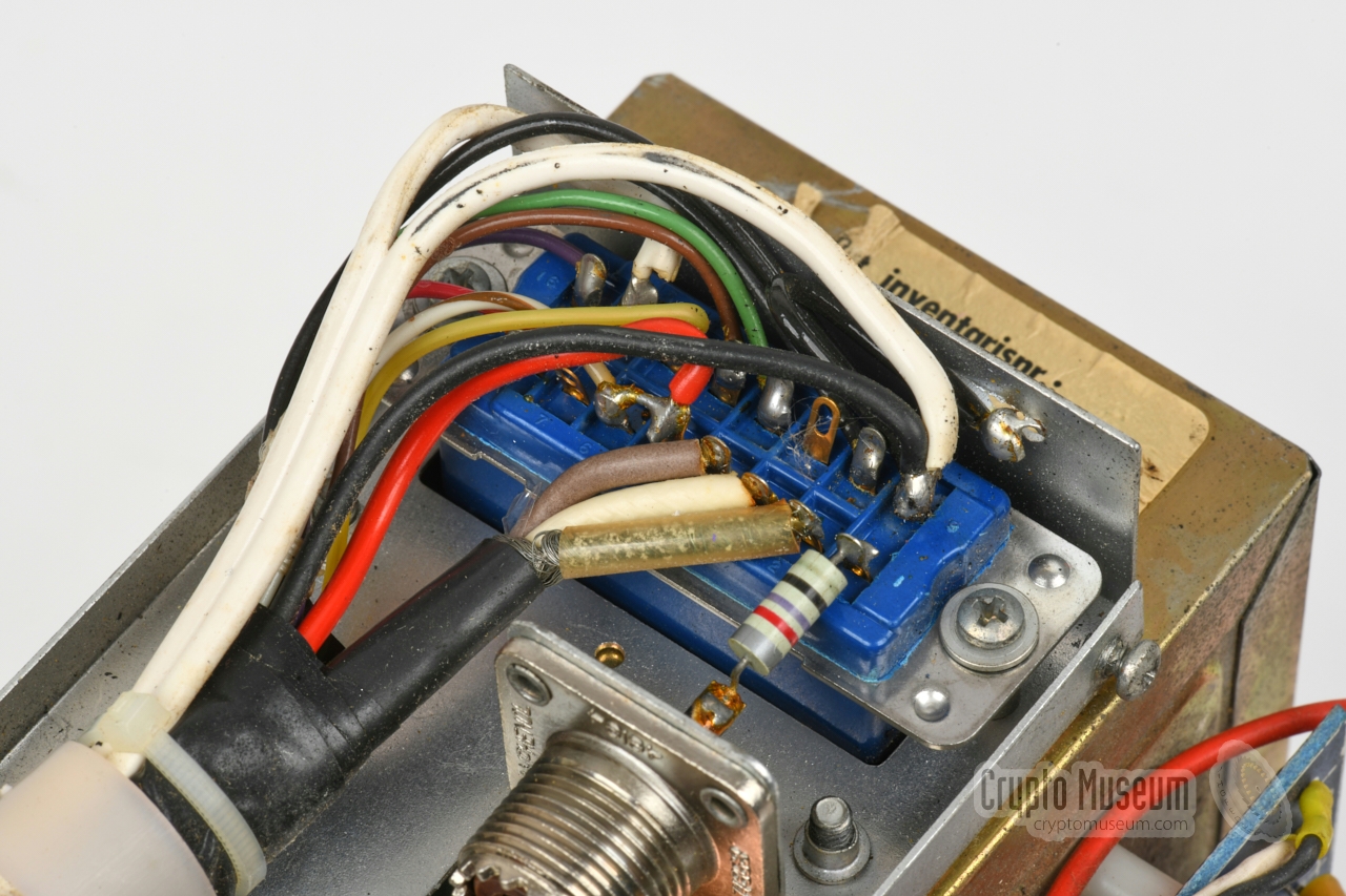
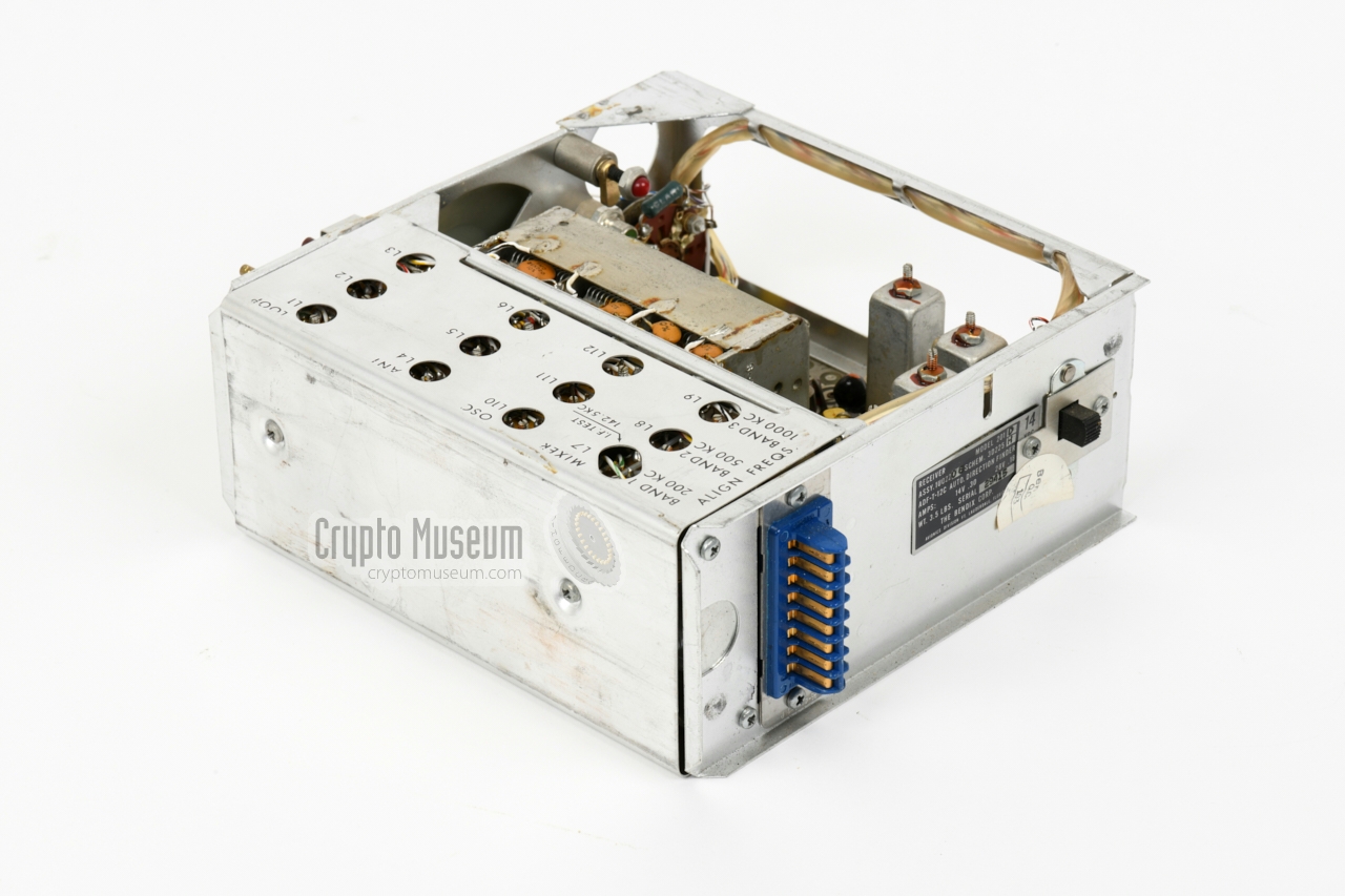
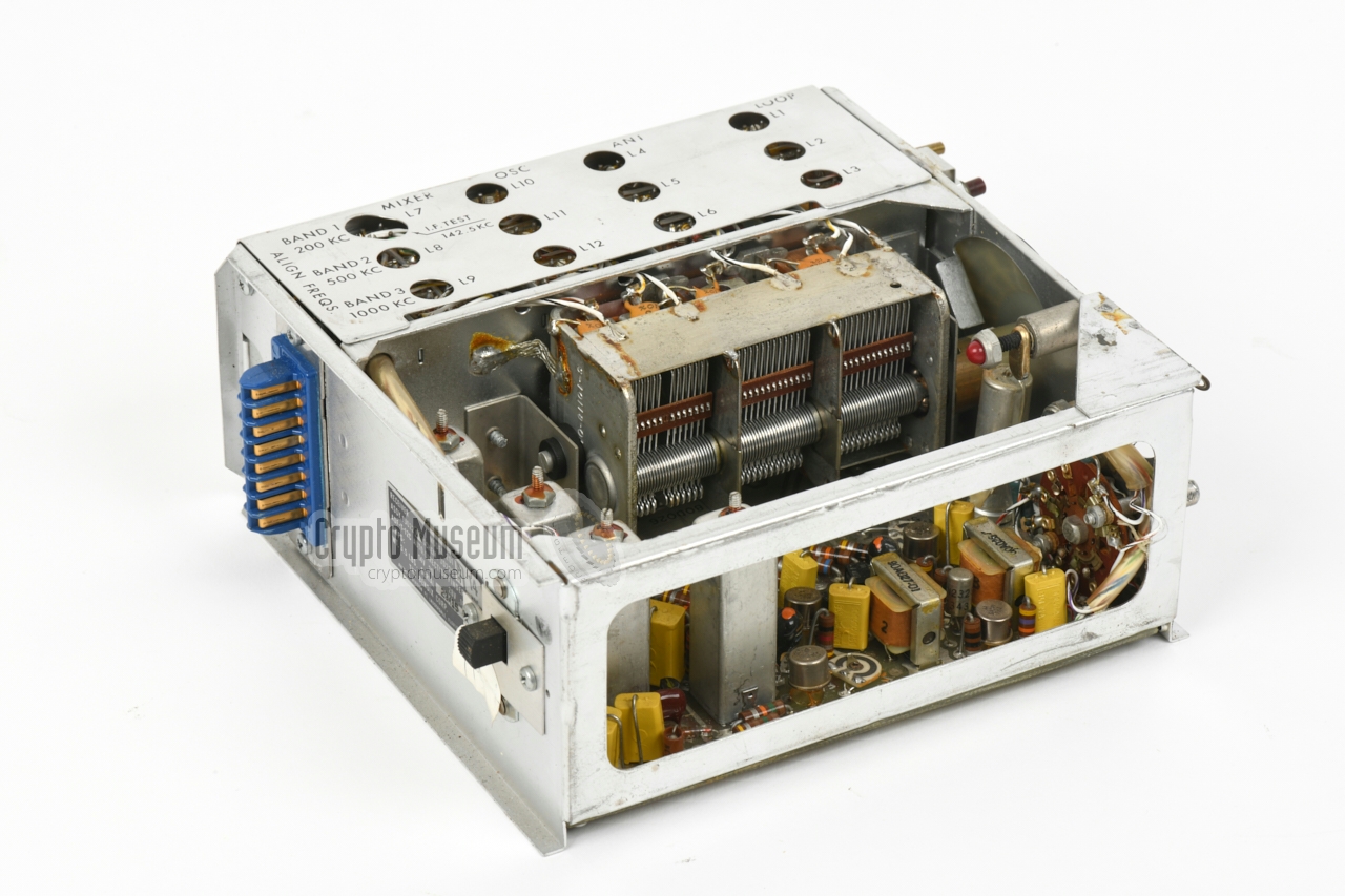
Getting access to the interior of the 201 Receiver is straightforward.
When it is installed in the cradle, 1 which is usually the case,
it can be removed by releasing the locking bolt
– accessible through a hole in the front panel –
after which the receiver
can be pulled from the metal cradle.
|
As the receiver is connected to the outside world via a single
16-way connector at the rear,
there is no need to disconnect any of the wires
before opening it. The image on the right shows the bare receiver after
it has been taken out of the cradle and the front panel has been removed.
The device consists of a molded aluminium frame with a large printed circuit
board (PCB) at the bottom. All parts are mounted on the PCB.
At the centre is a large 3-way tuning capacitor
that controls the Local Oscillator (VFO) as well as
the tuned circuits of the RF input stages in tandem.
|
|
|
|
The right part of the frame is taken by the tuned circuits of the Local
Oscillator, the antenna input circuits and the mixer, with separate adjustments
for each of the 3 frequency bands.
Adjustment of the receiver is possible by temporarily using a
service cable to connect it to the cradle. 1
|
-
In the Bendix documentation, the cradle is referred to as the wiring harness.
|
When we acquired our ADF-T-12C in December 2020, it had not been used for
at least 30 years. Nevertheless it worked first time and only required minor
– prodominantly cosmetic – work on the exterior. On the inside,
the tuning scale – which was corroded –
was carefully cleaned , and the glass of the S-meter had
to be refitted, for which the instrument had to be partly disassembled.
The following restoration work has been carried out:
|
- Exterior cleaned
- Meter glass repaired
- Tuning scale repaired (was heavily corroded)
- Front panel and knobs cleaned
- Knobs refitted
- Power connection restored
|
|
|
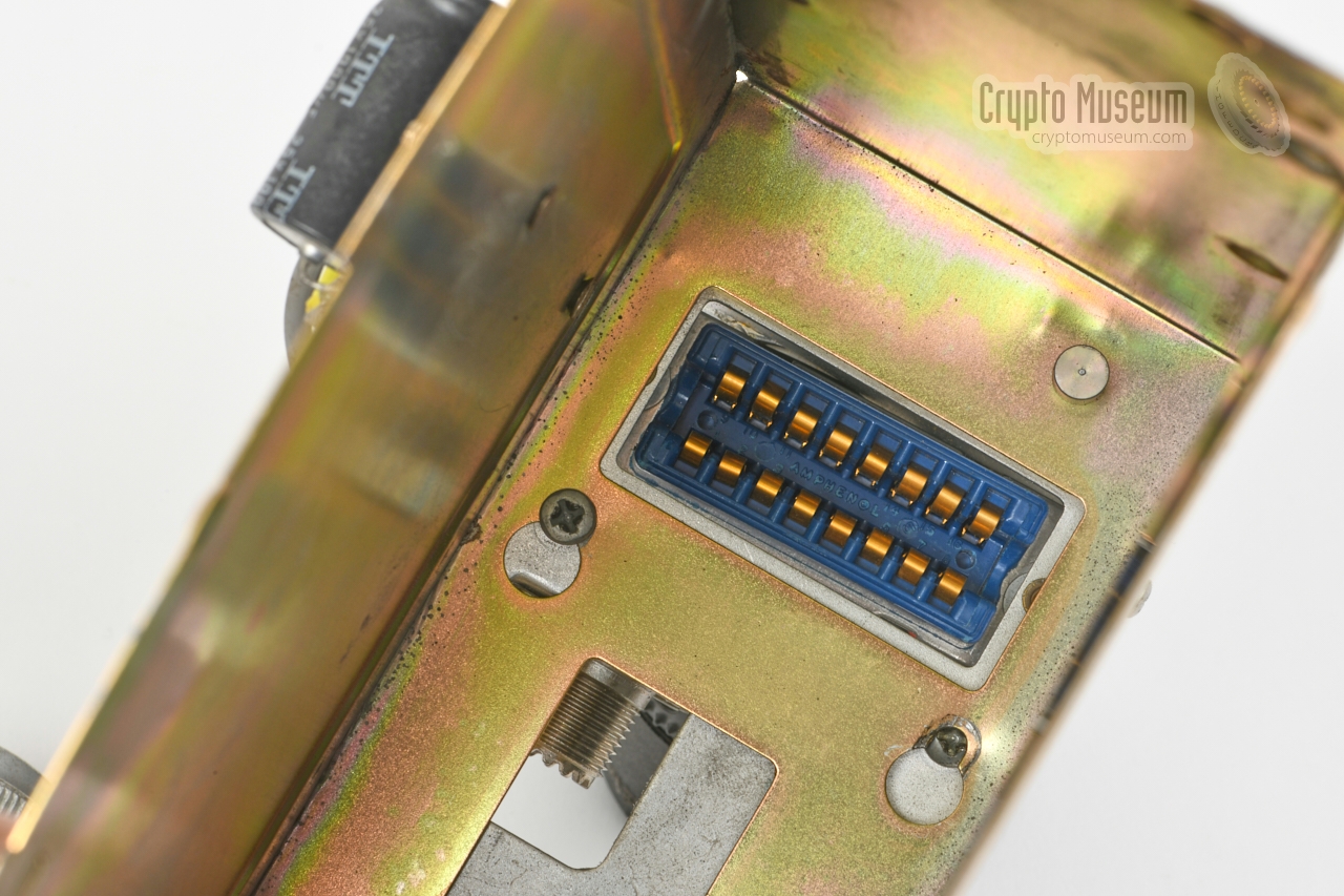
Amphenol Blue-Ribbon connector
|
|
|
|
Below is the pin-out of the 16-way Amphenol connector at the rear of the
receiver, when looking onto the contacts. This is the same as looking at the
solder side of the receptacle. Note that only the receiver has to be powered
by an external 12V DC source. Any connected peripheral, gets its DC
power from the receiver.
Full wiring diagram on the last page of the
installation manual [A].
|
- Sense antenna
- Loop shield
- Loop input R1 (tin)
- Loop input R2 (copper)
- Optional Audio Amplifier A
- Dial lamps
- Tuning meter (ext)
- 47 kHz switching phase 2
- Ground
- Servo DC output
- Spare
- 47 kHz switching phase 1
- Servo DC output
- Headset (500Ω)
- DC in (+)
- ADF Servo signal output
|
|
|
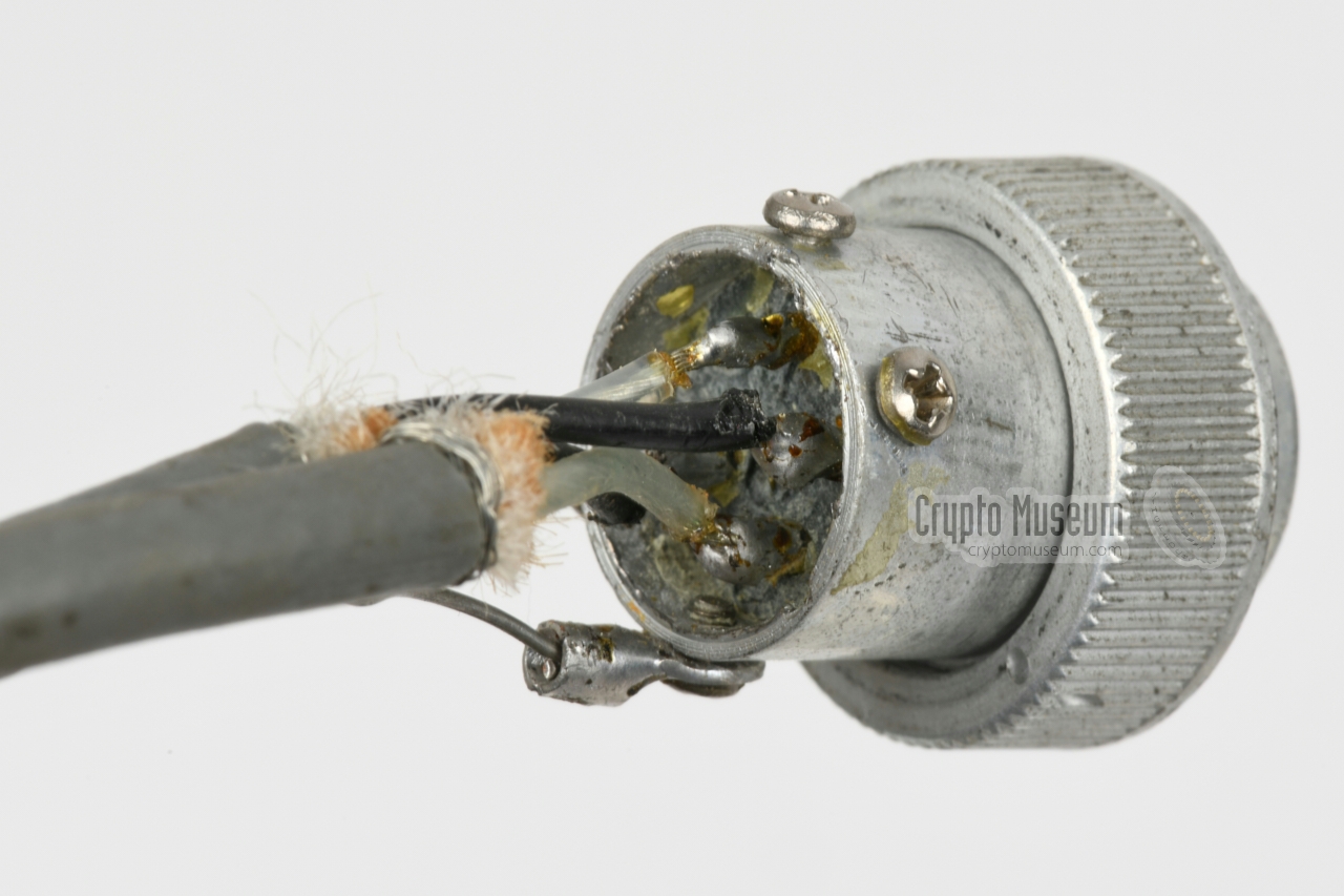
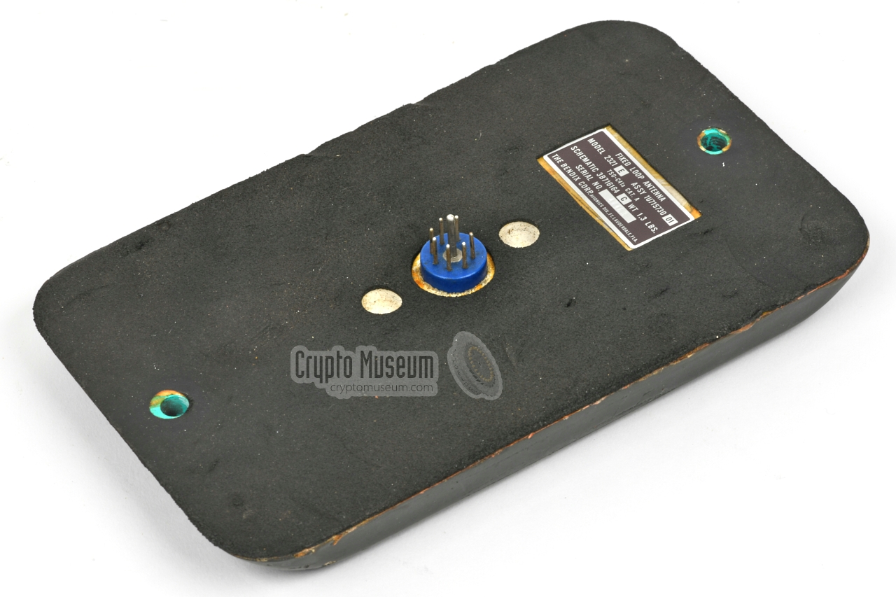
The loop antenna has a 7-pin male connector at the bottom, that mates
with a rather special female cable part that came with the antenna. It has
two fixed 2-wire shielded cables – one for each of the loops – that should be
connected to the indicator (rose) by means of a
Cannon WK 4-21C-5/8 connector.
This 4-pin connector is also know by its Bendix part number S-240611-11.
Below is the pinout when looking into the receptacle at the
rear side of the indicator.
|
Frequency 190-1750 kHz Bands 3 (see below) Modulation AM, MCW, CW IF 140 kHz Sensitivity (ADF) 75µV, (REC) 10µV Selectivity 4 kHz (-6dB), 12 kHz (-60dB) Output 70 mW, 500 Ω Response 200-2000 Hz (10dB) Settling 7 seconds (max.) Accuracy ±3° Power 12 or (28V) (selectable on the rear panel) Current Receiver: 100 mA (170 mA), Indicator: 120 mA (60 mA) Dimensions 212 x 159 x 71.5 mm Weight Receiver 1588 g, Indicator 771 g
|
|
The device covers a frequency range from 190 to 1750 kHz,
spread over three bands:
|
- 190-440 kHz
- 420-900 kHz
- 850-1750 kHz
|
- 210D Receiver
- 2321E loop antenna
- 551-series servo indicator
|
- Cor Moerman, Personal correspondence
December 2020.
|
|
|
|
Any links shown in red are currently unavailable.
If you like the information on this website, why not make a donation?
© Crypto Museum. Created: Saturday 17 December 2016. Last changed: Wednesday, 05 November 2025 - 11:59 CET.
|
 |

|
|
|