|
|
|
|
|

|
|
USSR Cipher Rotor
Meteorologic cipher machine
- wanted item
M-130, codenamed KORALL (Russian: КОРАЛЛ) 1 is an electromechanical
rotor-based cipher machine,
developed around 1965 at NIIA
(Russian: НИИА, now Avtomatika) in Moscow
(Russia). The device is a numbers-only machine, and was used in the countries
of the former USSR
and the Warsaw Pact for the distribution of encrypted
weather reports.
In East-Germany (DDR) it was known as Koralle.
In 2010 and 2011, Crypto Museum was able to investigate a surviving
M-130 machine in Austria.
This page is based on that research, complemented by
other sources [2][3].
|
The M-130 is built on the chassis of an existing teleprinter,
which was also used as the basis for the
CM-1 (Vasilek)
[4].
Although the original one had an alpha-numeric character set,
a modified version — with numbers only — is used here [2].
This was sufficient for encryption and decryption of
meteorologic data which is numeric by nature.
The image on the right shows a typical M-130 machine ready for use.
It came with a matching 24V PSU.
The keyboard contains a single row of keys with the numbers 0 thru 9,
plus the letter 'X', a minus-sign (-) and a carriage return key.
|
|
|
A space is automatically inserted after each fifth number
(the usual 5-number groups).
A useful side-effect of using a numbers-only cipher machine, is that it is
language-independant. If letters are converted to numbers first,
the machine can be used for any language in the world.
This is also why the contemporary M-125 (Fialka)
machine had a lever to switch between letters (30) and numbers (10).
The M-130 was also available in a non-crypto version
(i.e. as a bare teleprinter).
It is currently unknown how many M-130 units were produced, but
judging from the surviving serial numbers
(assuming that they are
contiguous) it seems likely that between 100 and 200 units were made.
Note that most machines were supplied as a bare teleprinter (base only),
and that the cipher units (and rotors) were issued separately, albeit with
a matching serial number. 2
|
 |
-
KORALL (КОРАЛЛ) is the Russian word for coral.
In German it is known as Koralle.
-
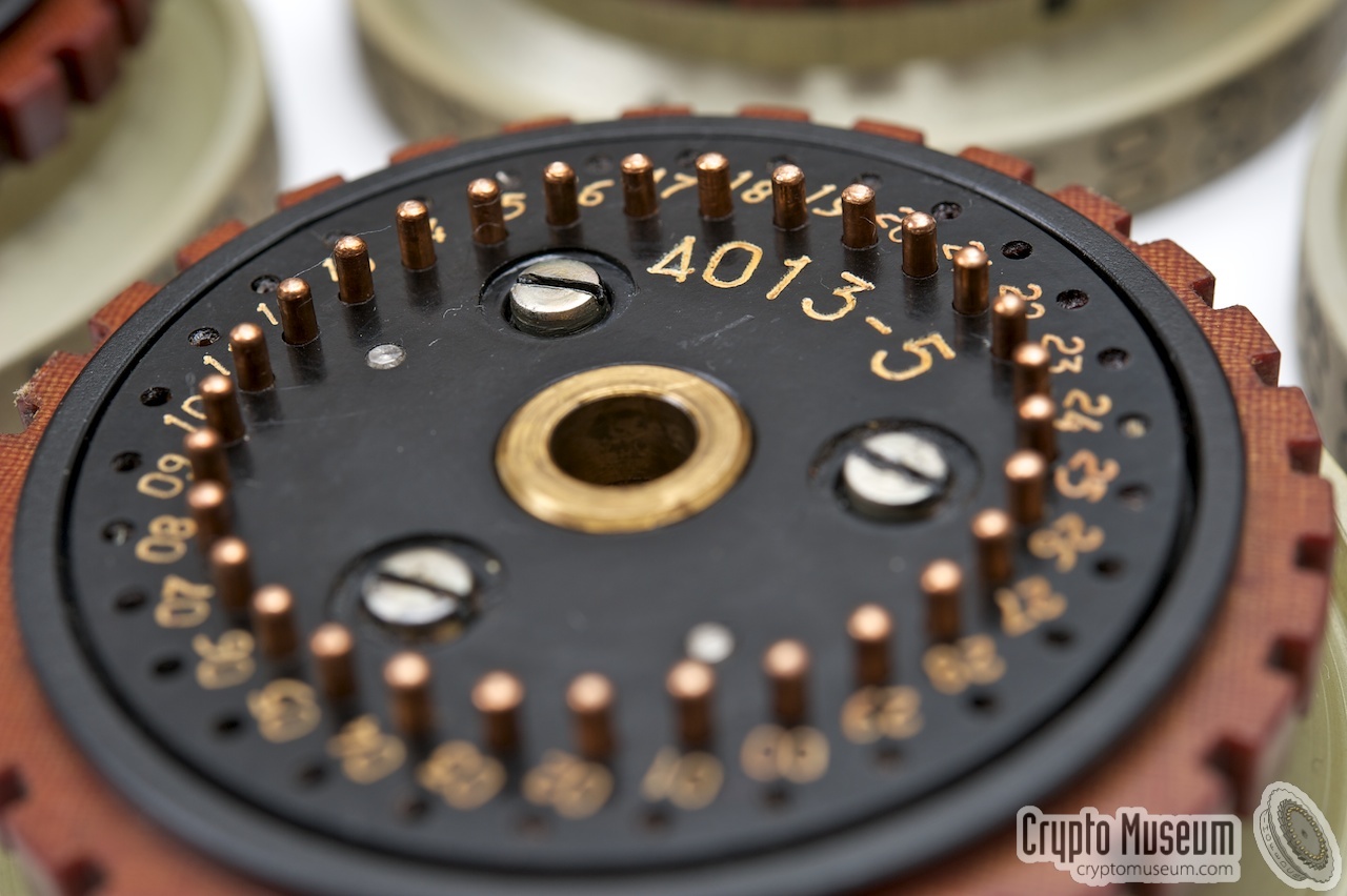
The cipher unit is extremely rare. So far, we've seen only one
(S/N 4013). There are however several rotor sets amoung collectors,
some of which carry the serial numbers of known bare base machines.
This suggests that there might also have been cipher units for these machines.
➤ More
|
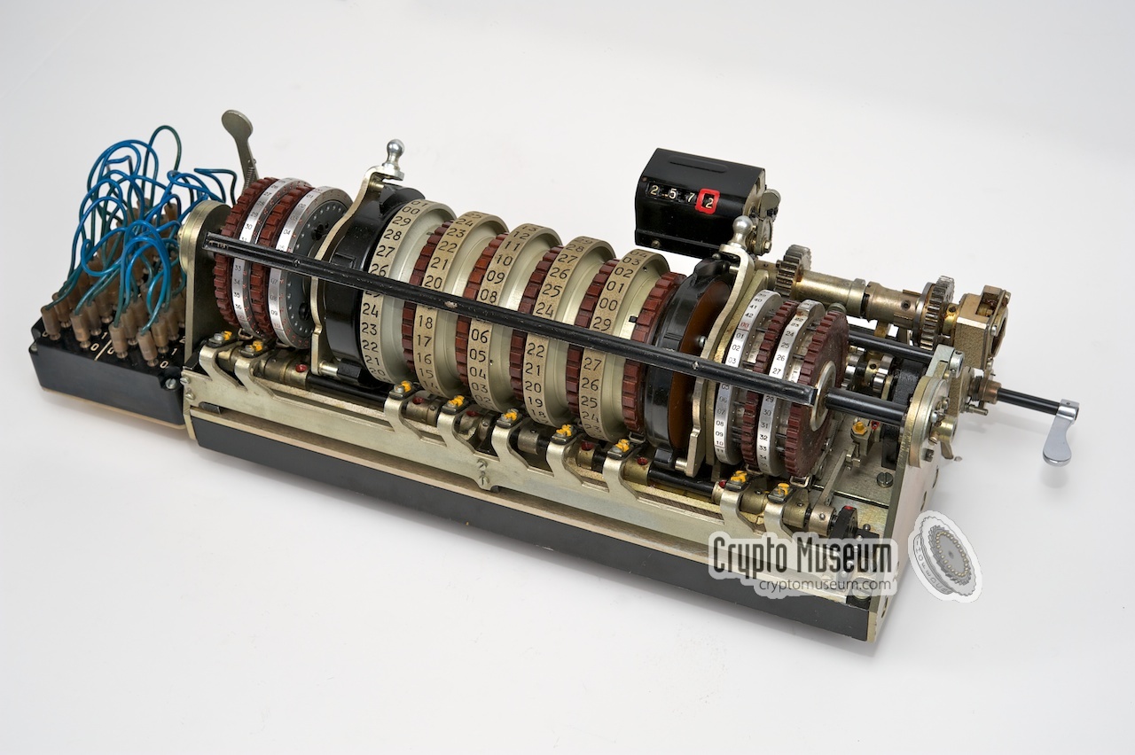
The image below provides a quick overview of the features of the M-130.
The machine consists of a base unit (the bare numeric teleprinter)
and a removable cipher unit that holds the cipher rotors, the stepping
rotors and the plugboard.
|
|
The M-130 can be used in three different modes: coding, decoding and
plain text. The desired mode of operation is selected by means of a
large rotary knob
at the right front of the machine, known as the
MODE-selector. The three settings are marked with the Russian letters
О, З
and Р.
|
| Label | Russian | Phonetic | English |
|
|
| О | Открытый Текст | Otkrytyj Tekst | Plain text |
| З | ЗашифроватЬ | Zashifrovat | Cipher |
| Р | РасшифровыватЬ | Rasshifrovyvat' | Decipher |
|
|
Just behind the MODE-knob is another rotory 3-position rotary selector of which
the function is currently unknown. It is likely that this knob control the
operation of the printer and/or the tape puncher.
If you have any further information about this, please contact us.
|
| Label | Russian | Phonetic | English |
|
|
| К | |
|
|
| КП | |
|
|
| П | |
|
|
|
During the Cold War,
the Soviet Union (USSR)
and its Warsaw Pact allies
used a variety of cipher machines, including the
M-125 (Fialka). The use of these devices for direct
communication between the Warsaw Pact states however, was strictly
forbidden. Each country had its own set of rotors (each wired differently)
and the machines were often adapted to the local language.
In the case of war, the Warsaw Pact states would need to have quick access
to accurate weather reports. For this they did not want to depend on existing
(NATO) sources, as these were likely to be unavailable to them.
As a solution, a Warsaw Pact-wide network of Meteorologic Services
was created. They had the task to independantly collect all necessary
meteorologic data from a variety of sources and create a reliable
weather prediction from that.
Furthermore, they had to develop ways to circumvent possible (radio)
interference — also known as jamming — by the enemy.
|
Once complete, the weather report would be shared between the contributing
states.
As it was likely that the meteorologic data was further distributed
within each country via other cipher systems –
for example with the M-125 Fialka) –
it was necessary to encrypt the weather report, or else
it could be exploited by an evesdropper as a
crib (a piece of known plaintext).
This was done with the M-130 (KORALL), shown here with the front lid open.
In order to improve the cryptographic strength, separate pin-wheels were used
to control the irregular stepping.
|
|
|
In the former DDR (East-Germany), this service was known as the
Meteorologischer Dienst (MD) der Luftstreitkräfte/Luchtverteidigung
(LSK/LV), abbreviated MD der LSK/LV [3].
They used the M-130 to share the weather report with
the Main Command Post (Hauptgefechtsstand, HGS) and the Air Defence
Departments of the other Warsaw Pact countries.
As there was a contemporary voice encryption device that was also
named Koralle,
the M-130 was sometimes nicknamed the Wetterkoralle.
The first DDR cipher operators were trained on the M-130 in Moscow in 1966 [3].
|
| |
East-German meteorologic bunker HGS-14
|
The diagram above shows the meteorologic bunker of the East-German command
post HGS-14, as it was in 1980.
The M-130 was located in the K-room, 1
a small annex of the Weather Information Service of Duty
(DWIZ).
Besides the operational M-130, the room also contained a spare
M-130 unit plus the key-sheets.
A cipher operator with sufficient security clearance could only
enter this room after collecting the key from the DWIZ.
A more detailed descripton (in German) can be found on the
internet site of the former Zentrale Flugwetterwarte
(ZFWW) [3].
In the DDR, The M-130 was planned to be replaced in 1985 by its
successor — the M-131 — but according to several eyewitnesses this
never happened, possibly because of the rapidly changing political
situation at the time. In 1989, the Berlin Wall fell and a year later
East-Germany (DDR) was reunited with West Germany.
|
|
-
'K' might refer to KORALLE or KRIPTO.
|
Although the construction of the cipher unit might look similar to that of
the German Enigma machine of WWII,
or the contemporary M-125 (Fialka), its operation is
quite different. Both Enigma and Fialka have an entry disc at one end, and a
reflector at the other end. The M-130 however, does not have a reflector.
Instead, a character comes in at one end and leaves the cipher unit
at the other end.
The double patch panel (at the left) can be used to alter the order of the
lines to both static discs (ED1, ED2). The simplified block diagram
of the M-130 is as follows:
The 10 lines from the keyboard (0-9) are first scrambled by the the leftmost
patch panel (plug board) and then fed to the leftmost entry disc (ED1).
The current then passes the 5 cipher rotors, until it hits the rightmost
entry disc (ED2).
As each rotor has 30 contacts (rather than just 10), 20 contacts are looped
back (much like a reflector). This principle is known as re-entry
or re-injection. Eventually, after one or more passes, the current
leaves the rightmost static disc (ED2), passes the second patch panel (PB2) and
activates the printer and/or the tape puncher.
In order to allow the same rotor-settings to be used for decryption, the entire
unit can be reversed (electrically), by operating the large
MODE-selector at the right front of the machine.
This switch has three settings: encrypt (З), plaintext (О)
and decrypt (Р). In plaintext mode (О), The input is connected
directly to the output. In encryption mode (З), the system works as
described above. In decryption mode (Р), the input and output wires are
swapped.
➤ Download the complete circuit diagram
|
|
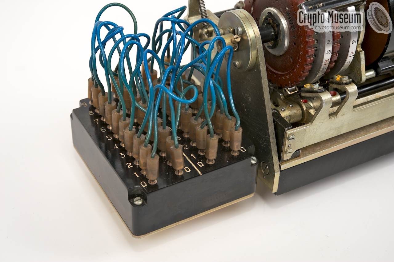
In order to add extra complexity to the system, a double patch panel is present.
This works much like the plug board (Steckerbrett) of
an Enigma machine.
However, unlike the enigma – where the wires were swapped in pairs –
the M-103 is single-ended and allows any cross-connection.
This increases the key space and avoids the self-reciprocity of the
Enigma Steckerbrett.
|
In addition, the M-103 has in two plug boards instead of one,
which allows the entry and exit
wires to be swapped independently. This adds another layer of complexity,
and increases the cryptographic strength of the cipher.
The image on the right shows the double patch panel, which is mounted to the
left of the cipher unit.
It is wired to the rest of the unit at the bottom.
A white line divides the patch panel in two.
The left half controls the wiring to the
leftmost static disc (ED1), whilst the right half is connected to the rightmost static disc (ED2).
|
|
|
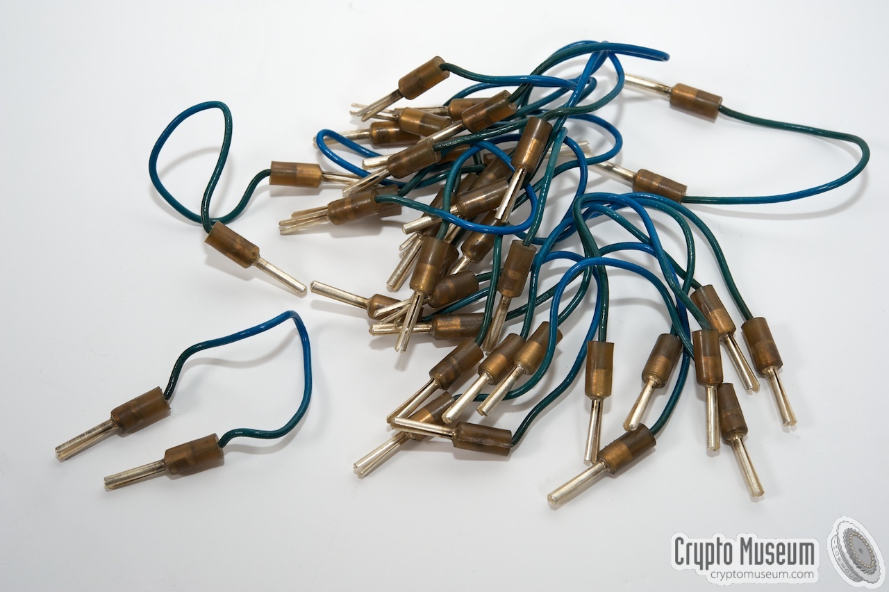
The patch panel is configured by 20 short blue patch cables,
each with a plug at either end. All 10 cables must be present on each half of the patch
panel, and the cable may not be connected between the two halves.
Configuring the patch panel was part of setting the cryptographic key.
|
|
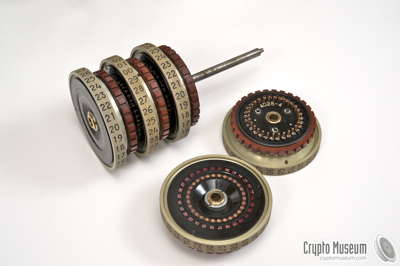
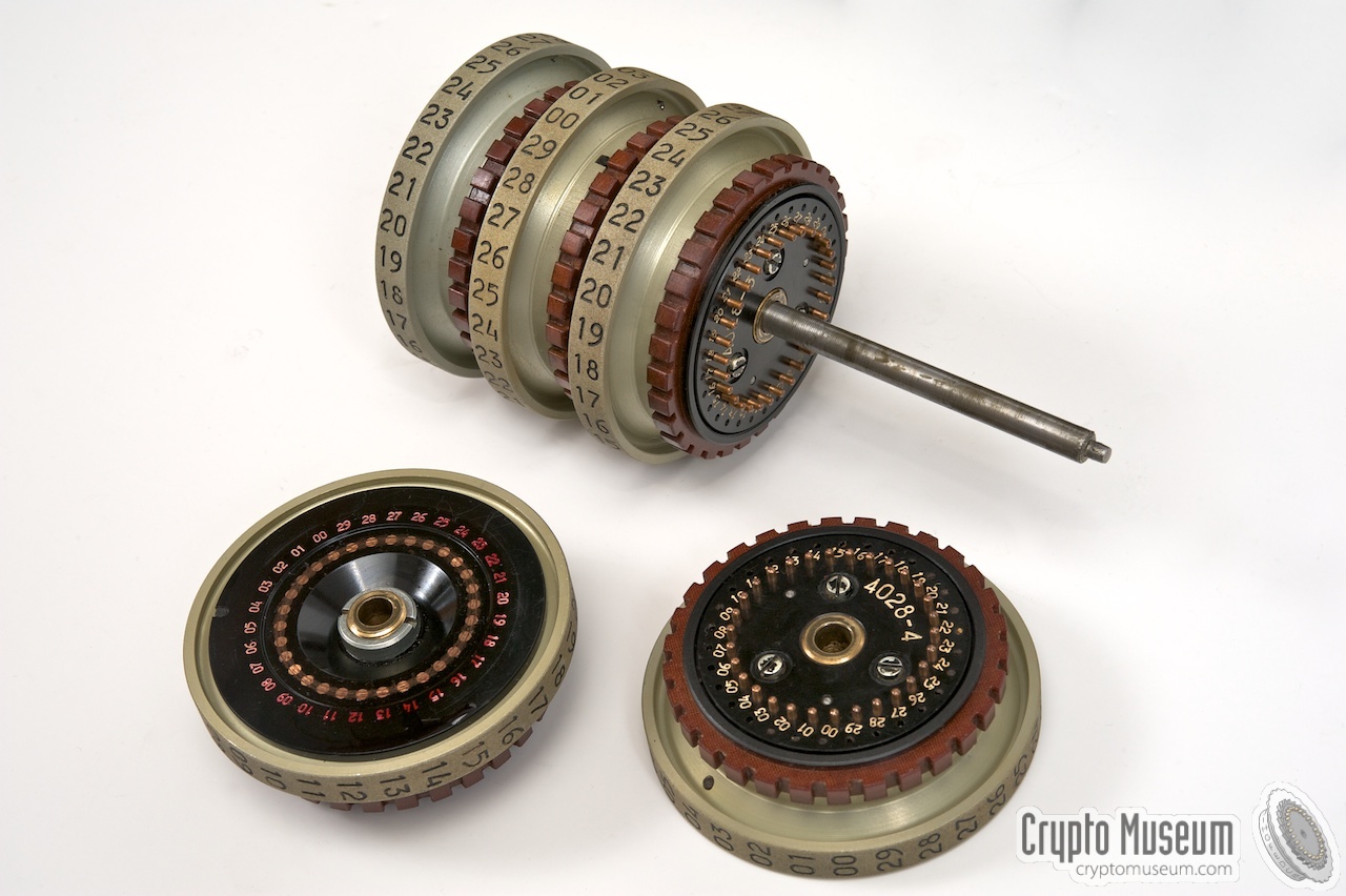
The M-130 has five cipher rotors, each with 30 contacts at either side.
The 30 flat-faced contacts at the left side are wired in a randomized manner
to the 30 spring-loaded contacts at the right. The reason why each rotor has
30 contacts rather than just 10, is that the same rotors were also used with
other Russian cipher machines of the era, like the CM-1 Vasilek
[4].
|
As we only need 10 contacts (for the numbers 0-9), the remaining contacts of both
static discs are wired as a reflector, much like the UKW, or Umkehrwalze,
of an Enigma machine.
As a result, the electric current may be reflected several times until it finally
leaves the static disc at the other end (see the block diagram above).
The image on the right shows the five cipher rotors after removing them from the
cipher unit. Rotors 1, 2 and 3 are still on the shaft, with rotors 4 and 5 in front
of them. Rotor number 5 is showing its flat-faced contacts.
|
|
|
A coding disc can be at any position on the shaft,
allowing a total of 120 different rotor orders.
Just like the starting position of each rotor, this was part of the
daily key settings (see below). As an extra encryption layer, it was also
possible to rewire the cipher rotors in the field.
|
|
The table below shows the wiring of the cipher rotors when they were rediscovered
in 2010. Note that the rotors can easily be rewired in the field, so there is no
guarantee that this wiring is valid. However, all five rotor sets there were
found at the time, had the same wiring.
|
| ID | 00 01 02 03 04 05 06 07 08 09 10 11 12 13 14 15 16 17 18 19 20 21 22 23 24 25 26 27 28 29 |
|
|
| 1 | 18 13 26 00 07 11 15 22 23 24 16 05 06 01 17 12 25 02 03 10 08 09 04 29 27 19 14 21 28 20 |
| 2 | 03 01 17 00 19 14 18 10 08 27 04 20 09 28 29 24 22 02 21 13 23 15 25 11 06 16 26 12 07 05 |
| 3 | 27 25 26 15 19 02 09 13 17 12 01 05 24 28 14 00 04 11 21 22 29 03 16 08 18 07 20 06 10 23 |
| 4 | 21 07 11 12 13 17 18 25 23 00 19 20 27 16 05 24 01 08 03 28 26 15 22 14 09 10 29 06 04 02 |
| 5 | 18 16 17 09 04 14 21 07 08 03 28 23 00 19 20 15 25 11 27 10 05 06 01 02 12 13 29 24 22 26 |
|
Two stepping rotors, or pin-wheels,
are mounted at either side of the cipher rotors.
Each one has a different number of segments, and pins at different positions.
The mechanical construction of the cipher unit is such, that
each stepping rotor can only be used in one location.
The order of the stepping rotors should be: 1 and 2 to the left of the cipher
rotors, 3 and 4 at the right.
Note that the black numbering at the circumference of the rotor is
different from the red numbering printed at the right side.
A sharp cut-out in the circumfere is used when setting the rotors
to their neutral position (00). A notch on the zeroize axle will
catch this cut-out when the reset lever is engaged (see below).
|
| ID | Steps | Notches | Notch positions |
|
|
| 1 | 37 | 14 | 02 04 05 08 11 15 16 21 23 24 28 32 33 36 |
| 2 | 31 | 11 | 01 04 07 08 11 15 18 19 22 24 28 |
| 3 | 43 | 14 | 03 07 10 11 12 15 24 28 30 33 37 38 39 42 |
| 4 | 41 | 16 | 01 03 07 09 12 13 14 16 18 19 21 25 29 33 35 38 |
|
The M-130 features irregular rotor stepping. This is different from most
Enigma machines (which feature regular stepping), but very similar
to the contemporary Russian M-125 (Fialka).
Another thing which the M-130 has in common with the M-125, is
that adjacent rotors move in opposite directions. In the diagram below,
we've numbered the positions of the cipher rotors (left to right) from 1 to 5.
Rotors 1, 3 and 5 move up,
whilst rotors 2 and 4 move down (seen from the front).
The middle rotor (3) always makes a single step upwards on each key press.
The outer two rotors (1 and 5) also move up, but only when they are driven
by stepping rotors 2 and 3 respectively.
Rotors 2 and 4 move down, but their stepping is
controlled by stepping rotors 1 and 4.
The red arrows show the relation between the stepping rotors and the
cipher rotors.
A stepping rotor has stepping pins at arbitrary positions.
Each pin inhibits stepping of the corresponding cipher rotor.
|
The image on the right shows a close-up of the leftmost stepping rotors (1 and 2).
They can be removed by unlocking their axle with a pin at the left. Although the
order of the stepping rotors was never changed, the position of their pins could be
altered by a maintenance engineer.
Each stepping rotor has a different number of segments, or faces,
in order to maximise the period of the machine
(i.e. the number of steps before the sequence is repeated).
The number of steps on each stepping rotor is always a relative prime of the 30
contacts on each cipher rotor.
|
|
|
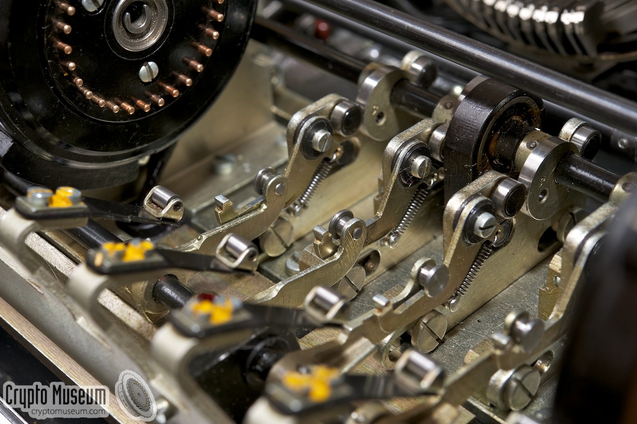
All stepping rotors make a single step on each key-press, and they
always move up (when viewed from the font). Whenever a pin is present at a
certain position on the stepping rotor, a
sensing lever below the rotor is pushed down.
This in turn pushes down a metal arm that disables the stepping of the
corresponding cipher rotor.
Movement of all rotors is controlled by a single axle located behind
the rotors. This is the so-called camshaft.
The timing of the machine is controlled by the position
of a series of cams on this axle, much like the camshaft of a car engine.
The illustration above shows the stepping mechanism viewed from the top of the
machine, after removing all rotors. The camshaft (C) is towards the top of the drawing.
The positions of the cams also control the stepping direction of each rotor.
It is clearly visible in the drawing above that the position of the stepping arms
of cipher rotors 2 and 4 is different from the rest.
The stepping rotors can be reset to their neutral position (00) by pusing a lever (R)
to the rear and using the crank (inserted at the right of the machine) until all
four rotors have stopped. This process is called zeroizing.
Pressing (R) in fact rotates the zeroize axle (Z) by several degrees.
As a result, four notches on this axle (N) will move forward and catch a cut-out
in the circumference of the stepping rotors (see above).
The crank should be operated until all stepping rotors are at 00.
|
|
Setting the cryptographic key was done in several stages, based on the so-called
key sheets. These were perforated paper blocks with the key settings for several
weeks in advance. Three different types of keys were marked:
|
- Patch key
- Weekly key
- Daily key
|
|
The patch key (1) defined the wiring of both patch panels
to the left of the cipher unit. It is currently unknown how often the patch key was
changed. The Germans called it the Decade Key, but this only refers to the number
of wires on each patch panel which is equal to a decade (10).
|
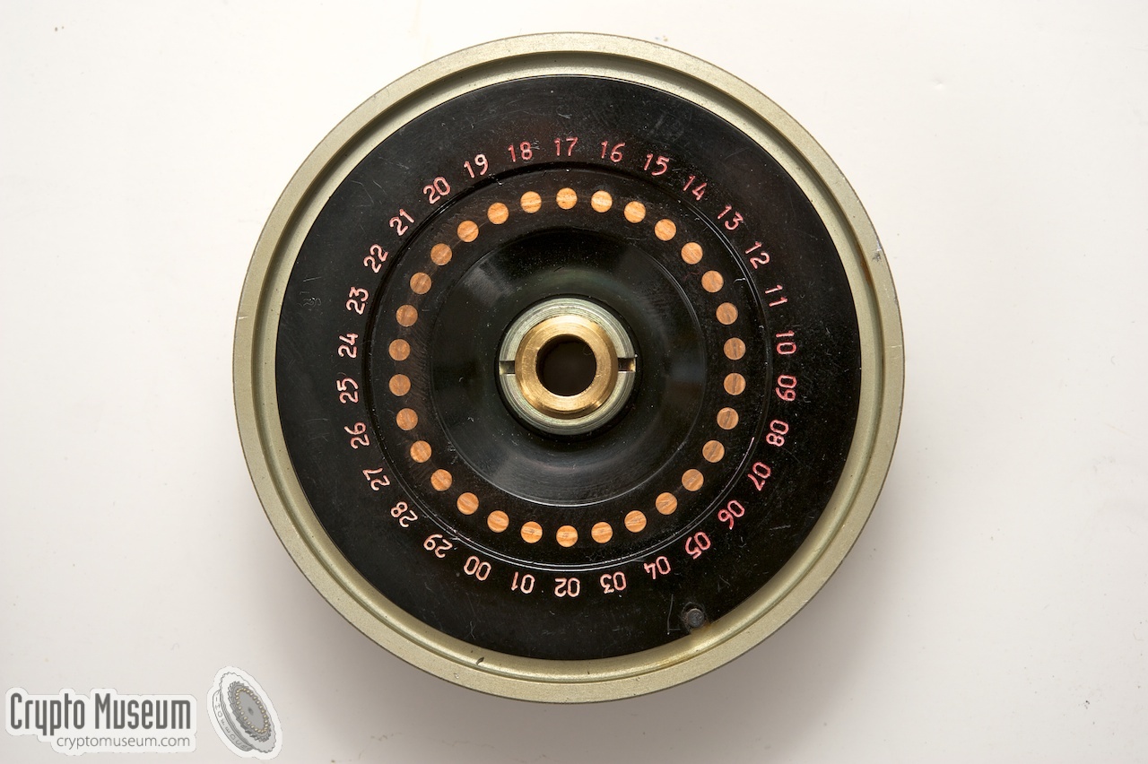
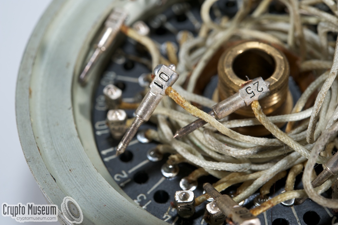
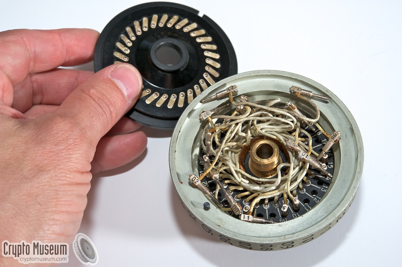
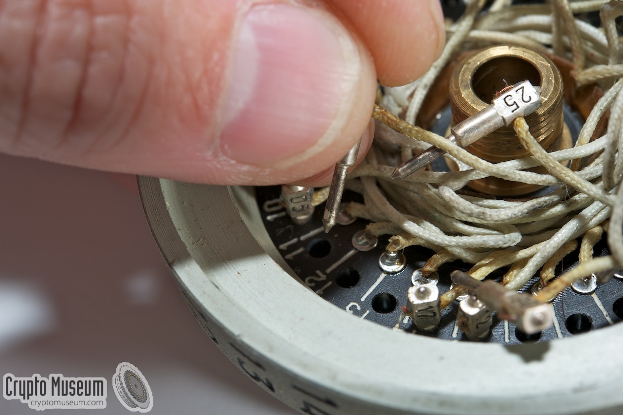
The weekly key consisted of rewiring each of the five cipher rotors. For that,
each rotor had to be opened and the internal wiring pins had to be reconfigured
carefully. This was a difficult task with many chances for making mistakes.
Inside a cipher rotor, each wire is soldered
directly to the rotor at one end, whilst the other end has a numbered pin.
This pin can be inserted in one of the numbered holes inside the rotor body.
The image on the right shows the interior of a cipher rotor, with pins 01 and 25
clearly visible. More detailed images below.
|
|
|
Once all cipher rotors are rewired, the rotors are closed and are then mounted on
the shaft in a prescribed order. It is currently unknown whether the rotor order
was part of the weekly key or whether it was changed daily.
Changing it daily, would certainly increase cipher security.
Before going live with freshly rewired rotors, the operator first had to check
whether the wiring was correct. This was done by encrypting two simple five-letter
groups (12345 67890) on the main machine and decrypting it on the spare one.
If the output matched, the wiring was assumed to be correct. If it failed, all five
rotors had to be disassembled and rewired again [3].
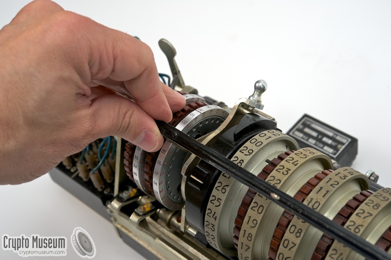
The daily key consisted of setting the start positions of the five cipher rotors.
The numbers on the key-sheet, e.g. 28 22 10 26 07 had to be aligned with a
metal ruler in front of the rotors.
It is currently unknown whether the stepping rotors at the sides were given a
unique starting position as well, or whether they were always restarted at 00.
It is possible that the rotor order was also part of the daily key.
|
|
Summarising, the following cryptographic variables can be set:
|
- Patch panels
- Rotor wiring
- Rotor order
- Start position of the cipher rotors
- Start position of the stepping rotors
|
Non-crypto version of the M-130
The M-130 was also available in a non-crypto version, which was in fact the
simple teleprinter it was based on. The exact model number of this
teleprinter is currently unknown, because it is not engraved on the type plate
of the surviving machines we have seen so far.
To discriminate it from the cipher machine, we've named it T-130
(as opposed to M-130 for the cipher machine).
|
The non-crypto version (T-130) was used for local weather reports (that did not
require encryption) and, more importantly, to relay encrypted weather
reports over long distances, where the intermediate operator(s) did not need
to know the contents or the nature of the message.
In the non-crypto version, the crypto-unit was replaced by a 'dummy' unit,
consisting of a metal plate with a connector. The contacts of the connector
were wired in such a way that the input to the crypto-unit was connected
directly to the output (simulating plaintext mode).
|
|
|
A non-crypto version could easily be converted into a full M-130, simply by
mounting a suitable crypto-unit instead of the dummy plate. The crypto-unit
would connect directly to the forementioned connector, and all data
was automatically re-routed through the crypto-unit.
The diagram above shows how relaying via simple non-crypto M-130 machines
might have worked for long-distance transmissions. At the left is the originator
of the report. The message (P) is encrypted with the daily key and then sent
(C) to the first station. As this station has a non-crypto version of the M-130
(called T-130 here), he can not decrypt it but simply passes it on (C)
to the next station and so on, until it finally reaches the M-130 at the
far end where it is decoded.
|
|
The M-130 is build on the chassis of an existing Russian teletype machine,
that was modified for the transmission of numbers only. The keyboard at the
front only contains the numbers 0 to 9, the letter 'X', a minus-sign (-) and
the carriage return key (CR).
|
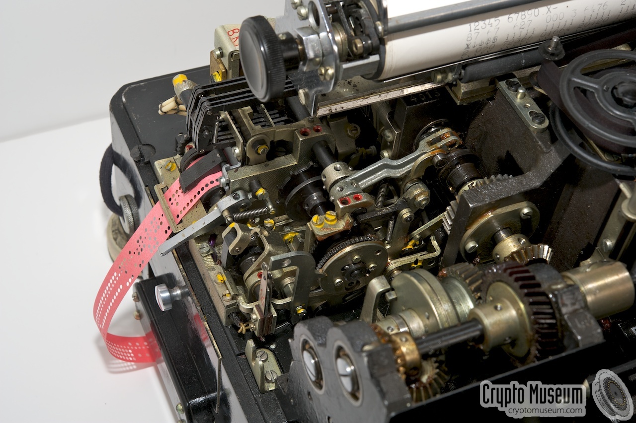
The image on the right shows a typical M-130 cipher machine with its
top lid removed. At the front of the unit, right behind the keyboard,
is the actual cipher unit, which is explained further below.
The remaining part is the bare teletype unit,
which acts as a host to the cipher unit.
The teletype unit is a marvel of mechanical engineering. As it was developed
in the same era as the M-125 (Fialka),
it shares some of its characteristics. The entire unit is driven by a 22V motor mounted
at the rear right, in combination with a complex system
of cog-wheels and axles.
|
|
|
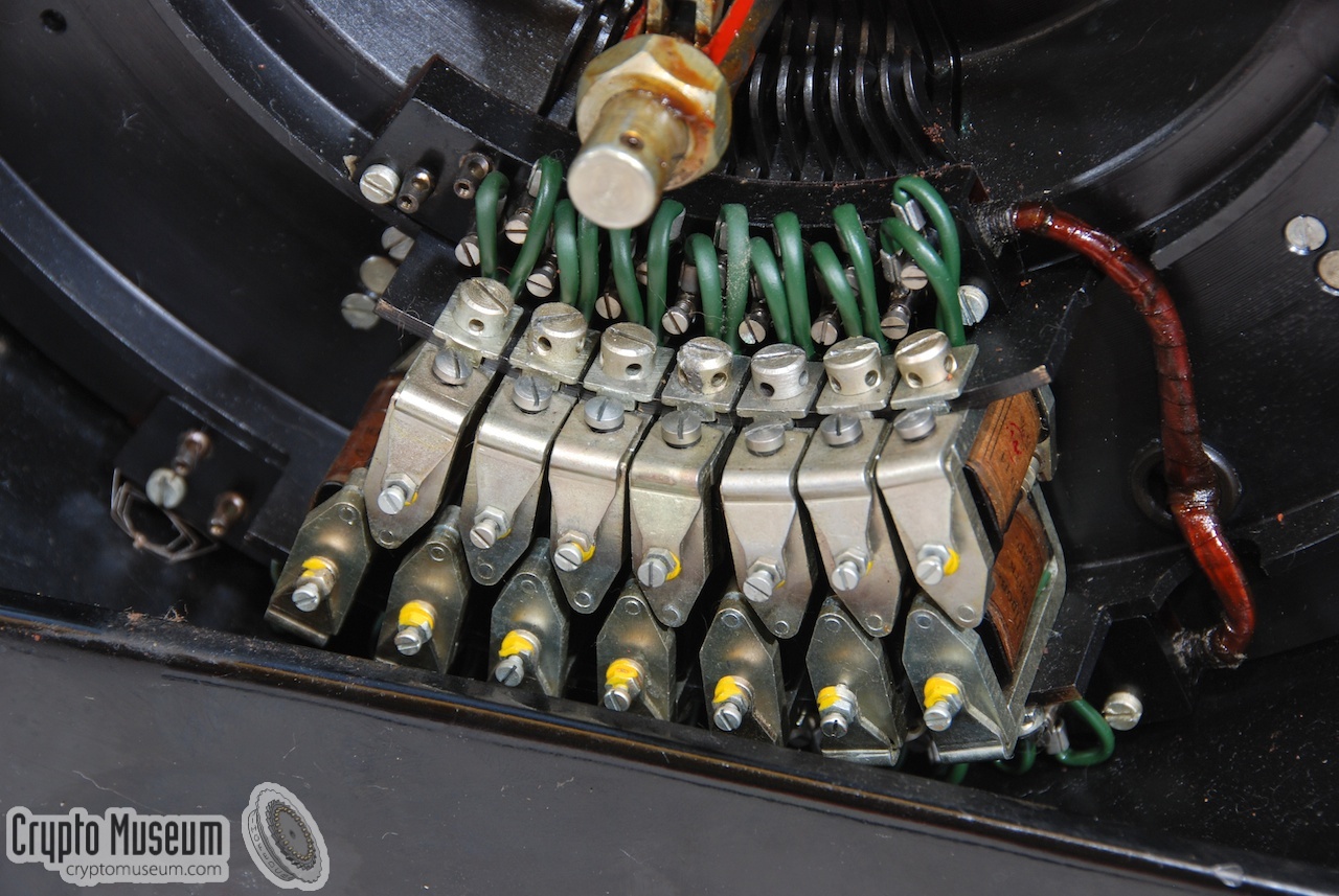
The encrypted or decrypted text is printed on a paper roll by means of a
set of 12 hammers, much like a typewriter.
The hammers are controlled by a set of solenoids
at the rear of the machine. When a solenoid is activated, the corresponding
hammer is released.
At the rear left is a built-in paper puncher
that allows the encrypted output to be stored on a punched paper strip.
The paper for the puncher is taken from a drawer
at the right. A knob at the right
is used to select the output device: printer (К),
puncher (П) or both (ПК).
Note that the puncher can only be used in encryption or plaintext mode.
It is disabled in decryption mode.
At the front left is a paper tape reader,
which can only be used in decryption and plaintext mode.
|
|
The actual cipher unit is located in the front part of the basic teletype machine.
It takes the form of a complete pre-assembled unit, built on a heavy aluminium
base plate, which is mounted in an empty space at the front.
It can be removed by releasing four bolts at the corners of the unit.
|
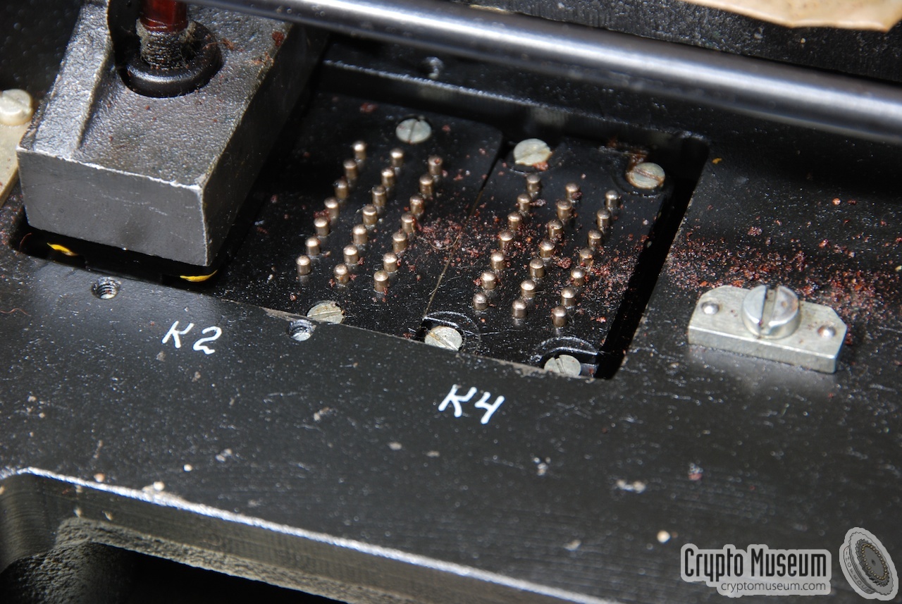
The image on the right shows the bare cipher unit once it is removed from the
machine. It connects with the teletype machine by means of a
contact block at the rear, which mates with a
set of 42 spring-loaded contacts
in the base of the teletype unit.
At the heart of the cipher unit are five electrical cipher rotors, each with 30
contacts at either side. They are described in greater detail below.
Four additional mechanical pin-wheels control the irregular stepping of the
cipher rotors. They are also explained in more detail below.
|
|
|
When the unit is running, the middle rotor (3) always makes a single step on every
key-press. It always moves upwards (i.e. the numbers move up when viewed from
the front). The outer two rotors (1 and 5) also move up, but their stepping may be
inhibited by the presence of a pin on one of the stepping rotors.
The remaining two rotors (2 and 4) move down on a key-press. Their stepping may
also be inhibited by the presence of a pin on the matching stepping rotor.
The cipher rotors are connected to the electric circuit of the cipher unit, by means
of a static entry disc at either side.
At the far left of the cipher unit are two patch panels, with 10 wires each.
A counter,
mounted on top of the unit, is used for counting the number of characters
entered on the keyboard. It can be reset by operating a lever at its right side.
The cipher rotors
can be removed
by releasing both static discs and pushing them sideways (outwards).
|
Device Rotor-based cipher machine Purpose Encryption of numeric weather reports Model M-130 Name KORALL (КОРАЛЛ) Manufacturer NIIA (now: Avtomatica) Country USSR (Russia) Year 1965-1966 Rotors 5 (electric cipher rotors) + 4 stepping rotors Dimensions ? Weight ? Quantity 100 (est.) 2
|
4012 Base Richard Brisson, Canada 4013 Full Private collector UK ← complete and functioning 4024 Base ? 4025 Base Auction Team Breker (November 2023) 4028 Base Crypto Museum, Netherlands 4107 Base Crypto Museum, Netherlands 4120 Base Ebay 4124 Base ?
|
-
Base means the bare teleprinter unit only (without cipher unit).
Full means the complete machine (base + cipher unit).
-
If the serial numbers are contiguous, it is likely that between 150 and 200
units were manufactured. However, it is also possible that the second digit
(0 or 1) denotes the manufacturing year. This was commonly done in the
USSR. In that case, it is more likely that about 100 machines were made.
|
4012 Base, cipher rotor 2,4 4013 Base, cipher unit, cipher rotor 1,2,5 4018 Stepping rotor 3 4024 Base 4025 Base 4028 Base, cipher rotor 2,3,4 4107 Base, cipher rotor 1,5 4108 Cipher rotor 3,3,5 4120 Cipher rotor 1,5 4124 Base, stepping rotor 1 4125 Stepping rotor 2,3,4,5
|
|
|
|
Any links shown in red are currently unavailable.
If you like the information on this website, why not make a donation?
© Crypto Museum. Created: Wednesday 03 August 2011. Last changed: Thursday, 24 July 2025 - 08:18 CET.
|
|

|
|
|
|
| | |


![M-130 cipher machine courtesy Peter Klampferer, Austria [1]](img/301366/138/full.jpg)


![Meteorologic Department bunker. Source: ZFWW website [3]](svg/bunker.svg)


