|
|
|
|
|

|
|
Enigma Family tree → History →
Before going into detail, we have to consider
that there are different models, versions and variants of the Enigma.
Some of the differences make it impossible to decrypt a message
that was encrypted on another model. That does however not affect the working
principle as explained here. Let's first look at the simplified circuit diagram
of a standard 3-wheel Wehrmacht Enigma.
For clarity, only 5 of the 26 contact points of each rotor are shown
in the example below.
|
| |
Simplified circuit diagram of a 3-rotor Service Enigma
|
Letters are 'scrambled' by a set of movable rotors each with 26 contacts
on either side. Each contact on one side is connected (wired) to a
contact on the other side in some random fashion.
Some models, like the standard Service Enigma and the M3 have
3 such movable rotors, but the M4 model, used later in the war
exclusively for the German U-Boats, has 4 rotors.
Each time a key is pressed, the right most rotor is advanced
by one step, resulting in a different mapping of the
internal wires. As a result, each new letter is encoded
differently.
Each rotor has one or more notches that may cause
the next rotor to be moved by one position too. If a rotor has only
one notch, it needs to complete a full revolution before the rotor
to its left is advanced by one position.
The keyboard consists of 26 keys, marked A-Z.
Whenever a key, say Q, is pressed the rotors will
move into a new position and a contact is closed.
As a result a current will flow.
The wires from the 26 keys are connected to a static disc called
the Stator or Entrittswalze (ETW). The order in which
the keys are connected to the 26 contacts on the ETW varies
between the different Enigma models.
Leaving the ETW, the current enters the rightmost rotor (1) via one
of the contacts at its right hand side. The internal wiring of that rotor 'translates' this current to one of the contacts on the left side of
the rotor. From there the current is 'handed over' to the next rotor,
and so on. Left of the rotor stack is the
Reflector, or Umkehrwalze (UKW). This UKW sends the current
back into the rotor stack, but this time the current flows
from left to right, until it reaches the ETW again. From the
ETW the current goes to the lamp board where the corresponding
letter (E in the example) will be lit. It is inherent to this
design, that a letter can never be encoded into itself.
Before starting the ciphering process, the Enigma needs to be
setup in a known way at both sides of the communication link.
This means the rotor order (Walzenlage) needs to be known
as well as the starting position of each rotor (Grundstellung).
In order to further complicate things, each rotor has a settable
index ring that moves the wiring independant of the rotor's alphabet.
This is called the ring setting (Ringstellung).
To make life even more complex, the Wehrmacht machines were all
equipped with a plug board, or patch panel (Steckerbrett),
that allows pairs of letters to be swapped.
Any number of cables from none to 13 may be connected to the
Steckerbrett, meaning that between 0 and 13 letter pairs may
be swapped. If a letter is not mapped (i.e. no stecker is used for
that letter), the letter is said to be Self-Steckered.
See below for more information.
|
|
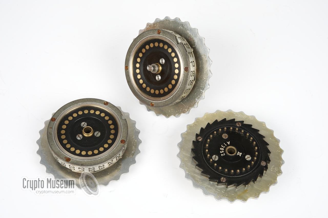
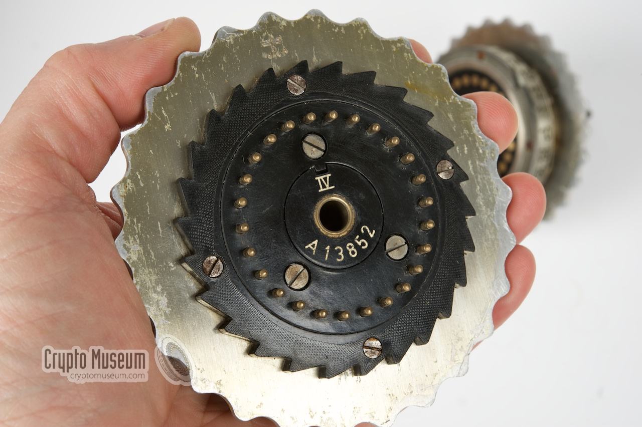
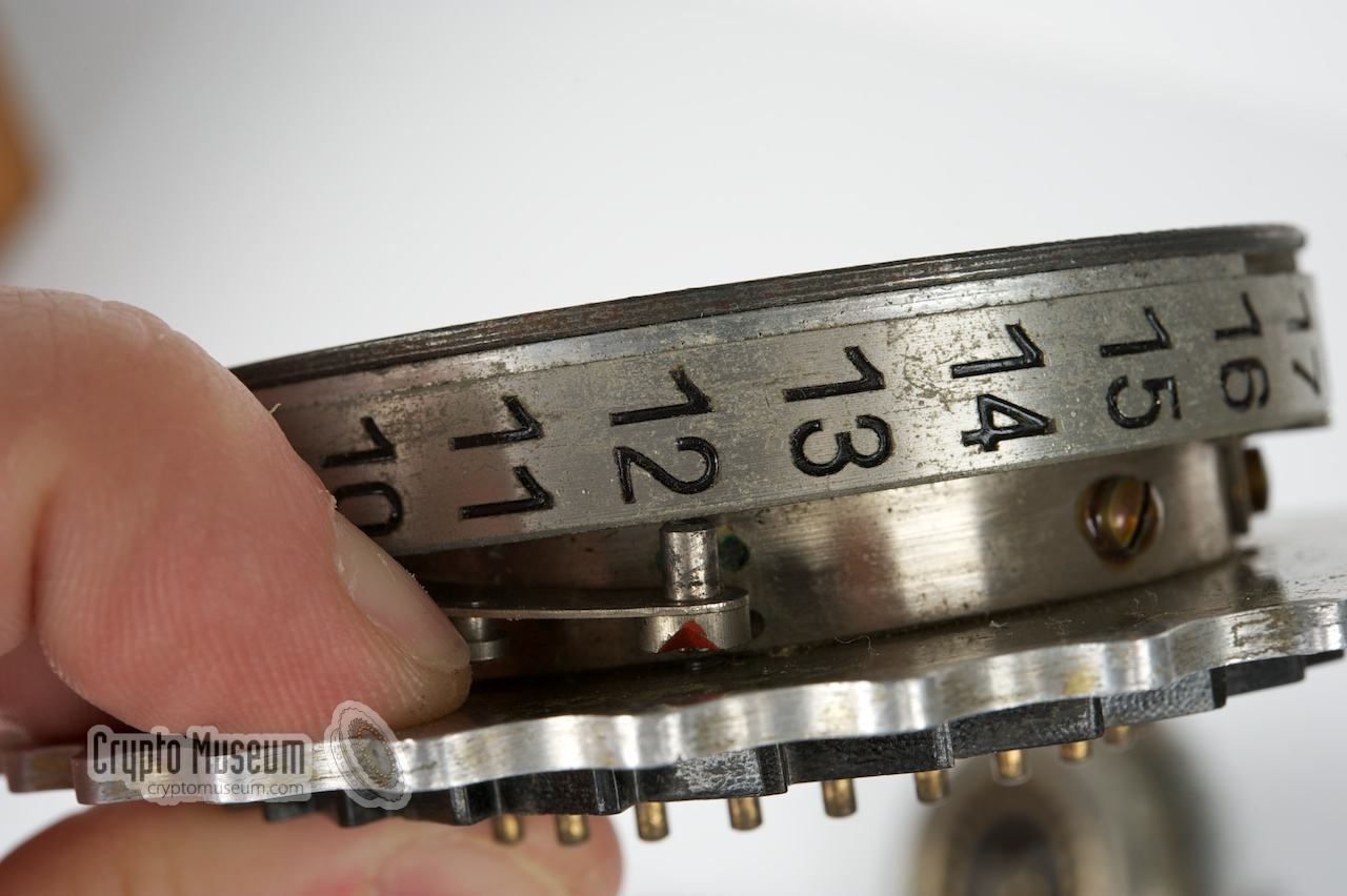
Each rotor has 26 positions, which we call A-Z. The index of a
rotor is engraved (either as A-Z or 01-26) along the side of the rotor.
The current position of each rotor is visible through a small window in
the top lid of the machine.
A rotor has 26 spring-loaded contacts on its right side, and 26 flat-faced
contacts at its left side. Inside the rotor are 26 wires that connect the
spring-loaded contacts at the right, to the flat-faced contacts at the left,
in some scrambled order.
Each rotor is identified by a Roman number
(e.g. I, II, II, IV, V) and has a wiring that is unique for that number.
|
|
The video above illustrates how the rotor scrambles the alphabet.
When pressing a letter on the keyboard, the current from the battery
enters the corresponding contact on the right side of the first rotor.
The wiring inside the rotor 'translates' this to another letter,
after which the current leaves the contact of the output letter
at the left side of the rotor. It then
passes the second and the third rotor, where a similar translation
takes place, until it hits the reflector at the far left.
|
|
Below each key of the keyboard is a two-position switch.
The key has to be fully depressed before the switch is activated.
The key also controls the rotor stepping. Whenever a
key is pressed, the rightmost rotor makes a single step before
the switch is activated and a lamp is turned on.
|
Each rotor has 26 positions that we will call A-Z. The index of each
rotor is engraved (either as 01-26 or A-Z) along the side of the rotor.
The current position of the rotor is visible through a small window in
the top lid of the Enigma.
When a key is pressed, the rightmost rotor is rotated counter clockwise,
when viewed from the ETW. If the letter A
was visible in the window, the letter B will be visible next time
the rotor is moved.
Each rotor has a ring that can be used to rotate
the wiring independantly of the index. This can be regarded as
creating an offset in the opposite direction.
The rotor-turnover notches are fixed to the index ring.
Therefore the turnover of the rotor to its left
will always happen at the same letter in the window,
but the wiring will be different (i.e. rotated).
|
|
Rotor movement is much like the odometer in a car. If the rightmost
rotor has made a full revolution, it will carry on the next rotor
by one step. Most Enigma models are equipped with stepping levers
and notches, rather than with cogwheels.
Whenever the position of a notch is reached, it engages a pawl.
On the next key press, this pawl will carry-on the adjacent rotor.
This principle is called Enigma stepping and has the strange
side-effect that the middle rotor steps twice
(on two successive key presses)
if the leftmost rotor also makes a step. This phenomena,
known as the double stepping anomaly (see below),
has been described in detail by David Hamer in 1997 [1].
|
|
|
Double stepping of the middle rotor
|
|
|
|
The table below should illustrate what happens.
Rotor I is placed in the rightmost position (also called the 'fast'
position). It causes the rotor to its left to step when it changes from
Q to R. Rotor II is in the middle position. It causes a step
when changing from E to F. Here is what happens:
|
| III | II | I | <-- wheel order |
|
|
| A | D | O |
| A | D | P |
| A | D | Q |
| A | E | R | <-- 1st step of middle wheel |
| B | F | S | <-- 2nd step of middle wheel |
| B | F | T |
| B | F | U |
|
When the fast rotor changes from Q to R, it causes the middle rotor (II)
to step from D to E. One the next step, the rightmost rotor changes from
R to S and the middle rotor makes one more step: from E to F.
At the same time, the middle rotor causes the left rotor (I) to make
a single step. This double stepping anomaly reduces the cryptographic
period of the system somewhat. Instead of 26 × 26 × 26 (= 17,576),
the period has been reduced by 25 × 26 (= 650), resulting in 16,926.
Some Enigma machines, such as the Zählwerksmaschine A28
and the Enigma G, were driven by a gear mechanism with
cogwheels rather than by pawls and rachets.
These machines do not suffer from the double stepping
anomaly and behave exactly like the odometer of a car.
They have the additional advantage that, in case of a typo,
they can be wound back by means of a crank, whereas machines with Enigma
Stepping can only be advanced (i.e. moved forward).
|
|
Inside the UKW (Umkehrwalze, reflector) are 13 wires that connect the
26 letters in pairs. The UKW basically translates a letter into another
letter. Once the current from the ETW (Eintrittswalze, entry disc) has
passed all three rotors, it ends up at one of the contacts of the UKW.
The UKW then passes the current to another contact, and sends it back
through the rotor stack.
|
The video above illustrates how the current flows through the leftmost
rotor and then trough the UKW and back through the leftmost rotor.
The UKW is repsonsible for the fact that the machine is reciprocal
(reversible), which means that the encryption and decryption processes
are identical. It is also responsible for one of the weaknesses of the
Enigma: as the UKW always sends the current back through a different
path, a letter can be encoded into any other letter but never into itself.
|
The Wehrmacht variants of the Enigma (Service Enigma, M3 and M4) were
equipped with a plug board (Steckerbrett) at the front, that would
allow any pair of letters to be swapped.
For this purpose 12 patch cables
were usually supplied: 10 to be used on the Steckerbrett and 2 spares
that were stored inside the top lid of the case.
As the Steckerbrett is connected between the keyboard and the ETW,
each encoded letter will go through the stecker mappings twice.
This does not affect the machine's reciprocity (reversibility)
and a letter can still not be encoded into itself.
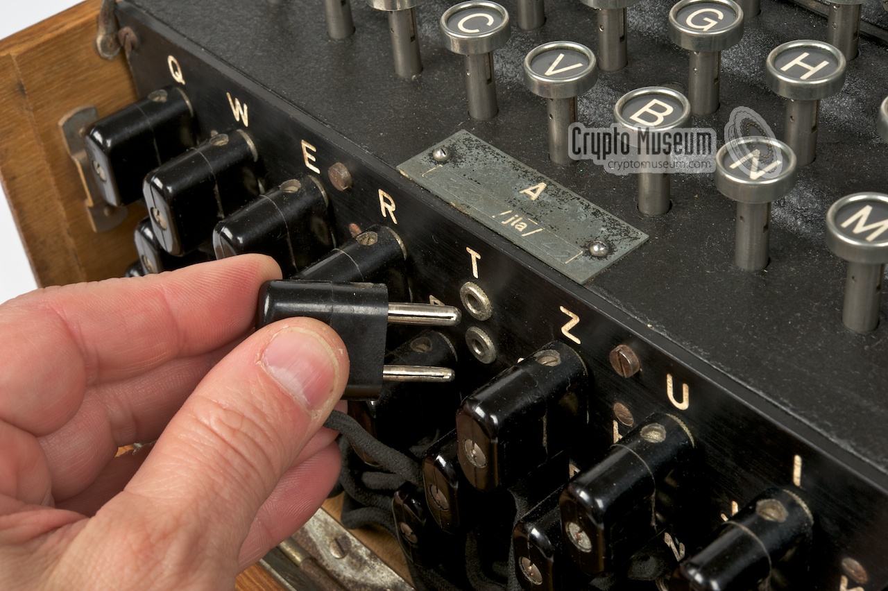
Each patch cable as a 2-pin plug at either side.
Each plug has a thick and a thin pin,
so that it can not be inserted
the wrong way around. The cable swaps the wiring between
the plugs. In other words: the thick pin of one plug is connected to the
thin pin of the other one and vice versa.
|
The image on the right shows a double-ended plug with a thick and a thin pin.
Swapping the letters in pairs means that if A is transposed into Z, the
reverse is also true: Z is transposed into A. This is called
self-reciprocity.
Compared to a single-ended Steckerbrett,
this reduces the total number of possible combinations significantly.
The same self-reciprocity was exploited by Gordon Welchman
when improving Turing's Bombe,
resulting in shorter Bombe-runs when breaking the Enigma's daily keys.
It effectively eliminated the Steckerbrett from the equasion.
|
|
|
With 26 letters, and hence 26 sockets on the Steckerbrett, a maximum of 13
patch cables could be installed. Any number of cables between 0 and 13 was
possible and the maximum number of combinations would be reached when the
number of patch cables was different each day. In practice however, the
German operation procedure generally instructed the use of 10 cables.
The total number of combinations for each number of cables is calculated
as follows [2]:
The table below shows the number of combinations for each number of cables:
|
| Cables (n) | Possible combinations (N) |
|
|
| 0 | 1 |
| 1 | 325 |
| 2 | 44,850 |
| 3 | 3,453,450 |
| 4 | 164,038,875 |
| 5 | 5,019,589,575 |
| 6 | 100,391,791,500 |
| 7 | 1,305,093,289,500 |
| 8 | 10,767,019,638,375 |
| 9 | 53,835,098,191,875 |
| 10 | 150,738,274,937,250 | <-- Most common number of cables |
| 11 | 205,552,193,096,250 | <-- Highest number of combinations |
| 12 | 102,776,096,548,125 |
| 13 | 7,905,853,580,625 |
|
|
| Total | 532,985,208,200,576 |
|
The table above shows that it is theoretically possible to
multiply the number of possibilities of a non-Steckered machine
(approx. 713 million) with over 500 million million Stecker
combinations. However, as the Germans always used a fixed number of
cables — first 6, later increased to 10 —
the multiplication factor was 'just' 150 million million.
Also note that the mathematical optimum is at 11 cables, not at 10.
With more than 11 cables, the number of possibilities decreases again.
It might have been better though not
to restrict the number of cables at all and use all possible combinations.
Also note that the number of possible combinations with a double-ended
plugboard is significantly less than with a single-ended one.
➤ History of the Steckerbrett
|
|
The total number of possible settings of the Enigma machine can be
calculated in various ways. A detailed description of the mathematics
behind the Enigma can be found in The Cryptographic Mathematics
of Enigma, distributed by the NSA in 1996 and last updated in 2016 [3].
In this publication, it is assumed that the rotor wiring is unknown,
resulting in astronomical figures.
|
|
According to Kerckhoffs' Principle however, we should assume that a
possible attacker has full knowledge of the system, including its wiring [5].
So, in order to make a more realistic estimation of the number of possible
settings, we assume that the attacker knows the wiring of the rotors, the
entry disc (ETW) and the reflector (UKW). We therefore only need to
consider the possible settings of the rotors and the configuration of the
Steckerbrett. Let's first look at the rotors:
|
| English | German | Calculation | Total | |
|
|
| Rotor order | Walzenlage | 5 x 4 x 3 | 60 | |
| Ring setting | Ringstellung | 26 x 26 | 676 | × |
| Start position | Grundstelling | 26 x 26 x 26 | 17,576 | × |
|
|
| | | Total | 712,882,560 | |
|
Please note that the Ringstellung of the leftmost rotor has no effect
as its notch can not move the rotor to its left.
Next we take the Steckerbrett into account, and we assume
that the Germans always used exactly 10 cables on the Steckerbrett.
This leads to the multiplication:
                    712,882,560
            150,738,274,937,250 ×
107,458,687,327,250,619,360,000 ≈ 1.07 x 10²³ ≈ 276 = 76 bits
|
|
Compared to modern computer encryption, this would be the equivalent of 76 bits;
which is quite an achievement for its era. If we consider the
4-rotor Naval Enigma (M4), we must take into account that the
M4 has an extra rotor to the left of the three standard rotors.
This 4th rotor cannot be exchanged with the other rotors and does not
move during encypherment. The remaining 3 rotors are chosen from a
set of 8.
This leads to the following calculation:
|
| English | German | Calculation | Total | |
|
|
| Rotor order | Walzenlage | 8 x 7 x 6 | 336 | |
| Reflector | UKW | β or γ | 2 | × |
| Extra rotor | Zusatzwalze | b or c | 2 | × |
| Ring setting | Ringstellung | 26 x 26 | 676 | × |
| Start position | Grundstelling | 26 x 26 x 26 x 26 | 456,976 | × |
|
|
| | | Total | 415,182,802,944 | |
|
If we multiply this with the number of Steckerbrett settings,
we get the following:
                   415,182,802,944
               150,738,274,937,250 ×
62,583,939,499,390,760,715,264,000 ≈ 6.26 x 1025 ≈ 286 = 86 bits
|
|
From the above it is clear that Enigma M4 was significantly better
than a 3-rotor Enigma I, as it offers almost 600 times the
number of possible settings of the Enigma I. In practice however,
some settings were redundant, and not all factors (rotor order, start position,
ring setting and plugboard) contributed equally to the strength of the cipher.
This will be discussed below.
|
Key space is not the same as the possible number of settings
discussed above. There were various mechanical and procedural restrictions
that reduced the useful or effective key space, most of which
are listed further down this page. Here are some considerations:
Under certain circumstances, the middle rotor
will make two steps on two successive key presses. This property — known
as the double-stepping anomaly — is inherent to the rotor stepping mechanism,
and was described by David Hamer in 1997 [1]. This means that one of the
settings of the middle rotor is redundant. As a result, the total number
of start positions of a 3-rotor machine (26 × 26 × 26 = 17,576)
has to be reduced by 650 (25 × 26) resulting in 16,926.
|
| English | German | Calculation | Total | |
|
|
| Rotor order | Walzenlage | 5 x 4 x 3 | 60 | |
| Ring setting | Ringstellung | 26 x 26 | 676 | × |
| Start position | Grundstelling | 17576 - 650 | 16,926 | × |
|
|
| | | Total | 685,518,560 | |
|
The above table shows the effect of the double-stepping anomaly.
The total key space of a 3-rotor Enigma I, with 5 rotors and
10 cables on the Steckerbrett, is now calculated as follows:
685,518,560 × 150,738,274,937,250 = 103,333,885,171,867,710,360,000
In the same vein, the key space of a 4-rotor naval Enigma M4, with 8 rotors
and 10 cables on the Steckerbrett, can be calculated as:
414,592,249,344 × 150,738,274,937,250 = 62,494,920,468,468,777,953,664,000
The key space was further reduced by limitations in the operating procedures,
such as the non-clashing rule, the non-repeating rule, the Clarkian rule and,
in the case of naval Enigma, the mandatory use of one of the special naval
rotors (VI, VII and VIII).
A more complete overview of the weaknesses
that caused a reduction of the key space is given below.
|
Please note that cipher strength is not the same as key space.
The strength of the cipher is determined by many factors, of which the key space
is just one. The effect of the Ringstellung (ring setting) on the strength
of the cipher is marginal, as it only affects the turnover position of the
adjacent rotor. Furthermore, the Steckerbrett is static,
which means that its configuration does not change during encipherment.
Despite its huge number of possible settings, it is little more than a static
monoalphabetic substitution cipher, which is relatively easy to break.
For the WWII codebreakers of Bletchley Park (BP) the number of
cables on the Steckerbrett did not play a significant role
when using the Turing-Welchman Bombe to determine the
order of the rotors and their initial setting.
Furthermore, the double ended nature of the
Steckerbrett — letters were always swapped in pairs — was
used by Welchman to improve the effeciency of the Bombe.
The above limitations, together with other design flaws of the Enigma, are
discussed in detail in a paper by Olaf Ostwald of 2023 [6].
|
|
|
Differences in Enigma models
|
|
|
|
When examining the different versions of the Enigma,
the following differences can be observed:
|
- Steckerbrett
Some models have a Steckerbrett (plug board, or patch panel) and some don't.
Only the military machines, used by the German Army, Air Force and Navy,
had such a plug board.
The maximum number of patch cables is 13 (as we have 26 letters),
but the number of cables supplied with the unit varies. The
highest number of permutations is achieved with 11 patch cables.
In most cases, 10 cables were used on the plug board, with two spares
stowed in the case lid.
The Steckerbrett was used exclusively by the German Wehrmacht and did
not appear on any other model.
➤ History of the plug board
- ETW mapping
The Eintrittswalze (ETW) can be mapped in the order of the alphabet:
ABCDEFGH... etc, but also
in the order of the keyboard: QWERTZUIO...
On the Japanese Enigma T (Tirpitz), the contacts of the ETW
are organised in a random order: KZROUQHY...
- Numbers or letters
Some rotors have numbers engraved on their circumference (01-26),
whilst others have letters (A-Z).
Initially all Enigma machines had letters on their rotors.
This is definitely the case for all commercial Enigma
machines produced prior to WWII. When the German Army adopted the machine
for military use, they added a Steckerbrett
(see above) and and decided to have numbers on the rotors (01-26).
Naval machines however, (M1, M2, M3 and M4), remained to have letters.
- Number of differently wired rotors
Most models have three cipher rotors, but the M4 has four
of them.
Also some models have a larger range of rotors (e.g. 8) to choose from.
The rotors may be placed in the machine in any desired order.
- Extra rotor
On the Naval M4 (a 4-rotor machine), the extra rotor is not moved
automatically, but can be set manually to an initial position.
Furthermore the extra rotor cannot be exchanged with the other
three rotors as it has spring-loaded contacts at both sides.
The 4th rotor was supplied as a pair with a thinner version of the UKW.
For UKWs B and C, the extra rotors Beta (β) and Gamma (γ)
where supplied,
hence the name Griechenwalze (Greek rotor).
They may be used however in any combination.
- Settable UKW
The military models have a fixed UKW, but the early commercial models
have an UKW protrudes the top lid of the machine, and can be set to any of
26 positions at the start of a message.
This is sometime erroneously referred to as a 4-rotor machine, but in
reality it is a 3-rotor machine with a settable UKW. The UKW is not
driven by the other rotors.
- Driven UKW
Some models, such as the Enigma G31 (Abwehr Enigma)
and the Zählwerk Enigma A28,
have an UKW that protrudes the top lid. In these machines, the UKW
is driven by the other rotors. Due to mechanical differences in the rotor
stepping mechanism — cogwheels instead of pawls and rachets — these machines
do not suffer from the double stepping anomaly discussed below.
Furthermore, the stepping
mechanism can be wound back and forth by means of a crank, allowing for
correction of mistakes more easily.
- Rotor wiring
Although the wiring of the rotor I to V was identical for all military
Enigma machines during WWII, other versions used a different wiring.
This wiring could be different for each customer.
➤ Different rotor wirings
- Rotor stepping
Two different rotor stepping mechanisms are known:
a simple one – known as Enigma Stepping – in which
pawls and levers are used to advance the rotors, and a more advanced one,
in which cog wheels are used to drive the rotors. Only machines in the
Zählwerk class
(A28,
G31)
fall into the latter category. All other machines had
the simpler (and cheaper) Enigma Stepping, which suffers from the
double stepping anomaly (see below).
- Double stepping anomaly
As a result of the mechanical principle of the Enigma Stepping mechanism,
the middle rotor 'suffers' from a so-called double stepping anomaly,
described in detail in a paper by David Hamer in 1997 [1].
Enigma machines of the Zählwerk class,
such as the Enigma-G, do not suffer from this anomaly,
as their cipher rotors are driven by cog wheels.
➤ More about the double stepping anomaly
- Number of notches on each rotor
In the basic design, each rotor has one notch which, after a full revolution
of the rotor, causes the rotor to its left to advance by one position.
This causes a regular stepping of the rotors, similar to the odometer in a
car.
Some versions have two or even more notches on each rotor, causing more frequent changeovers of the next rotor.
The three rotors of Enigma G31
and Zählwerk Enigma A28
have 11, 15 and 17 notches respectively.
This causes irregular rotor stepping, which is much more difficult to predict.
➤ More about notches on the rotors
- Manufacturer
Initially there was only one Enigma manufacturer, but during WWII
they were built by various factories throughout Germany.
Although these machines were functionally identical, there are a few
cosmetic differences.
In addition there are physical differences between the thin
rotors of the Enigma M4 from some manufacturers.
➤ Enigma manufacturers
|
|
The basic Enigma design has a number of weaknesses that were
exploited by the Allied codebreakers of
Bletchley Park During WWII.
Here are some examples:
|
- A letter can never be encoded into itself
One of the key properties of the Enigma design is the fact that
a letter can never be encoded into itself. In other words: when
the letter A is pressed, every lamp on the lamp panel can be
lit, except for the letter A itself.
This property is caused by the fact that a reflector (UKW) is used;
the return path is always different from the entry path.
- Regular stepping of the rotors
In most Enigma machines, the rightmost rotor makes a
full revolution before the rotor to its left advances by one
position, in the same way as an odometer.
As a result, the 2nd rotor only steps once every
26 characters and the 3rd rotor hardly ever moves. This makes
the machine more predictable.
Some variants, such as Enigma T,
Enigma A28
and Enigma G, had rotors with multiple turnover notches to cause irregular stepping.
- Double stepping of the middle rotor
Under certain circumstances, the middle rotor can make two steps on two
subsequent key presses. As this reduces the number of effective settings
of that rotor from 26 to 25, it slightly reduces the machine's cipher
period and (by the same amount) its key space. The double stepping feature
was described in 1997 in a paper by David Hamer [1].
- 4th rotor not moving
In Naval Enigma M4, the extra rotor (Zusatswalze) at the far left
can be set to any of 26 positions at the start of a message. During
encipherment however, the Zusatzwalze never moves.
The combination of Zusatzwalze and the thin reflector (UKW)
can be regarded as a selection between 26 different UKWs.
- 2 Notches on the extra Naval rotors
To ensure a more frequent stepping of the rotors, the three extra Naval rotors
(VI, VII and VIII) each have two notches. However, as 2 shares a common
factor with 26 (26 can be divided by 2) the cipher period is effectively
halved. It would have been better to use 3 or more notches, like on
Enigma T where each rotor has 5 notches.
- Mandatory use of extra Naval rotor
If, on any given day, a naval operator could pick any three rotors from the
available 8, there would have been 8 × 7 × 6 = 336 possible different
rotor orders. In practice however, the Navy used at least one
of the extra Naval rotors each day (VI, VII or VIII),
which reduces the number of possible rotor orders and therefore also
the key space.
- Mandatory key rules
There were several other rules that were intended to improve cipher security,
but that in reality reduced the key space significantly. One example is the
so-called non-clashing rule that dictated that a particular rotor
could not be used in the same position on two consecutive days.
There was also the non-repeating rule that said that the same rotor order
could not be used twice within one month.
In addition, the Red and Light Blue keys used the
Clarkian rule — named after its discoverer L.E. Clarke — as a result of
which a rotor could not be followed by a consecutive rotor.
- Letters always swapped in pairs on the Steckerbrett
Each patch cable on the Steckerbrett swaps a pair of letters.
Compared to a
single-ended Steckerbrett, this reduces the number of
possible combinations dramatically. Furthermore, swapping letters
in pairs, makes the Steckerbrett self-reciprocal, as a result of
which it can be eleminated from the equasion when determining the
rotor order for a given day.
Although a
single-ended plugboard — which does not suffer from
these restrictions —
was tried in 1927, it was thought to be too prone to mistakes.
➤ More
- Fixed number of cables on the Steckerbrett
The Steckerbrett has 26 sockets, one for each letter of the
alphabet. Cables were used to swap pairs of letters. If
a cable was omitted, that letter would not be swapped.
In theory, any number of cables between 0 and 13 would thus
be possible, with 11 cables producing the highest result.
In practice, the procedures commanded the use a fixed number of
cables (10 in most cases), which greatly reduces the
maximum number of possibilities.
➤ More about the Steckerbrett
|
A great animation on how the Enigma works is available below.
It was created in December 2021 by Jared Owen, and features
Enigma I —
the most common Enigma model that was used by the German Army during
WWII. For more great
animations, visit Jared Owen's YouTube channel [4].
|
During WWII, the British counterpart of Enigma was
Typex, also known as Type-X.
Developed in 1934 it was almost an exact copy of the German Enigma,
albeit with some additions, such as a motor-drive and two printers: one at
either side.
Typex has 5 rotors, of which only 3 were moving during
encipherment. During WWII some Typex machines were configured
in such a way that they could be used a Enigma machines. They were used for
decrypting Enigma messages once the daily key had been broken.
➤ More information
|
|
|
During WWII, SIGABA was the US' answer to Enigma.
Developed in the late 1930s as a joint effort of the US Army and US Navy,
it was used for high-level traffic. The machine had 15 cipher rotors – 10 large
ones and 5 smnaller ones – and was more complex than Enigma or Typex.
For allied communication during WWII, the machine was downgraded to the
so-called Combined Cipher Machine (CCM), so that it became
compatible with it British counterpart: Typex CCM.
In 1952, it was replaced by KL-7.
➤ More information
|
|
|
During WWII, the Swiss Army and diplomatic services used a
modified version of the German Enigma K — the commercial Enigma that had been
freely available on the open market prior to the war — known as the
Swiss Enigma K.
After the Swiss found out that the Germans were able to read their diplomatic
traffic, they developed their own variant which they named NeMa,
or Neue Maschine (new machine).
Although the machine was developed between 1941 and 1943, it was not taken
into production until 1946, as a result of which it came too late to be of any
importance during the war.
➤ More information
|
|
|
Another rotor machine that bares properties of the Enigma, is the
American KL-7. Introduced in 1952 as AFSAM 7,
the machine was used by the American Armed Forces and by NATO.
It has 8 cipher rotors, of which 7 are moving during encipherment.
Unlike Enigma, this machine does not have a reflector (UKW).
Furthermore, each rotor has 36 contact points at either side, 10 of which are
looped back to the input of the drum.
It was the first machine to use this so-called re-entry feature.
➤ More information
|
|
|
Interestingly, most of the
exploitable Enigma weaknesses listed above, were
fixed in the Russian M-125 cipher machine,
also known as FIALKA,
that was introduced in 1956. It has 10 cipher rotors, all of which
feature irregular stepping. Furthermore, adjacent rotors move in
opposite directions.
The Steckerbrett is replaced by a punched card that allows
all possible permutations. It avoids operator mistakes and
is installed in seconds.
And although the operating principle of Fialka
is almost identical to that of the Enigma, on Fialka a letter can
be encoded into itself.
This clearly shows that the Russians had a good understanding of
Enigma's operating principle, but it also suggests that they knew
exactly how its weaknesses had been exploited by the Allied codebreakers
during World War II.
➤ More information
|
|
|
- David Hamer: Actions involved in the 'double stepping' of the middle rotor 1
Cryptologia, January 1997, Volume XX, Number 1.
- Arthur Bauer, Funkpeilung als alliierte Waffe gegen Deutsche U-Boote 1939-1945.
ISBN 3-00-002142-6. The Netherlands, 1997. German. p. 33.
- Dr. A. Ray Miller, The Cryptographic Mathematics of Enigma
NSA. Center for Cryptologic History. USA. 1996. 3rd edition 2002.
Revised version 2019.
- Jared Owen Animations, How did the Enigma Machine work?
YouTube channel Jared Owen, 11 December 2021
- Wikipedia, Kerckhoffs's principle
Visited 10 May 2023.
- Olaf Ostwald, Cryptographic design flaws of early Enigma
5 April 2023.
- Ruben Veenstra, Blender animation of a naval rotor and reflector B
Crypto Museum, 11-16 April 2024.
|
Reproduced here by kind permission from the author.
|
|
|
|
Any links shown in red are currently unavailable.
If you like the information on this website, why not make a donation?
© Crypto Museum. Created: Tuesday 11 August 2009. Last changed: Wednesday, 27 November 2024 - 08:33 CET.
|
 |

|
|
|
|
|
| | |