|
Enigma ← M4 ← M3 ← Enigma I
History of the Enigma plugboard
Enigma I,
Enigma M1, M2, M3
and Enigma M4,
are the only models 1 that have
a Steckerbrett (plugboard) at the front. The Steckerbrett has 26 sockets
that are marked with the letters of the alphabet (A-Z), the numbers 1-26 or
both. Each socket accepts a plug with two pins: a thick one and a thin one. 2
The 2-wire cable between two plugs is cross-wired, as a result of which
letters are always swapped in pairs. Although this introduces a weakness,
it was done for good reasons.
|
The Steckerbrett was manufactured exclusively for the German Armed Forces and
was patented by the Reichswehr (later: Wehrmacht), which is why it was not
available to other customers.
The Steckerbrett as we know it however,
was not the first and only design that was tried.
Various designs were tried before the Reichswehr chose the double-ended
variant that was used during WWII.
Note that this version is not
compatible with any of the earlier designs.
The image on the right shows the Steckerbrett of
Enigma I,
which is nearly identical to that of the Naval machine.
|
|
|
|
This page provides some information about the development of the Steckerbrett,
and provides 'educated guesses' of what the earlier designs may have looked
like. We are indebted to historian Frode Weierud for providing the
historical documents that have made this page possible [1].
|
-
There was a design variant of the Enigma G31 with
a Steckerbrett, but it is likely that it was never taken into production.
In any case, that Steckerbrett was different from the one
described here.
-
Note that the pins of the plugs of the Naval Enigma
(M1, M2, M3 and M4)
are longer than those of the Service Enigma (Enigma I), and are therefore
not interchangeable.
|
|
It has been known for some time, that the initial version of the Steckerbrett
(plugboard) of the military Enigma machine, was very different from the later
double-ended design that was used throughout WWII [2]. It is likely that
single-ended patch cables were used in the initial design.
|
The exact layout remained a mystery however, mainly because documents describing
the early design had not been recovered and no surviving machines with
the early design have been found.
In October 2009, whilst restoring Enigma A604, researcher Tom Perera
noticed that the casting of the bottom plate and the keyboard panel
had circular cut-outs, that apparently had been used at some point [3].
They are normally invisible, as they are hidden behind the Steckerbrett.
After checking Enigma A598,
Crypto Museum was able to confirm that it has the same circular cut-outs.
|
|
|
The image above shows the front side of Enigma A598, after the
plugboard has been removed.
The cut-outs are clearly visible here.
When extended to a full circle, each cut-out has a
diameter of exactly 8 cm, and was clearly designed to accomodate a
circular device. It has been speculated that perhaps it was meant for
two permutation switches, or a storage space for two spare wheels.
However, after carefully studying the possibilities and the available
documentation [4] — quoted in 2016 by Olaf Ostwald and Frode Weierud
in a Cryptologia article about UKW-D — it became clear that
the cut-outs
were most likely intended for the initial design of a single-ended
Steckerbrett that held 26 sockets, arranged in two circles of 13 sockets
each. It is likely that standard 4 mm banana-sockets and banana-plugs
were used, and that the Steckerbrett looked like this:
In this design, 26 patch cables are present: 13 at the left
and 13 at the right. One end of each patch cable is fixed inside the machine,
whilst the other end has a 4 mm banana-plug. The sockets on the left
are marked with the numbers 1-13, and the ones on the right carry the
numbers 14-26, engraved on the panel. The banana-plugs are marked with the letters
of the alphabet: A - M on the left, and N - Z on the right, all engraved
in the isolating grip of the plug. The patch cables were short,
so that each plug could only be fitted in a socket of its own circle.
The image above gives an impression of what it might have looked like,
when the plugboard was configured with the unity matrix (A-1, B-2, C-3, ...
etc.).
Although this design offers a nice and clean solution, it clearly limits the
maximum number of permutations, as each plug is restricted to its own half.
This is confirmed by a document that was discovered by Frode Weierud [4],
in which the number of possible permutations is defined as
13 factorial multiplied by 13 factorial:
13! × 13! = 6,227,020,800 × 6,227,020,800 =
38,775,788,043,630,640,000
|
400 machines with the Mark 1 Steckerbrett (serial numbers A366-A765) [10]
had already been supplied, when the Reichswehr disapproved the design}.
It was probably seen as a weakness that the cables of the left circle
could not be patched to the sockets of the right circle. In an attempt
to improve the design, the manufacturer — Chiffriermaschinen AG —
converted the Steckerbrett of Enigma A366 in such a way that the maximum
number of permutations was obtained. It is likely that the improved design
(which we've named Mark 2) looked somewhat like this:
With this version, the Steckerbrett has 52 sockets, organised as
4 rows of 13 sockets each. The upper two rows are marked with the numbers
1-13 and 14-26. The lower two rows are marked with the letters of the
alphabet: A-M and N-Z. The machine came with 26 patch cables that each
had a banana-plug at either end, and that were long enough to reach the
sockets furthest away (e.g. N to 13). The plugs were no longer engraved
with the letters of the Latin alphabet [4].
It is mandatory that all cables are installed on the Steckerbrett, and
that connections are only made between the upper two and the
lower two rows, which is prone to mistakes.
In practice this must have been a nightmare.
From a cryptographic point of view however, this is by far the best solution,
as it provides the maximum number of combinations, which is calculated
as follows:
26! =
403,291,461,126,605,635,584,000,000
On 14 February 1928, the modified Enigma with serial number A366
was demonstrated in Berlin at the cipher bureau (Chiffrierstelle) of the
Reichswehr. 1
Although Councilor Fenner was able to populate the Steckerbrett according
to a table in less then three minutes, the participants 2 concluded
that 26 long cables and 52 plugs on the plugboard made it
far too complicated.
|
In particular the fact that sockets from the upper two rows must only be patched
to sockets on the lower two rows — i.e. letters had to be patched to numbers —
was seen as a potential cause of mistakes.
Furthermore, it was deemed necessary to extend the length of the wooden
transport case by 5 or 6 cm, in order to accomodate all the cables.
As a result, the design was rejected [4].
Interestingly, this approach was reused by the Russians shortly after WWII
on their M125 Fialka cipher machine,
where it was implemented as a sliding card
reader at the machine's left side.
|
|
|
|
The card reader is in fact a 30 x 30 matrix of switches 3 that are controlled
by a punched key card that is inserted into the drawer. When the drawer is
closed, the holes in the key card slide 30 movable contacts into position.
Like Enigma's Steckerbrett, the card reader is connected between keyboard
and entry disc. But unlike on Enigma, the card is installed in seconds
without mistakes.
|
 |
-
Chiffrierstelle, abbreviated Chi-Stelle,
was the cipher bureau of the German Army — the Reichswehr.
On 16 March 1935, the Reichswehr became the Wehrmacht.
On 4 February 1938, the Oberkommando der Wehrmacht (OKW)
— the German High Command — was formed, after which the Chi-Stelle
became OKW/Chi.
-
Present at the meetings of 14 and 17 February 1928 at the
Reichswehrministerium (Ministry of Defense) in Berlin, were Oblt. Seiffert,
Regierungsrat Fenner, Major Schröder, Frau Rinke and Herrn Korn.
The latter two represented the manufacturer
Chiffriermaschinen AG.
-
As the Russian (Cyrillic) alphabet has more letters than the Latin one,
Fialka has 30 letters, whereas Enigma has 26. As a result the permutation
matrix has 30! possible combinations, rather than Enigma's 26!.
|
After the Mark 2 design had been rejected, the Reichswehr came up with
a simplified design in which just 26 sockets are used. Each socket has
two contacts, and accepts a custom plug with two pins. The sockets
are self-closing, which means that if no plug is inserted, the two
contacts are automatically shorted by an internal spring-loaded shorting
bar fitted behind the socket.
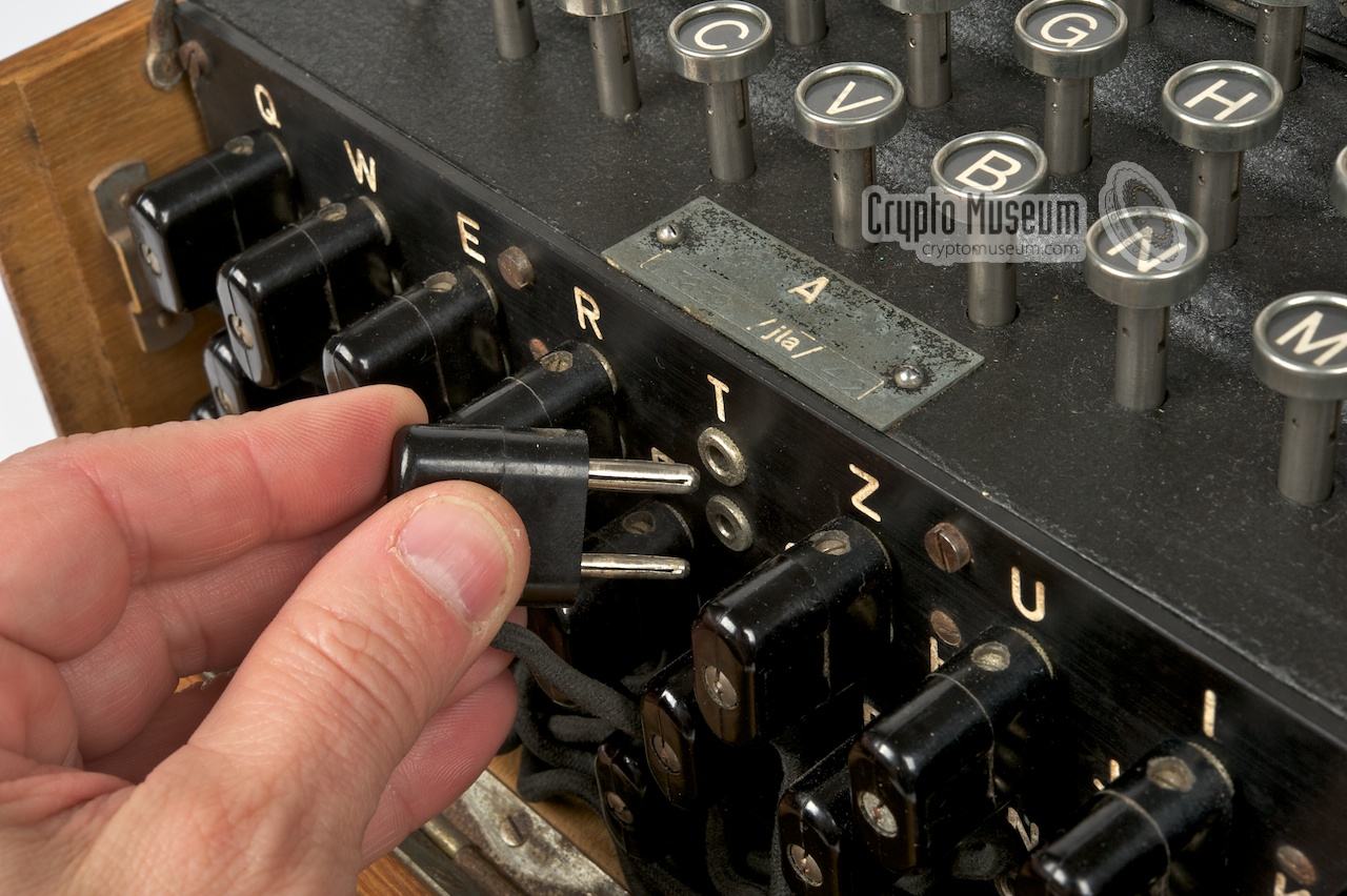
Each machine was supplied with 12 patch cables, each of which had two wires
and was approx. 20 cm long. At either end was a black bakelite plug with two
pins — a thick one (4 mm) and a thin one (3 mm) — that were cross-connected
to the pins of the other plug, as shown here:
Because the two pins have a different diameter, the plug cannot be inserted
the wrong way around.
The diagram below shows a cross-section of the final 1928 Steckerbrett design.
For simplicity, we are only showing the sockets corresponding to the letters
A (01) and Y (25).
The left half of the diagram shows the situation when no plugs are inserted
into the sockets and the shorting bar connects the two contacts of each socket.
The right half shows what happens when both plugs are inserted. The shorting
bar is pushed out of the way, and the plugs take over.
|
Klappe schließen —
Note that for a proper operation of the Steckerbrett, all plugs must be fully
inserted into the sockets, or else the shorting bar may not be pushed out of
the way, leading to internal short-circuits. As a result, more than one lamp
may be lit when a key is pressed. For this reason, the wooden case is
constructed in such a way that the hinged flap at the front can only be
closed when all plugs are fully inserted. This is also the reason why many
machines have the text Klappe schließen (close flap) printed on the inside
of the flap.
All 400 machines, that had already been delivered with a Mark 1
Steckerbrett, were subsequently returned to the factory where they were
reworked into a Mark 3. It is therefore likely that there are no surviving
machines with a Mark 1 Steckerbrett. Sometime later, the
molds were modified as well, so that the casting of later machines
no longer had the circular cut-outs at the front.
The new design accepts any number of cables with a minimum of 0
and a maximum of 13. The designers thought that in practice 6 would be sufficient.
During the war, 10 patch cables were most commonly used on
the Steckerbrett, with 2 spare ones stored in the lid of the wooden case.
With the early machines, the Steckerbrett panel is engraved with both
letters and numbers, which is no longer necessary as there is no difference between upper and lower sockets anymore. This was probably inherited from the
earlier Mark 2 design. It was later dropped in favour of numbers.
|
Although the new Steckerbrett design is much cleaner and
less prone to mistakes, the number of possibilities is far less
astronomical than with the two earlier designs. Because letters are always
swapped in pairs, the Steckerbrett is said to be self-reciprocal. 1
The total number of possible
combinations (N) depends on the number of patch cables (n) and is calculated
with the formula:
If the number of patch cables had been variable (anything from 0 to 13 cables),
the total number of permutations would have been 532,985,208,200,576.
It was decided however, to always have a fixed number of cables on the
Steckerbrett, which reduced the actual number of combinations.
Initially only 6 patch cables were used, which allows the following number
of combinations:
100,391,791,500
From 1 October 1936, 10 patch cables were used, which increases
this number to [10 §2]:
150,738,274,937,250
The table below gives the number of combinations (N) for each number of
patch cables (n) [5][8]:
|
| Cables (n) | Possible combinations (N) |
|
|
| 0 | 1 |
| 1 | 325 |
| 2 | 44,850 |
| 3 | 3,453,450 |
| 4 | 164,038,875 |
| 5 | 5,019,589,575 |
| 6 | 100,391,791,500 | ← Used early in the war |
| 7 | 1,305,093,289,500 |
| 8 | 10,767,019,638,375 |
| 9 | 53,835,098,191,875 |
| 10 | 150,738,274,937,250 | ← Most commonly used |
| 11 | 205,552,193,096,250 | ← Highest number of combinations |
| 12 | 102,776,096,548,125 |
| 13 | 7,905,853,580,625 |
|
|
| Total | 532,985,208,200,576 |
|
|
From the above table it is evident that the maximum number of combinations
is obtained when using 11 patch cables rather than 10. This was known at
Heimsoeth und Rinke (H&R), 2 but 10 cables was considered a practical limit
due to space constraints [7].
|
-
The Steckerbrett is self-reciprocal, which means that if A is patched
to Y, then Y is automatically patched to A. This greatly reduces the
number of combinations, a property that was exploited during WWII
by the codebreakers at Bletchley Park.
Gordon Welchman used it to simplify the operation of the Bombe.
When determining the rotor order for a given day,
the Steckerbrett could be eliminated completely from the equasion.
-
From 1923 to 1935, the name of the company was
Chiffriermaschinen AG (ChiMaAG).
It was succeeded in July 1935 by
Heimsoeth und Rinke (H&R).
|
Update 4 April 2022 —
In an earlier version of this page, the numbers shown in the above table
were slightly different from the ones shown now. They had been obtained
from [5] and were based on approximate calculations. The updated table
has been recalculated by Olaf Ostwald [8] and was verified with various
web-based big number calculators.
Note that the result for 10 cables differs slightly from the calculation
of Willi Korn at H&R [7].
Some of the later production machines were equipped with a cable test facility,
which allowed each wire of a double-ended patch cable to be checked. Machines
with the cable test facility have two additional (single) sockets on the
steckerbrett —
one at either end, marked with a red dot
— and an extra light bulb
at the left end of the lamp panel, that is only visible when the lid is
raised.
The image below shows how a single wire from a patch cable is tested.
Insert the thin pin into the red-marked socket at the left, and the thick pin
into the red-marked socket at the right. If the wire is OK, the extra lamp
at the far left of the lamp panel should light up. Next, turn the cable over,
and repeat it for the other wire.
The extra lamp is usually
marked Kabelprüfung (cable test).
The use of the cable test facility is nicely demonstrated in
this photograph by Ralph Simpson [6].
Note that the extra light bulb will only be visible when the metal lid
over the lamp panel is raised.
|
It should be noted that the plugs of the
Naval Enigma Machines
(M1, M2, M3
and M4) have
pins that are 4 mm longer than
on the Enigma I machines used by Army and Air Force.
The reason for this is currently unknown, but it makes the patch cables
of the two versions incompatible. The difference is illustrated below:
on the Naval Enigma, the pins are 19 mm long instead of 15 mm.
Using Naval patch cables on an Enigma I
is likely to damage the contacts of the Steckerbrett as it pushes the
shorting bar too far inward.
In contrast: the patch cables of Enigma I are too short to disengage
the shorting bar of a Naval Enigma, causing multiple lamps to light up.
For the same reason, the Enigma Uhr
— a Steckerbrett extension that was developed exclusively for
the German Luftwaffe (Air Force) — can not be used with a Naval Enigma,
as the pins will not reach far enough to disengage the shorting bar.
|
- Frode Weierud, Personal communication
October 2017, September 2022.
- Olaf Ostwald & Frode Weierud (2015),
History and Modern Cryptanalysis of Enigma's Pluggable Reflector
Cryptologia, Volume 40, Issue 1, January 2016, pp. 70—91.
➤ Obtained from cryptocellar.org.
- Tom Perera, Personal communication
October 2009 - October 2017.
- Korn & Rinke, Aktennotiz 14.2. und 17.2. 1928
Notes for the record about meetings held on 14 and 17 February 1928.
17 February 1928. Kindly provided by Frode Weierud [1].
- Arthur Bauer, Funkpeilung als alliierte Waffe gegen Deutsche U-Boote 1939-1945.
ISBN: 3-00-002142-6. January 1997. p. 33.
- Ralph Simpson, Personal communication
July 2020.
- Willi Korn, Theoretisches über die Enigma - Glühlampenchiffriermaschine Ch 11 f
Heimsoeth und Rinke, Memorandum. Berlin, 14 October 1938. 1
- Olaf Ostwald, Personal communication
September 2022.
- Olaf Ostwald, Cryptographic design flaws of early Enigma
5 April 2023.
- Astrid Hammarborg, Catalog of Enigma Cipher Machine Wirings
NSA, June 1954.
Obtained via Frode Weierud at CryptoCellar.
|
|
-
Document kindly provided by Frode Weierud, September 2022 [1].
|
|
|
|
Any links shown in red are currently unavailable.
If you like the information on this website, why not make a donation?
© Crypto Museum. Created: Wednesday 11 October 2017. Last changed: Wednesday, 29 July 2026 - 16:27 CET.
|
|

|
|


![Demonstration of a cable check. Photograph by Ralph Simpson [6].](img/EnigmaSB_thumb.jpg "image # EnigmaSB_large.jpg")


![Demonstration of a cable check. Photograph by Ralph Simpson [6].](img/EnigmaSB_large.jpg)


