|
|
|
|
|

|
|
Voice Phone Philips ZODIAC ← Spendex 40
Wideband secure voice terminal · DBT
Spendex-50 is a military secure digital speech and data terminal,
developed in the early 1980s by Philips Usfa in Eindhoven
(Netherlands) for the ZODIAC
tactical digital integrated communications network
of the Dutch Army, where it was known as
Digitaal Beveiligd Telefoontoestel (DBT) 1
or TA-5912.
It is also known by Philips designator UA-8246
and as NSN 5805-17-055-9132.
It features the highly secret
SAVILLE encryption algorithm,
jointly developed by GCHQ
and the NSA.
|
The device is housed in a ruggedized military-grade
die-cast aluminium enclosure. All controls are at the top surface.
It has a 16-button key-pad with an 8-character red LED-display directly
above it. To the right of the display is a
sealed lid below which
the ZEROIZE button is located.
At the top-right are the two contact terminals for connection to a 2-wire
telephone network. At the bottom right is the power input (24V).
The image on the right shows a typical Spendex-50 unit,
with a Crypto Ignition Key (CIK) installed
and the handset
locked in place with a rubber strap [1].
|
|
|
Spendex-50 allows secure speech to be sent at 16 or 32 kbits/sec
using Delta Modulation (CVSD),
under control of the digital exchange.
Data can be send in a variety of formats at rates
between 2400 and 16000 baud, optionally with Forward Error Correction (FEC).
Connection to the outside world is via a digital 2-wire
line interface using Conditioned Diphase Signalling (CDS) with an
interwoven data and a signalling path, using
Cyclic Permutable Codewords (CPC) [2].
For its time, Spendex-50 was a very advanced piece of equipment. Initially
the Dutch Army had ordered 1500 units, but given their high price (approx.
20,000 Euro in 1983) the final order was reduced to a mere 750 units.
Spendex-50 entered service in 1987 and was decommissioned in the early 2000s
when ZODIAC was replaced
by TITAAN.
It has since become a very rare find.
|
-
DBT = Digitaal Beveiligd Telefoontoestel
(Digitally Secured Telephone set).
|
The diagram below gives an overview of the controls and connections on the
body of the Spendex 50 telephone set. The device is shown here with the hanset
off-hook. The handset is connected to the set by means of a standard
U-229 connector,
and can also be be replaced by a headset.
Just below the U-229 socket is a larger socket for connection of peripheral
equipment, such a PC. In practice, this socket was used for connection of a
so-called PC TELEX, for sending messages.
To the right of the handset cradle is a 16-button keypad, an alpha-numeric
display and several indicators, for communication with the user. Towards
the rear are two sockets: a U-229 socket for connection of a FILL gun,
and a larger one for connection of the Crypto Ignition Key (CIK).
At the left rear are two knobs for controlling the audio volume and the
volume of the ringer. At the right side (not visible here) are the
power socket
and the backup battery (located behind a lid).
|
|
The Spendex 50 was suitable voor (digital voice communication as well as
data, with a range of options for the baud-rate and format. Signalling between
the terminal and the exchange was done by means of Cyclic Permutable Codewords
(CPC). When connected to a line, the following connection types are supported:
|
- Dialled connection
In this case, the terminal has registered itself with the exchange on startup.
After picking up the handset, the user can dial the number of the desired
party and wait for a secure connection to be established. This is the default
mode of operation.
- Switched hotline
In this case, the system has been setup in such a way that the terminal will
be linked to another terminal in the network, as soon as the handset is lifted.
The user is not required to dial the number of the other subscriber.
- Sole-user circuit
This option does not require an exchange – or any other supporting equipment –
to be present on the line. When connecting a Spendex 50 terminal at either end
of a 2-wire telephone line, lifting the handset of one unit is enough to ring
the bell at the other end.
|
|
As Public Key Encryption (PKE) was not commonly accepted in the military world
in the early 1980s, Spendex-50 used symmetric encryption, with a patented
technology for storing and distributing the key pairs
[7].
Each Spendex-50 unit was capable of communicating securely with every other
Spendex-50 subscriber in the network. For each link, it used a unique set of
keys (key pair) that had to be stored in the unit's own memory.
If the key-set of one subscriber was compromised,
the rest of the network would still be secure.
|
The problem of storing key-pairs in the unit's memory is two-fold:
(1) at the time, large non-volatile memory systems were not generally available
and (2) a large number of subscribers would quickly exhaust the available
memory.
The first problem was solved by using a 1Mbit bubble memory
module that had just become available at the time [8].
The image on the right shows the Memtech – later taken over by Intel –
7110 bubble memory block on a Spendex-50 circuit board.
The application of bubble memory introduced a range of
other problems however.
|
|
|
|
The second problem, storing a large number of key-pairs, was solved by
implementing a novel key-distribution system, known as Key-Cube key,
or KEY3, that reduced the amount of memory needed for the
key-pairs [5].
This system was later patented by the US Philips Corporation [7].
|
Keys were loaded into the Spendex-50 with a NATO-standard
key-fill device,
such as the KYK-13.
The key-loader was connected to the socket marked CRYPTO towards the rear of the unit.
All keys were stored in the bubble memory in an encrypted form that was
unique to the terminal, by using a Key Encryption Key (KEK) that was
randomly generated by the terminal.
The KEK was partly stored in the
Crypto Ignition Key (CIK),
and partly in a battery-backed CMOS memory inside the terminal.
The KEK was recovered by adding the two key parts with an XOR operation.
|
|
|
|
Once the keys were loaded, the CIK and the terminal were considered
paired and classified.
Without that particular CIK the (loaded) terminal would be useless.
Using the CIK on another (loaded) Spendex-50 was pointless, as it
contains only half the randomly-generated key of the unit it was originally
paired with.
In case of any emergency, the users were instructed to remove the CIK
in order to render the Spendex-50 – and hence the stored keys – useless.
They were also instructed to destroy the CIK in case of a compromise,
but that was rather difficult, as it was very robust.
|
For that reason, the Spendex-50 also had a ZEROIZE button that was
hidden under a clearly visible sealed red metal flap, marked with the
crossed-out word CRYPTO.
When security was compromised, the user would lift the flap and press the
button in order to erase the key-half stored in the battery-backed CMOS memory.
In practice, keys were often lost, as operators sometimes accidentally pressed
the ZEROIZE button. This is why a thin wire with a lead-seal was added
to the red flap.
The user then had to break the seal first before lifting the flap.
|
|
|
|
It is unclear why the red flap carries the crossed-out word CRYPTO,
rather than the more common expression ZEROIZE, but this was probably
the way it was specified by the Dutch Department of Defense (DoD).
Note that the Spendex-50 uses the secret SAVILLE
encryption algorithm, jointly developed by
GCHQ
and the NSA,
that requires 128-bit keys (120 key-bits plus 8-bit checksum).
|
|
This is the bare Spendex 50 unit, also known as DBT.
It can be used horizontally (desktop) or vertically (wall-mount)
and has black rubber strap to hold the handset in place. Power
and a 2-wire telephone line are connected at the right, whilst
the handset and any peripherals are connected at the left.
|
|
|
A metal cover was supplied with each Spendex 50. It is intended for
protecting the controls during transport, but can also be used as a mounting
base for the device, by placing it at the bottom of the unit, as shown in the
image above.
Inside the cover are four rubber straps behind whichthe power cable can
be stowed during transport. The cover is constructed in such a way that the
connectors on the body of the Spendex 50 can be reached at all times.
|
|
|
For secure communications (COMSEC) the so-called Crypto Ignition Key, or CIK,
should be installed on the terminal. When keys are first loaded, the CIK
is filled with a randomly generated key which, along with a randomly generated
ZEROISE-key inside the terminal, is used to encrypt the traffic encryption keys.
Once loaded, the CIK is paired with the terminal and can not be used on
another terminal. The CIK is cleared when the ZEROISE button is pressed.
|
|
|
Any NATO/USA handset with an U-229 connector and standard wiring, can
be used with the Spendex 50. It should be connected to the TFN socket
at the left side.
Note that the elements (microphone and speaker) must be of a dynamic type,
as the microphone is also used as a (ring) buzzer.
|
|
|
Spendex 50 should be powered by a DC voltage between 20 and 32V (typically
24V DC), using the cable shown in the image on the right.
Power was usually supplied by the 24V battery of, say, a tank or truck.
For demonstration purposes, we have added a purpose built PSU to the set.
|
|
|
Spendex 50 has a number of hidden menus that allow its configuration
to be changed. As it will be difficult to memorise them, two overlays
were available that could be placed over the keypad.
The image on the right shows both overlays, of which the leftmost one is
used in COMSEC mode (i.e. with CIK and FILL device installed) whilst the
rightmost one is for use in DATA mode.
|
|
|
Key can be loaded into the Spendex 50 by means of various
Key Transfer Devices –
or FILL guns – such as the ones shown in the image
on the right. The only requirement is that it can handle the 128-bit keys
of the SAVILLE algorithm.
The most common key fill device was the American
KYK-13 (shown at the centre), but others, like the
German KSP-1 (left)
or Philips's own UP-2001 (right) were also suitable.
➤ More information
|
|
|
Spendex-50 was developed as part of the ZODIAC
tactical digital integrated communications network that was used by the
Dutch Armed Forces between 1987 and the early 2000s. ZODIAC itself was
developed by Philips subsidary Holland Signaal (HSA) in Hengelo
(Netherlands), with Philips Telecommunicatie Industrie (PTI) and
Philips Usfa as sub-contractors.
Initially, PTI would develop the main Spendex-50 unit (control unit,
line interface, power supply, etc.) whilst Usfa would
only produce the crypto-unit. However, after a series of problems and
miscommunications, Philips Usfa took over the entire development of the unit.
For digitization of speech, the Department of Defense (DoD) had the choice
between PCM and Delta Modulation. It was decided that Continuous Variable Slope Delta Modulation (CVSD) produced the best quality speech in noisy environments.
Furthermore, it is more error-tolerant than PCM.
The terminal was specified to withstand extreme conditions, such as
thunder-strikes (EMP). This was particularly important as, at the hight
of the Cold War, the enemy was suspected of being capable of producing
EMP-blasts by causing a nuclear explosion high up in the air.
|
EMP-tests were conducted at the FEL-TNO lab in The Hague (Netherlands),
where the unit had to survive a 1500 Amp. direct hit on its 2-wire line terminals.
The surge-arresters used in the line-interface had done their job and
after restarting, the Spendex-50 was still fully operational.
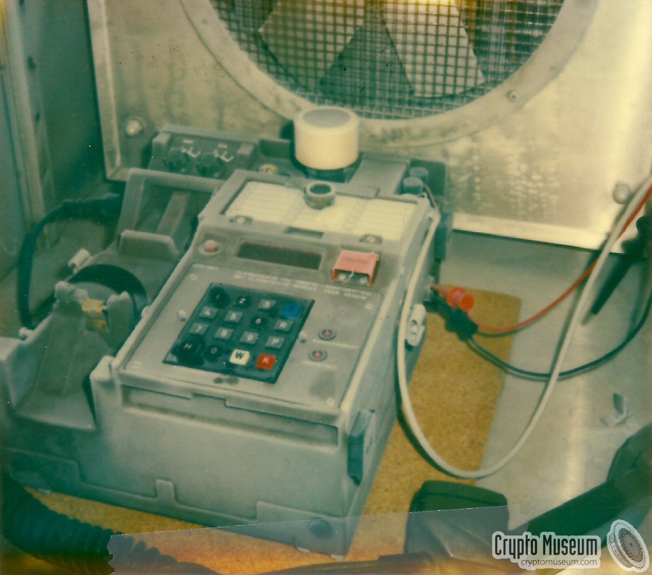
Spendex-50 also had to be able to operate under military temperature
conditions, such as extreme heat and extreme cold.
All temperature tests were conducted by Philips Usfa themselves is a special
climate room. The image on the right shows the Spendex-50 at -40° centigrade.
|
|
|
|
As the images of the cold-test were taken around 1983 with an analog camera
under poor lighting conditions,
their quality is somewhat substandard and blurry.
They do show however, that after turning the unit on at -40°C,
it was still working. And so it also passed this test.
|
All military equipment has to be water-proof to some extent.
It must withstand rain and in some cases even has to be submersable.
Spendex-50 was, of course, no exception to this rule.
Rain tests were usually carried out by Philips Usfa themselves
at their premises in Eindhoven. Although hardly any photographic evidence
of the work at Philips Usfa has survived, we were very pleased by the donation
in 2011 of a series of slides by a former Spendex-developer [1].
The image on the right shows the Spendex-50 undergoing a rain-test
in an improvised setup.
|
|
|
|
Rain tests were usually carried out in Usfa's own backyard, just like they
did several years earlier during the development of the
Ecolex-X cipher machine.
More images of the spendex-50 rain-test below. Like the images of the
cold-test, they were taken nearly 30 years ago with an analog camera.
Nevertheless, their quality is remarkably good after all these years.
|
|
Spendex-50 is housed in a strong die-cast aluminium enclosure in NATO
olive green colours, that is accessible from multiple sides as shown
in the images below. For safety (EMC/EMP) and security (crypto) reasons,
it is highly compartimented, at the bottom as well as at the rear.
|
The interior of the compartments at the rear side of the device
can be accessed by releasing 14 hex bolts at the rear, after which the
entire rear panel – including the carrying grip – comes off.
There are four compartment as shown in the image on the right:
(1) a highly efficient
SMPS (switched-mode power supply)
that converts the external
24V DC into the voltages required by the circuitry,
(2) telephone line protection by means of
gas-filled surge arresters,
(3) sockets for the FILL and CIK interfaces with filtering,
and
(4) handset and peripheral interface terminals.
|
|
|
|
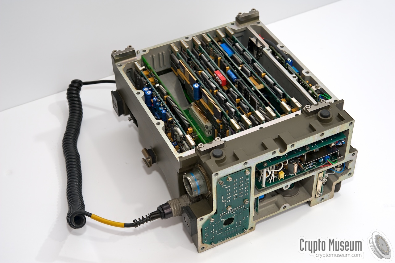
All further electronic circuits are located at the bottom of the unit. Removing
the bottom panel provides access to the line interface,
the analog sound processing, the CPU, the crypto-heart and the memory.
All PCBs, except for the line interface (CDS), are connected
to a common backplane.
|
The bottom section can be accessed by releasing 18 hex bolts
at the bottom, after which the panel can be taken off. The image on the
right shows a Spendex-50 unit of which the rear and bottom panels have been
removed. At the far end is the
line interface (CDS) which – for safety
reasons – is located in a separate compartment. Also at the far end is
a tamper switch,
which ensures that all crypto keys are purged when the case is opened.
The largest compartment has room for 10 PCBs – numbered 1 thru 10 –
which can be slotted into a backplane. Note that boards 3 and 4 are missing.
|
|
|
|
In the first prototype, all 10 slots were used.
During development however, some of the circuits (and their boards)
were redesigned serveral times, as a result of which both the CODEC and
the crypto KEY generator – each of which occupied two boards –
could each be fitted on a single PCB.
|
PCB (1) is the Delta Modulator.
It holds the AF amplifiers
and two purpose-built OQ-2229
Continously Variable Slope Delta Modulators (CVSD),
that were manufactured by Philips for internal use only,
hence the OQ-numbering.
The entire unit is controlled by a CPU – located on
board (8) –
that is built around an Intel 8085 processor running at 6 MHz.
It is accompanied by 2 EPROMs of 32KB each and 4KB of
RAM.
Next to the CPU is the bubble memory –
board (9) – in which the actual
cryptograpich keys are stored in encrypted form.
This board takes a double slot.
|
|
|
|
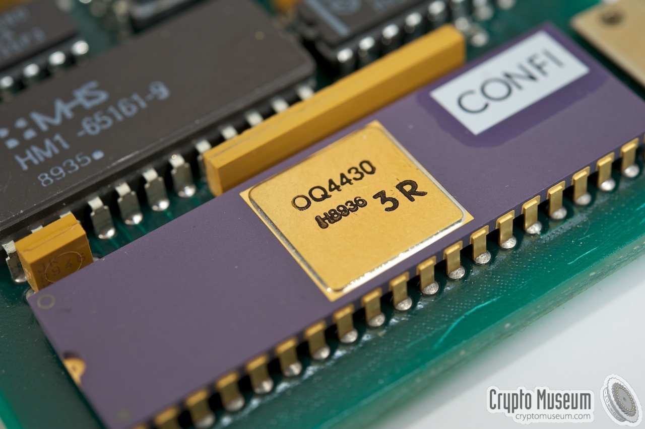
The most interesting part of every cryptographic device is arguably the
so-called Crypto-Heart. In the Spendex-50, the crypto-heart takes the
form of a single PCB in slot number 5.
|
The image on the right shows a close-up of one of three
OQ-4430 crypto-processors,
designed by Philips Usfa. The same chip was used in the
Spendex-40.
According to the date stamp on the chip, it was manufactured mid-1989.
At the time, these chips were classified as confidential.
The crypto-heart contains three more-or-less identical circuits,
each built around an OQ-4430 with 2KB of RAM. In a full duplex system, one
crypto-unit is used for reception, whilst the other two are used for
fail-safe transmission, raising an alarm if their outputs are different.
|
|
|
The OQ-4430 is a proprietary in-house developed chip that contains Philips'
own implementation of the highly secret
SAVILLE cryptographic algorithm,
that had been developed in the late 1960s, jointly by
GCHQ in the UK
and the NSA in the USA.
In fact, Philips was the first company outside the US and the UK
to be licensed to implement the
SAVILLE algorithm
in their own hardware chip.
Although SAVILLE
is also used in other crypto phones –
such as the Spendex 40
and the STU-II –
Spendex 50 is not interoperable with them,
as it uses wideband CVSD modulation, whereas the others are based on
a narrowband LPC-10 vocoder.
|
|
As Spendex-50 uses symmetric encryption, it has to hold key-pairs for
every possible connection in the network. In a network of, say, 2000
subscribers, this would quickly exhaust the available memory. This was
partly solved by using a clever exchange-assisted key-distribution scheme,
which greatly reduced the memory needed for the key-pair tables, known as
Key-Cube Key
[5].
|
The major problem however, was the storage space needed for the keys,
as large non-volatile memory systems were not commonly available at the time.
This problem was overcome by using a 1Mbit 7110 bubble memory unit that had
just become available from Memtech (later: Intel).
Like with contemporary harddiscs, it was virtually impossible to manufacture
an error-free bubble memory unit.
Usable sectors were thefore listed on the label
as a series of hexadecimal numbers, in which an
'F' represents 4 usable sectors. Any bad sectors are masked-out
in the software.
|
|
|
As bubble memories were not very reliable — a good sector might suddenly
become a bad one — Philips engineers added
some level of redundancy, to make it possible to 'repair'
and 'defects' in the field, entirely in software.
As the buying price for the Intel 7110 was several thousand Dutch
Guilders (NLG) at the time,
it added considerably to the overall cost of the unit, which is one
of the reasons why the Dutch Department of Defence
reduced the ordered quantity to 750 units.
Bubble memory was never really popular. Soon after its introduction,
larger flash memory devices became available, which were more reliable and
much cheaper. Although this was too late for the Spendex-50, it would have
made sense to do a midlife upgrade several years later,
and redesign the key storage board with flash memory. This was in fact
suggested by Philips engineers, but was declined by the DoD,
as they didn't want to go through the approval procedure again [1].
|
Although a Spendex-50 terminal can be used on its own — two units can be
connected directly back-to-back —
it was intended
for the ZODIAC tactical network
of the Dutch armed forces.
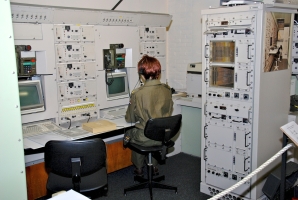
After ZODIAC was phased out (2004-2007),
a working HSA telephone exchange, complete with all
cryptographic equipment and a number of operational
Spendex-50 units — DBTs — was installed
at the Royal Dutch Signals Museum.
➤ More about ZODIAC
|
|
|
When setting up a call via the digital telephone exchange of ZODIAC,
the user had to dial the 13-digit number of the other party, which consisted
of a 6-digit prefix, and a 7-digit subscriber number. The subscriber
number was not tied to the geographical location of the subscriber, but
to his function in the military hierarchy, in such a way that it could be
'guessed' intuitively. This deterministic method is part of the EUROCOM
standard and is fully described in STANAG 1 5046.
The 6-digit prefix is also known as the NIAC field, and consists of two
3-digit fields, here shown in red and green respectively. The first part
is the Nationality Indicator (NI) of which the first digit is always '9'.
The remaining digits (XX) represent the nationality.
The second part is the Area Code (AC) of which the first digit (N) is the
network number (e.g. army corps) and the remaining digits (YY) represent
the nationality of (N). If XX and YY are identical, the subcribers are
assumed to be 'local' If they are not identical, NYY is assumed to be a
guest on 9XX's network. The definition of the NIAC field is part of the
EUROCOM standard and is fully described in draft-STANAG 4214.
|
 |
-
STANAG = Standard NATO Agreement.
|
|
An adapted version of Spendex 50 was made available for use by other
NATO countries. It was known
as DWBST 55 and as UA-8238.
DWBST stands for Digital Wide-Band Secure Terminal.
In appearance it was identical to the regular Spendex 50,
and complied with EUROCOM standards.
|
It was advertised as a stand-alone tactical wide-band secure
voice terminal designed for secure communication of speech and data (either
digital or analogue), operating at 16 or 32 kbits/s [5].
The terminal enables a subscriber to set up a fully automatic
secure end-to-end connection
for digital communication with another UA-8328 — or
compatible equipment — in the network. The terminal can also be used as an
automatic telephone for plain-language communication.
For the compression of speech (80-3400 kHz), i6 uses delta modulation
(CVSD) at 16/32 kbit/s.
|
|
|
Data can be transferred at 2400 baud (asynchronous).
For secure traffic it can hold up to 18 sets of common net keys which
can be pre-loaded into any terminal. It can also be used for up to 3400
subscribers in a network, in which case key pairs are stored
in its internal bubble memory.
According to Jane's Military Communications catalogue of
1986 [5],
DWBST 55 was in production in 1986, but it is
doubtful wether any Spendex-50 units were ever sold under this name.
|
|
Approximately 10 years after the conception of the Spendex 50,
the US Army and US Navy introduced a similar device, with nearly identical
specifications: the KY-68 Digital Subscriber Voice Terminal (DSVT).
The device is similar is size, weight, specification and operation.
|
The image on the right shows a typical KY-68 unit.
Like the Philips Spendex 50 it uses CVSD modulation, biphase signaling
and 8-bit cyclic permutable codewords (CPC).
The main differences are the lack of a display and CIK.
The DSVT was
introduced in 1992 and was gradually phased out in 2010, when it was
replaced by the (incompatible)
Secure Terminal Equipment (STE).
➤ More information
|
|
|
|
The Spendex 50 is powered by a DC voltage between 20 and 32 V –
typically 24V –
that should be applied to the three-pin socket at the right side.
It can briefly withstand a voltage up to 40V and power surges up to 250V.
The pinout is as follows (looking into the socket):
|
- (+) 20-32V DC
- (-) 0V
- not connected
|
|
|
A standard 5-pin U-229 socket (U-183/U)
is present for connection of a (US-standard) handset with speaker, microphone
and push-to-talk (PTT) switch. Note that the microphone should be of a
dynamic type, as it is used by the Spendex 50 as (ring) buzzer.
|
- GND
- SPK
- PTT
- MIC
- not connected
|
|
Device Secure digital telepohone set Purpose Digital military voice and data communications Model Spendex 50 Name Digitaal Beveiligd Telefoontoestel (DBT) Designator UA-8256 Manufacturer Philips Usfa Development 1983-1987 Introduction 1987 Country Netherlands Wiring WD1/TT (2-wire), Eurocom D/I Signalling CPC Speech 16 kb/s, Delta Modulation 1 Encryption SAVILLE Frequency 80 - 3400 Hz (analogue data 300 - 3400 Hz) Keys NET (18 sets), KC 2 (3400 subscribers) Fill DS-102 compatible fill device, or OTAR Power 20 to 32V DC Quantity 750 Price EUR 20,000 (1983)
|
TA-5912 Spendex 50 (DBT) with handset and cover CX-4657 Power cable (in bag) KY-6388 Classification Module (CM or CIK) - Overlay for DATA mode - Overlay for COMSEC mode MX-6390 Mounting panel MX-6390 Shock-mounting IK001433/1 Instruction card DBT general IK001433/2 Instruction card DBT COMSEC
|
-
Also known as Digitally Controlled Delta Modulation (DCDM) or
Continuous Variable Slope Deltmodulation (CVSD).
-
KC = Key Cube.
|
|
The Spendex 50 is known under the following names and designators:
|
Spendex 50 Philips model number DBT Digitaal Beveiligd Toestel (Digital Secure Device) DBT Digitaal Beveiligd Telefoontoestel (Digitial Secure Phone) UA-8246 Philips Usfa internal designator TA-5912 Dutch Army designator DWBST 55 Digital Wide-Band Secure Terminal (NATO) UA-8238 NATO-specific variant NSN 5805-17-055-9132
|
|
CIK
|
|
Crypto Ignition Key
Unique physical key module that is paired with the equipment and contains
part of the cryptographic key(s). Also known as Classification Module,
CLASMOD or CM.
|
|
Clasmod
|
|
Classification Module  CIK CIK
|
|
CM
|
|
Classification Module CIK
|
|
CVSD
|
|
Continuous Variable Slope Deltamodulation
Method for converting analogue sound into a 1-bit data stream, in which
each bit has the same weight. It is often chosen over
Pulse-Code Modulation
(PCM) because of its high resilience to bit errors (up to 10%).
➤ More
|
|
ZK
|
|
Zeroizse Key
Randomly generated key, held in battery-backed RAM inside the terminal,
that is used together with the Crypto Ignition Key (CIK) to encrypt the
Traffic Encryption Keys (TEKs) stored in the bubble memory of the Spendex 50.
|
|
|
-
HSA = Hollandse Signaal Apparaten. This manual was re-issued
to the Dutch Army in 2001 after HSA had taken over Philips Usfa BV.
Strickly speaking, the Spendex 50 was handled by Philips Crypto BV at
this time and not by HSA, but HSA had the overall responsibility for the
Army's ZODIAC communications system.
|
- Mathieu Goudsmits — Spendex-50 developer at Philips Usfa
Interview, Crypto Museum. July 2011.
- Fysisch en Elektronisch Laboratorium TNO,
Definitie rapport taktisch LAN demonstratie (Dutch)
Unclassified. June 1990, p. 28 - Het DBT interface.
- AJW van Daal & P van der Vlist, DELTACS - a versatile tactical communication system
Philips Telecommunicatie Industrie BV (PTI), Hilversum (Netherlands), 1984.
Reprint from Philips Telecommunication Review, Vol. 42, No. 2, pages 74-89.
- Royal Dutch Signals Museum
Museum Verbindingsdienst.
- Jane's Military Communication 1986
ISBN: 0-7106-0824-1. p. 446.
- CJA Jansen, Classical Key Management
Proceedings of the Fifth Symposium on Information Theory in the Benelux,
Aalten, The Netherlands, 24-25 May 1984, pp. 94-101.
- US Patent 4607137, Method of distributing and utilizing enciphering keys
CJA Jansen, AJM vd Pas, P vd Vlist, F Hafkamp. US Philips Corporation.
Filed 13 April 1984, issued 19 August 1986.
- Wikipedia, Bubble memory
Retrieved May 2012.
|
|
|
|
Any links shown in red are currently unavailable.
If you like the information on this website, why not make a donation?
© Crypto Museum. Created: Saturday 16 July 2011. Last changed: Tuesday, 07 October 2025 - 15:12 CET.
|
|

|
|
|