|
|
|
|
|

|
|
← Fialka USSR M-125-3MR3 →
Checklist for the M-125-3MP3
Each M-125 Fialka machine
was supplied with a checklist when it was released by the factory.
This list provided details of the quantity and nature of each
item that was supplied and a stock number that could be used when ordering
replacement parts. There was no date on the list.
|
The image on the right shows a rare example of a checklist that was
found with a
Czech Fialka M-125-3MR3
(Russian: М-125-МР3). For privacy
reasons, all signatures have been removed [1].
The serial number of the machine was written in the top right corner of the
checklist, whilst the signature of the person responsible for releasing the
items was at the top left. Three signatures were at the bottom of the
form: one for a representative of the manufacturer, one for the approval
department and one for the customer.
The checklist can roughly be divided into three sections. The first
section (items 1 to 11) refers to the Fialka machine itself and the accessories
that are stored inside the metal dust cover. The second section (items 12-17)
refers to the Power Supply Unit (PSU) and the cables that are needed
for connection to the Fialka and a power source.
The third section (items 18-22) finally lists the various spare parts,
maintenance tools and separate dust cover and shock absorbing mat
that were originally supplied with the machine.
|
|
|
Please note that not all items of this list have been recovered by
collectors yet. Whilst most items are known by now, some parts, such as the
canvas cover, the shock absorbing mat and the wooden box with the larger
tools, remain a mystery.
Fialka checklists are extremely rare and, as far as we know, the one shown
here is the only surviving example. We should like to thank Tom Perera
for providing us with a photograph of his checklist and permission
to share it with you [1]. Further details and translations are provided in the
Fialka M-125 Reference Manual
[3].
|
|
Below is a rough translation of the Russian items on the checklist.
Please note that in some cases it was difficult to translated the rather
cryptic items names, but with help of Daniel Kula of the former
Czechoslovakia [2] we have been able to identify most items.
Where possible we have provided links to further details from the listed
items below.
|
-
These items are located in the metal dust cover of the machine.
-
These items are located in the cable storage compartment of the PSU.
-
The individual tools were listed on a separeate form that we haven't found yet.
-
ZIP is the abbreviation of 'Spare parts and accessories' (see below).
-
The list might also refer to the Standard Power Supply Unit.
-
The 2nd box has not yet been identified.
It might refer to the old style paper chad box.
|
|
|
ZIP
Spare parts and accessories
|
|
|
|
Item number 20 in the list, ZIP (Russian: ЗИП),
is the abbreviation of the Russian expression
Запасные части И Принадлежности (Spare parts and accessories).
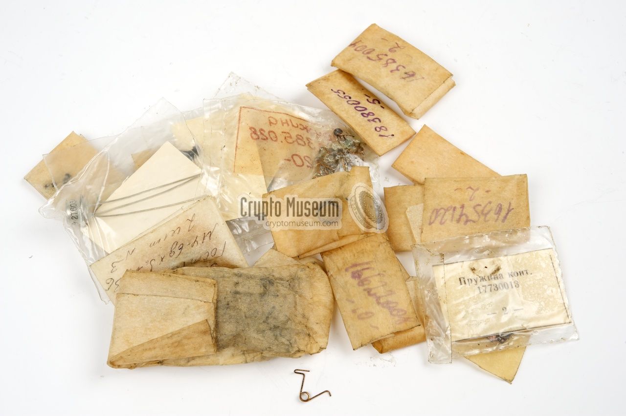
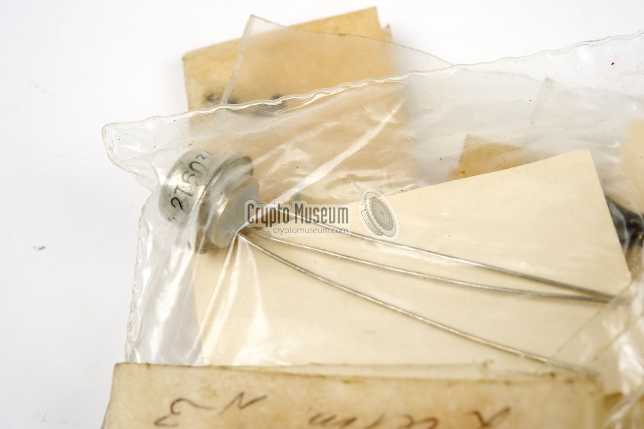
It refers to a wooden box that contains mechanical spare parts (brackets,
pawls, springs, etc.) as well as electronic spare parts
(transistors, diodes, contacts, fuses, etc.).
The first complete ZIP boxes were discovered in 2015.
|
Prior to that, we found some of the contents of the ZIP box.
The image on the right shows a small collection of spare parts
such as notches, pawls, levers, screws, knobs, springs,
transistors and contacts (for the adjustable wheels).
Each item was wrapped in a numbered piece of paper.
In reality however, the Fialka appeared to be so reliably that mechanical
spare parts were hardly needed. As a result, repair centres all over the
Eastern-Block countries had warehouses full of them by the end of the
Cold War. These have since been scrapped, but some have
survived.
|
|
|
- Tom Perera, Photograph of Fialka M-125-3MR3 checklist
Received January 2006.
- Daniel Kula, Personal correspondence
Help and explanation of Russian key words on the checklist.
May 2006.
- Paul Reuvers and Marc Simons, The Fialka M-125 Reference Manual
Copyright 2005-2009. Version 2.0, June 2009. ISBN 978-90-79991-01-3.
|
|
|
|
Any links shown in red are currently unavailable.
If you like the information on this website, why not make a donation?
© Crypto Museum. Created: Wednesday 20 August 2014. Last changed: Friday, 23 February 2018 - 20:41 CET.
|
 |

|
|
|


![Example of a checklist as released with a Polish Fialka M-125-3MR3 [1]](img/checklist.jpg)