|
|
|
|
|

|
|
USSR Rotor Fialka
Three-point circuit · binary rotator
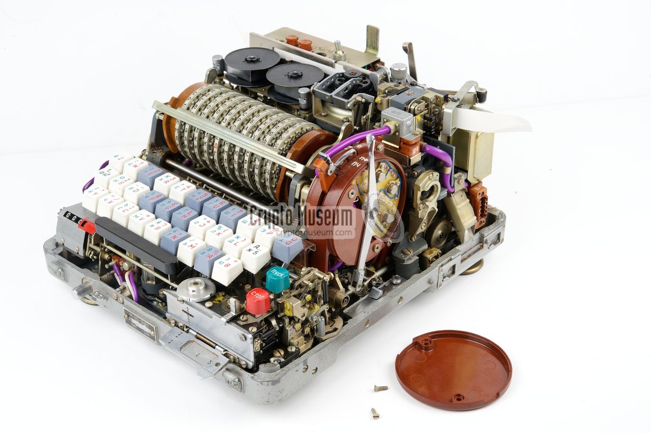
The Magic Circuit is an electronic circuit, mounted inside the
MODE-selector at the right hand side of the M-125 (Fialka).
It is connected to four wires of the
reflector and also to the keyboard.
It ensures that a letter can be enciphered into itself,
which is normally not possible when using a reflector.
In German, the circuit is known as Driepunktschaltung (three-point circuit). 1
|
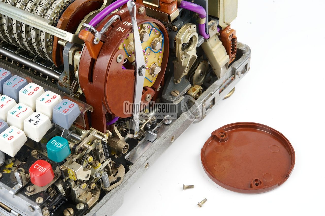
The Magic Circuit consists of a few transistors, diodes and resistors
that are mounted on a curved epoxy carrier, similar to a printed
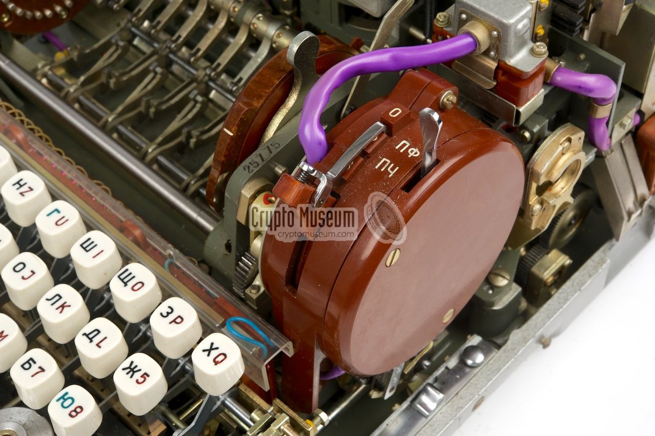
circuit board (PCB). It is located inside the
big red circular bakelite enclosure
to the right of the entry disc, that also holds the MODE selector.
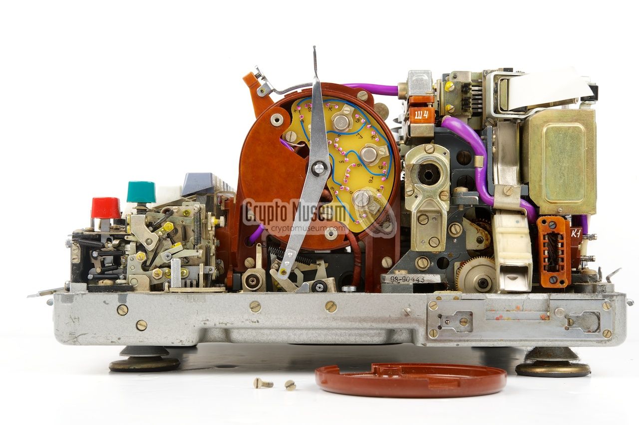
The image on the right shows the red bakelite enclosure of which
the side panel has been removed. This gives access to the Magic Circuit
of which the three transistors are directly visible.
In the earlier versions
of the machine, it was made with larger transistors
on a bakelite panel.
|
|
|
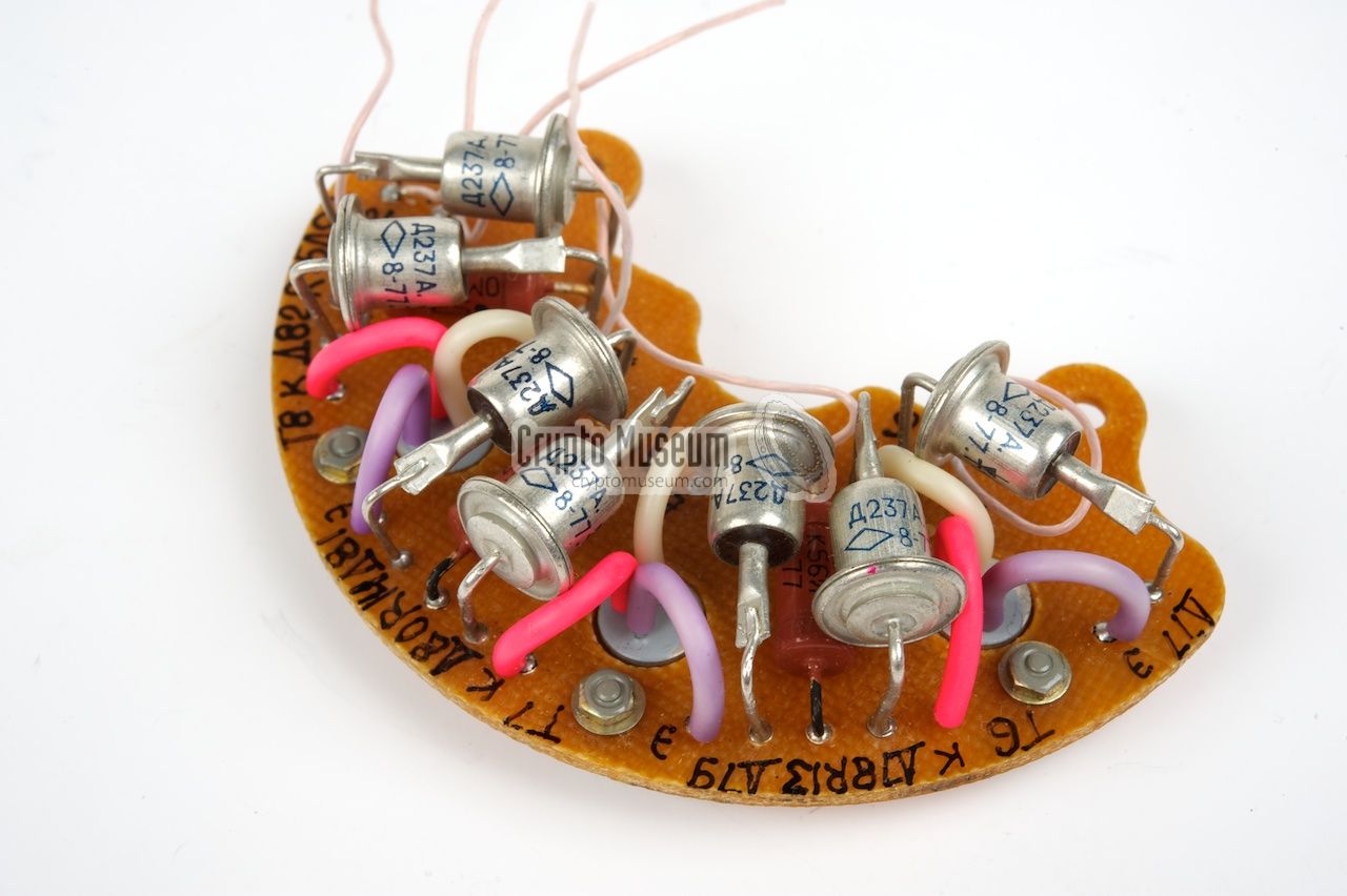
This older version is shown in the first images below. The rather large
Russian P701A transistors are embedded
in a pre-shaped bakelite carrier. The other
components are mounted at the reverse side.
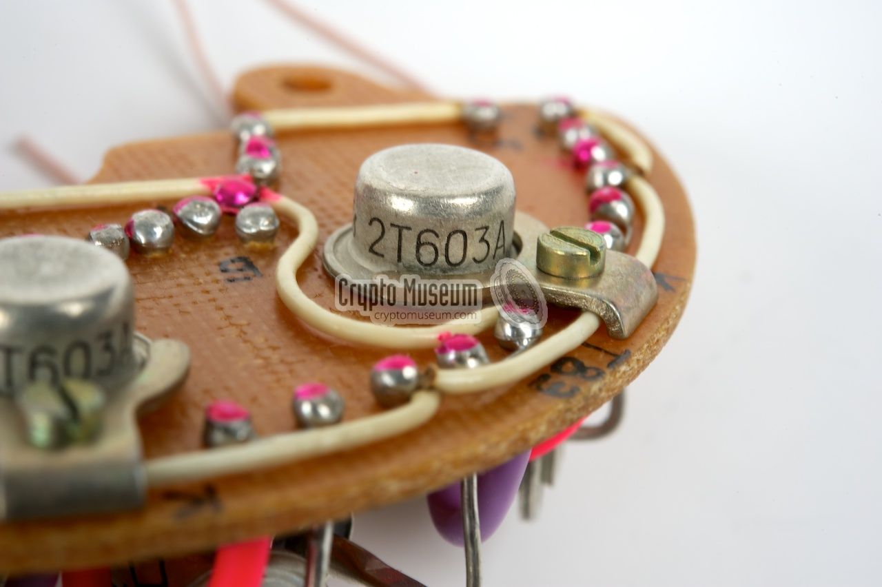
In a later version of the machine, the transistors have been replaced
by the smaller Russian 2T603A, mounted on
an epoxy fibre carrier.
This version is visible in the image above.
The use of transistors in this machine is remarkable, as they had only just
been invented when the machine was first introduced (1956). It shows
the technological skills of the Russians in those days, which is further
illustrated by the cleverness of the circuit itself. Many similar
devices in other countries (but also in Russia) used valves (tubes)
well into the 1960s and even in the 1970s.
|
 |
-
'Magic circuit' is the nickname we gave this circuit when we first
investigated a Fialka machine in 2005. At the time it was not immediately
obvious what this circuit does. Although we now know that the official
name was three-point circuit,
we decided to keep the name 'magic circuit' to emphasize its special
characteristic.
|
Like with the German Enigma machine, the
Fialka has a reflector (German: Umkehrwalze or UKW)
to the left of the cipher wheels. It connects the contact
pins together in pairs, and makes the machine reciprocal (i.e. reversible,
or symmetrical).
When an electric current from the cipher wheels hits one contact of
the reflector, it is send back into the drum via the paired contact.
The drawing below shows a simplified circuit diagram of such a reflector.
A nasty side effect of using a reflector is that the return path of
the current is always different from the entry path and, hence, a letter
can never be encoded into itself.
This was considered a
weakness of the Enigma.
With Fialka this is solved by 'breaking' one wire pair (13-16)
and using one of the contacts (13) to override the encoding matrix,
causing a letter to become itself.
This is called the plaintext enable signal.
This leaves us with one unconnected wire (16). And this is where the
'magic' bit comes in. By breaking another wire pair (18-24), the three
remaining wires (16, 18 and 24) are connected to the 'Magic Circuit',
as shown in the diagram of the M-125 reflector below.
The Magic Circuit is in fact a binary rotator (German: Dreipunktschaltung)
that combines the three signals in a special manner. This is best explained
by the diagram below. If the current enters the reflector at contact (18),
it is returned from contact (24). However, if the current enters at contact
(24), it is returned from contact (16). And finally, when it enters at (16)
it is returned from (18).
As a side-effect, the machine partly loses its reciprocity, but this is
simply solved by swapping two of the three lines when in Decoding mode.
Swapping two lines has the effect of rotating the other way around, as
illustrated in the rightmost triangle above. In the circuit diagram above
this is shown as a yellow box (MODE switch). In decoding mode, two wires
(16 and 24) are cross-connected. This is why the Magic Circuit
is mounted inside the enclosure of the MODE selector.
|
The circuit diagram of the Magic Circuit is given below.
Three similar circuits, based around T6, T7 and T8, are cascaded.
The output of each circuit is connected to the input of the next one,
via a diode. The output of the third stage (T8) is looped back to the
input of the first stage (T6) via diode D82.
This results in the triangular circuit that is described above.
All three lines of the Magic Circuit (i.e. pins 4, 5 and 6)
are bi-directional. They can be inputs as well as outputs.
Pin 18 of the reflector is connected directly to pin 6 of the Magic Circuit.
Pins 16 and 24 of the reflector are routed via unit 8 and 9 of the MODE switch.
In plain-text mode (MODE selector set to 0) they are left unconnected.
In Decoding mode (MODE selector set to P), pin 16 of the reflector
is connected to pin 5 of the Magic Circuit and pin 24 of the reflector
goes to pin 4 of the Magic Circuit.
In Coding mode (MODE selector set to 3),
reflector pins 16 and 24 are swapped.
The system uses negative logic.
When pin 6 of the Magic Circuit is pulled low by a current from pin 18 of
the reflector, the NPN transistor T6 will conduct as it's base is pulled
high by the 560 ohm resistor. As a result, the collector of T6 will be
pulled low, which also pulls the base of T7 low. T7 will therefore not
conduct and the diode (D79) will pull the emitter down. So, pin 5 will
be low (i.e. the signal from pin 6 is 'reflected' via pin 5).
As T7 is not conducting, the base of T8 will be high,
so T8 will be conducting, resulting in a high on pin 4.
As the end of the circuit (D82) is looped back to the beginning,
the above is true for any of the three lines. In other words: a low
on line n will result in a low on line n+1
and a high on the remaining line.
Diode D83 is not connected to the rest of the circuit.
It is probably only part of the Magic Circuit for convience of wiring.
The cathode of D83 is connected to pin 13 of the reflector.
When this line is driven low, it pulls the plain-text enable line
of the mechanical 5-bit encoder (mounted under the keyboard) low,
which will cause the plain-text 5-bit code to override the diode matrix.
As no signal is returned into the drum, this doesn't interfere with
the rest of the diode matrix. It is this signal that can cause a
letter to be enciphered as itself.
|
The above description and circuit diagrams describe the older
M-125 machine.
Although the Magic Circuit in the later
M-125-3 is identical,
the wiring of the reflector is far more complex, as 20 of its lines
are routed via the 30 ↔ 10 reduction switch. For further details
about the exact wiring of that reflector,
please refer to the Fialka Reference Manual [A].
|
|
|
|
Any links shown in red are currently unavailable.
If you like the information on this website, why not make a donation?
© Crypto Museum. Created: Monday 07 July 2014. Last changed: Wednesday, 10 July 2024 - 06:24 CET.
|
|

|
|
|