|
|
|
|
|

|
|
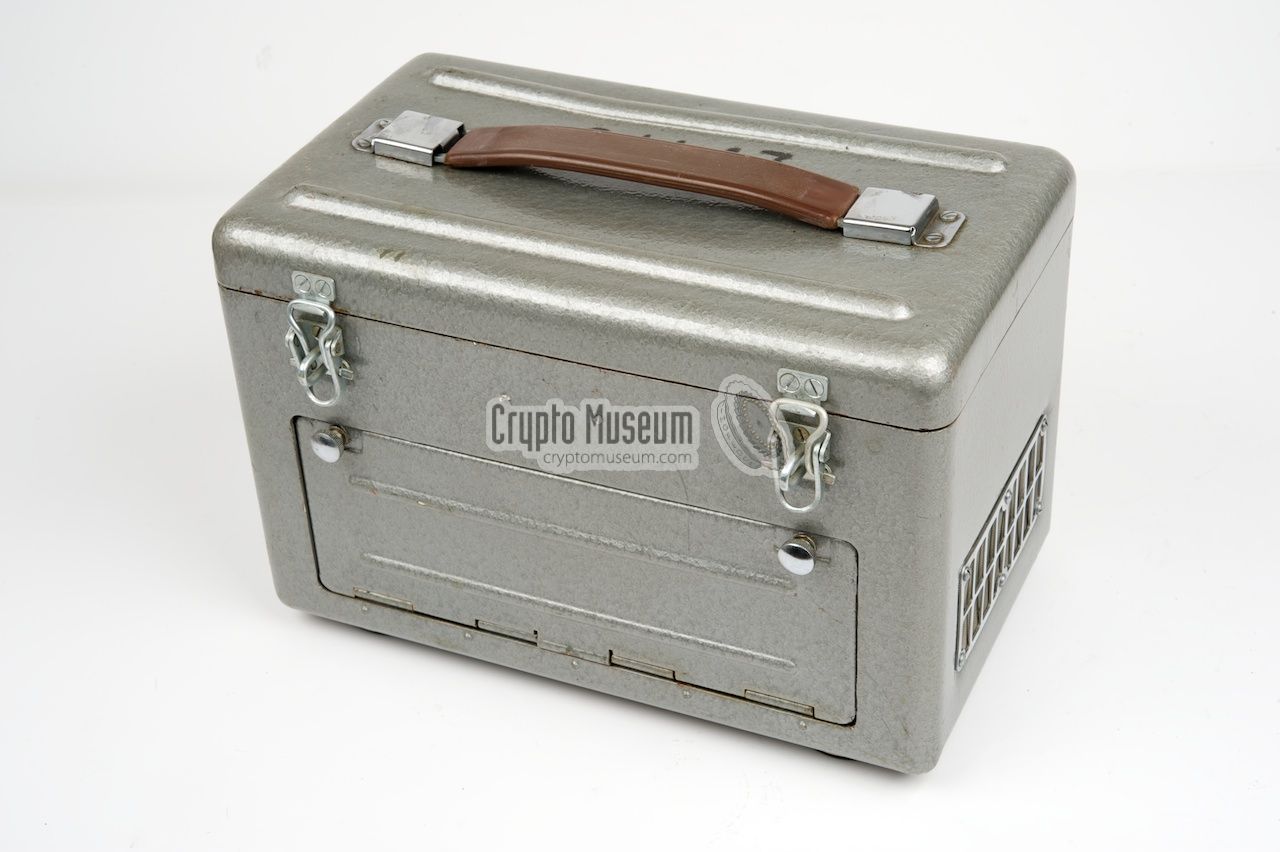
USSR Fialka BPK-125 →
The one shown here is the standard variant of which the model number
is currently unknown. It was supplied with the
Fialka cipher machine
in most countries of the Warsaw Pact, including East Germany (DDR) and
Czechoslovakia. It was also supplied with the later
M-105 (Agat).
The standard Power Supply Unit (PSU) measures 26 x 17 x 17 cm
and was designed for use with cipher machines that were driven by a
24V DC motor. It allows them to be powered from the AC mains and
supports a wide range of AC voltages (90-260V) in steps of approx. 10-30V.
|
|
|
|
So far, we have encountered two slightly different versions of the
standard PSU:
|
- Older version with separate ON/OFF switch
On the older version of the PSU,
a separate ON/OFF switch is
present. It is located to the left of the mains voltage selector
at the bottom right of the control panel. Furthermore, the text on
the control panel
is printed in a large - rather fat - typeface.
This version generally has a 5-digit serial number that is printed
on the top lid of the case.
- Newer version with combined ON/OFF switch
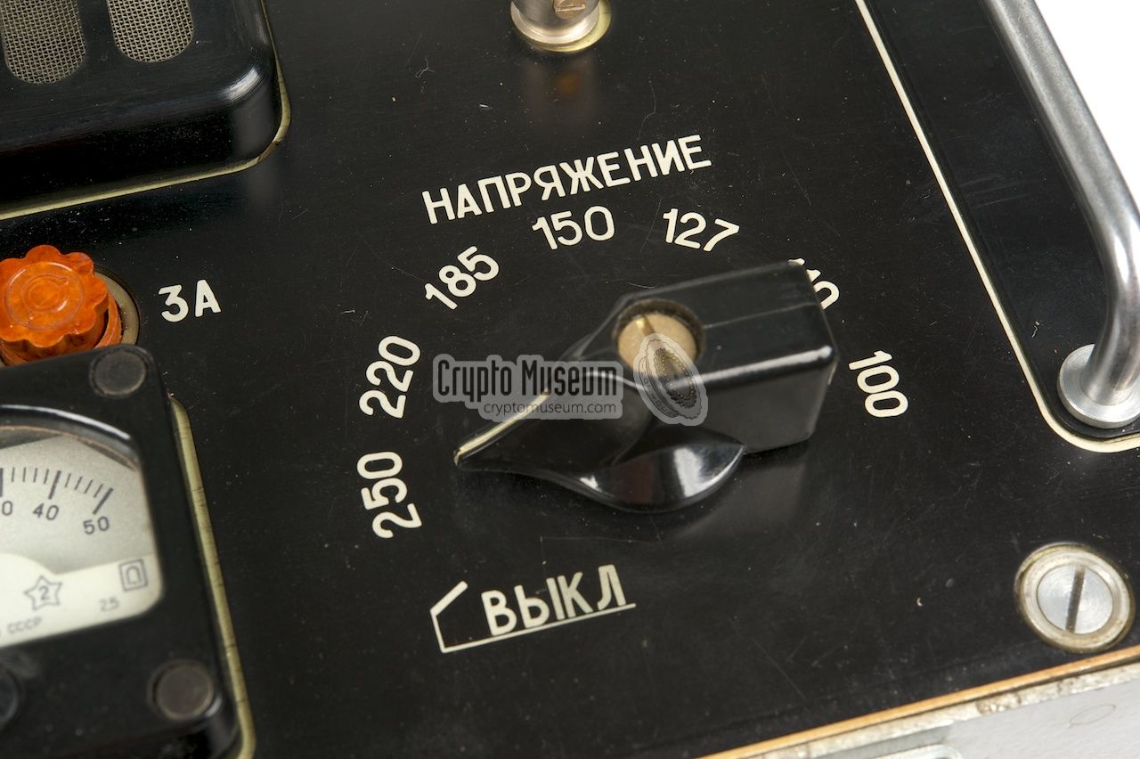
On a later version of the PSU, the
ON/OFF switch is combined with
the AC voltage selector. In the leftmost setting of this selector, the
PSU is switches OFF. Furthermore, the text on the
control panel is
printed in a smaller typeface and with some devices, the
circuit diagram is printed inside the
top lid. This version generally has
a 7-digit serial number in the 98-xxxxx format.
The same version of PSU was used with the
M-105 (AGAT) cipher machine,
in which case the serial number was in the format 97-xxxxx.
|
The diagram below should help to understand the controls and connections
of the PSU. They are not nicely arranged in a logical and safe manner,
as one would expect with a device that is connected to the mains.
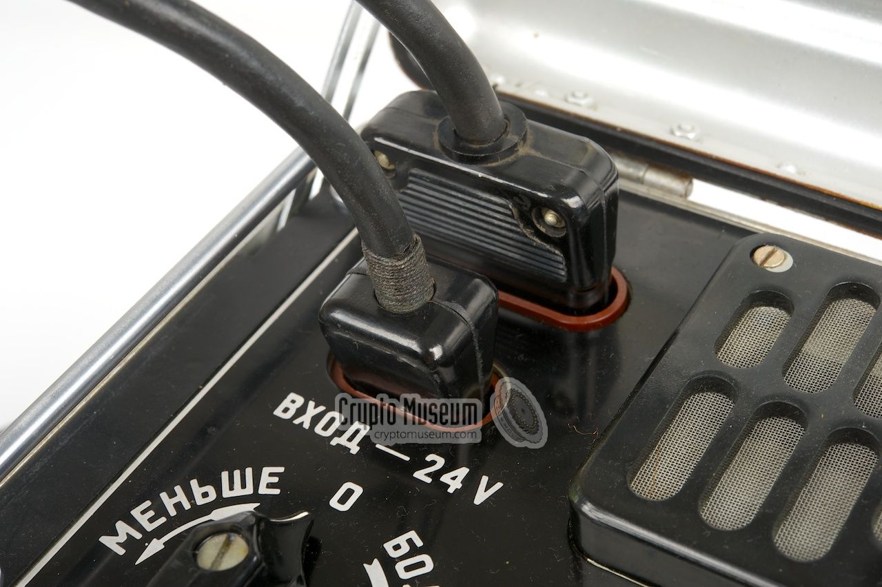
At the top left is the socket for connection to the AC mains. The correct
input voltage is selected with the 8-position rotary switch at the bottom
right. On the later version of the PSU, this selector also functions as the
ON/OFF switch. In the leftmost position, the PSU is switched OFF.
The older version has a separate ON/OFF switch,
to the left of the selector.
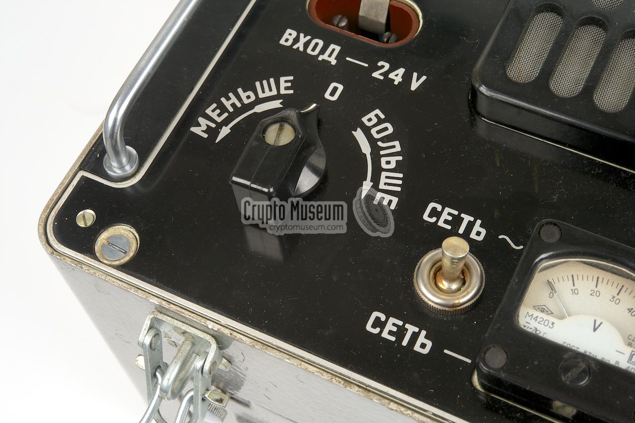
The PSU can also take
its input from a 24V DC source, such as the battery of a (military) vehicle.
If it is available, the 24V DC source is connected to the socket just below
the mains socket at the top left. The toggle switch to the left of the meter
at the bottom is used to select between them.
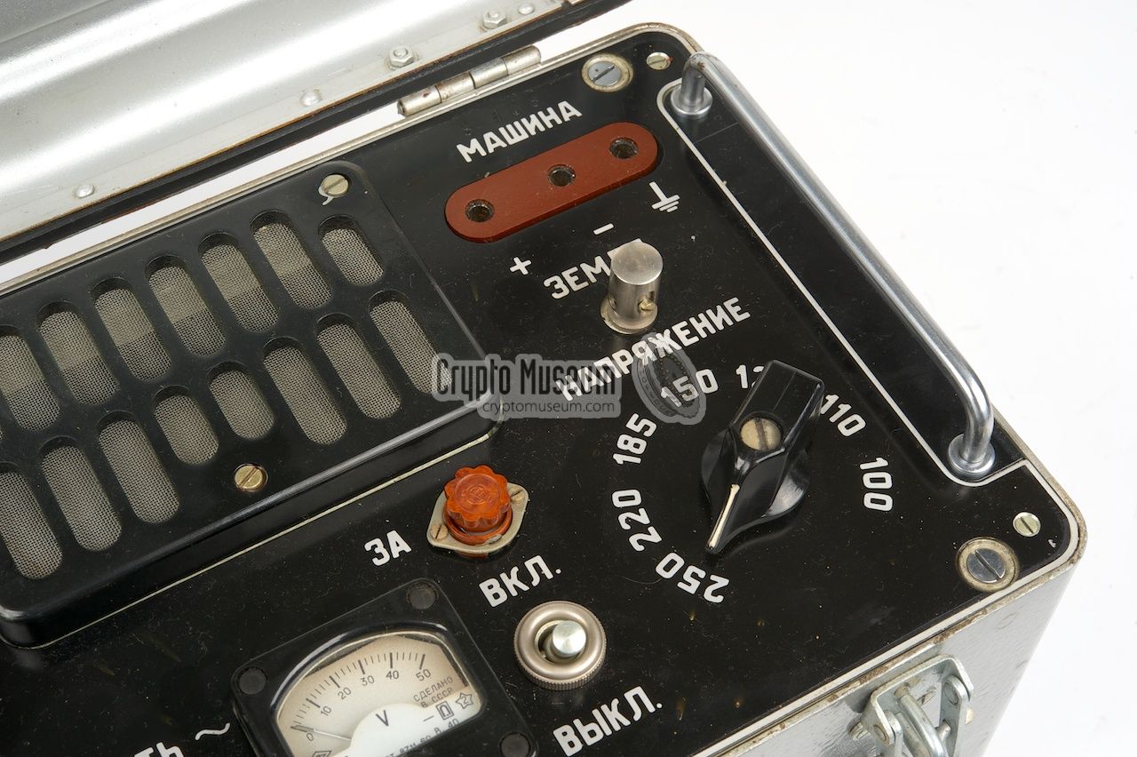
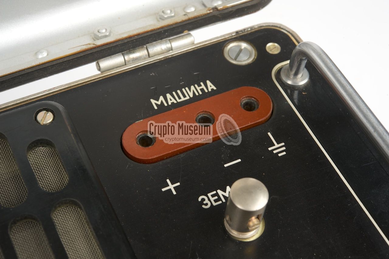
The 24V DC output voltage (i.e. the connection to the cipher machine) is
available at the top right from the socket marked МАШИНА (Machine).
The voltage can be fine tuned somewhat with the selector
at the bottom left, whilst the meter at the bottom is used to monitor the
correct voltage.
|
|
Although the PSU is not a rare item (quite a few have survived destruction),
finding the proper cables might present more of a problem as many of them
have been destroyed after the units were taken out of service. Five cables
were normally supplied with the PSU, but a minimum of two is needed to
operate the machine. Luckily there are some sources for good reproduction cables.
In the description below it is assumed that the PSU is used in combination with
the M-125 Fialka cipher machine.
For use with the M-105 Agat, a different set
of cables might be needed.
|
When in transit, the cables were usually stored in the
special cable compartment
at the front of the PSU.
The hinged lid of this compartment is held in place
by two screws and can easily be opened by hand. A total of five cables were
supplied with the PSU, as shown in the image on the right.
Be careful with these cables as they might have become fragile after
all this time. Once you got them out of the storage compartment,
it might be best to leave them out and store them separately with the
PSU in the future. This will protect the cables against too much bending.
|
|
|
For safety reasons it is advised to thoroughly check the
mains power cable
before connecting it to the mains. As the cable is rather old, the insulation of
the internal wires may have become brittle and might have to be replaced.
Use the mains cable only if you are certain that it is safe.
|
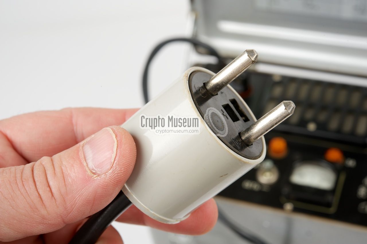
A minimum of two cables
are needed to connect the PSU to the mains and to the
cipher machine. The mains cable
has a standard wall plug at one end and a rather
strange 3-pin female plug at the other end.
Warning: be careful as the
female contacts of
this plug can be touched by hand.
Depending on the version, the wall plug of the mains cable might not fit a
standard European wall socket. This is because the
wall plugs in the East-European
countries have thicker pins. Use an
appropriate adapter
or swap the wall plug
for an approved one if you want to use the cable.
|
|
|
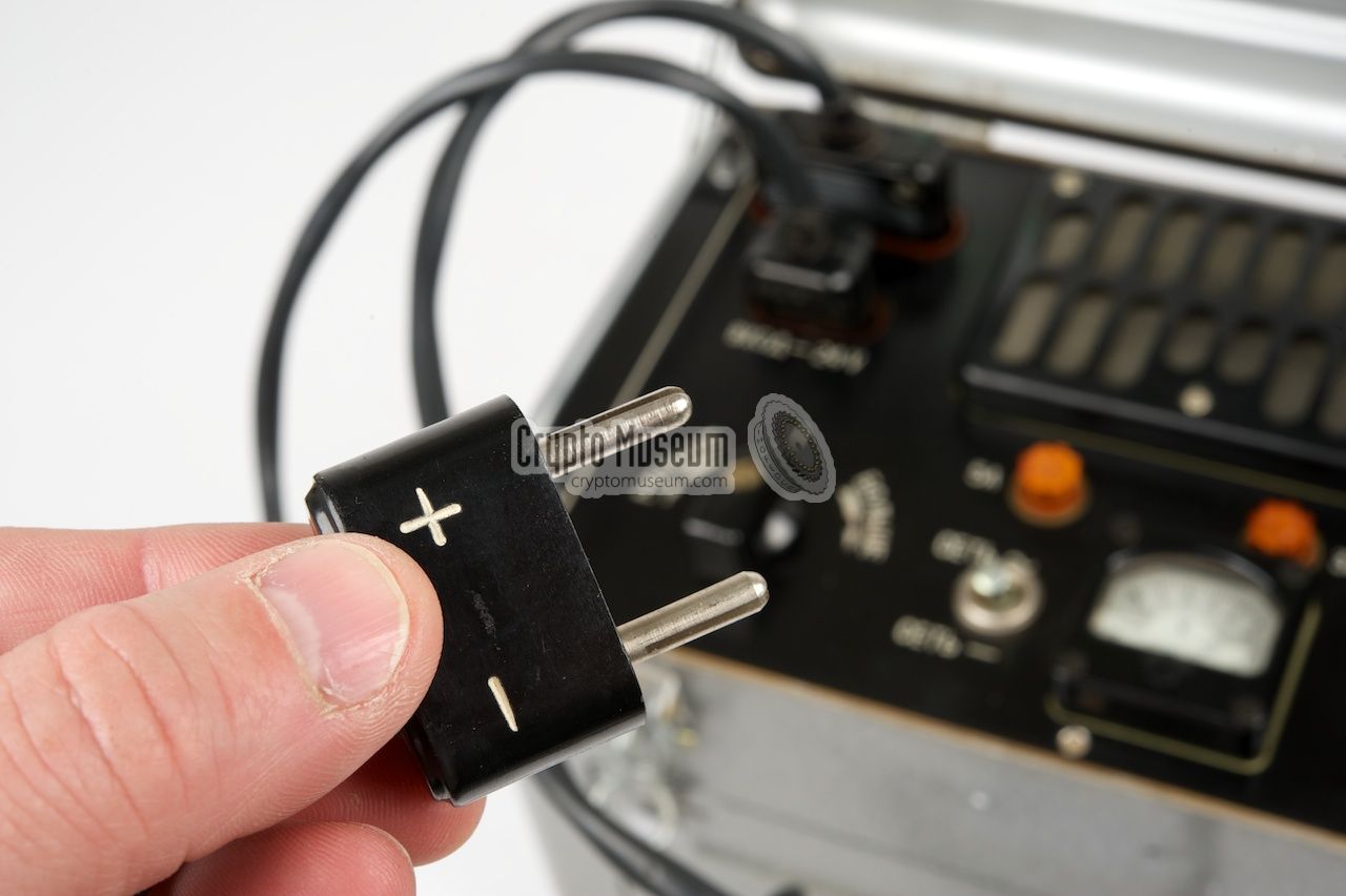
The 24V DC output cable
has a Fialka power plug at one end and a rather strange
3-pin male plug at the other end. This plug mates with the
24V DC output socket
at the top right of the PSU.
Warning: never connect this 3-pin male plug (24V DC) to the 3-pin female plug
(230V AC) of the mains cable. Due to bad design, it fits perfectly, but supplies
the mains voltage to the 24V input of the cipher machine, causing permanent damage
to the cipher machine. Be warned!
|
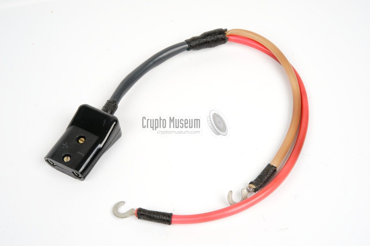
When present, the 24V DC input cable
can be used to supply 24V from the battery
of, say, a military truck, directly to the PSU. It allows
switching between
the AC mains and the DC battery voltage without swapping the cables.
The 24V DC input cable
has a Fialka 24V plug at one end and a 2-pin plug at the
other end. The Fialka 24V plug
mates with the 24V DC input socket at the top
left of the PSU, just below the mains socket. The other one should go to the
24V rail of the vehicle. It should be
marked with (+) and (-) symbols.
Be careful when connecting.
|
|
|
Also be careful not to put this 2-pin 24V plug into a mains wall socket.
Although it fits perfectly, it is not intended for this. If a suitable 24V DC
socket was not available in the vehicle, an extra
battery cable could be
used to connect this plug directly to a car battery or another 24V source.
|
The 24V DC input cable can also be used as an alternative power cable for the
Fialka machine. It allows Fialka to be connected directly to the 24V
rail of a vehicle or directly to a 24V battery.
It can also be used to connect an extra Fialka cipher machine
to the PSU, simply by connecting it
'piggy-back' to the normal 24V output
plug.
Please note that the PSU can only drive one machine at a time.
The 'piggy-back' socket on top of the 3-pin 24V plug (see image)
was normally used for connecting a service lamp.
|
|
|
The last cable that was supplied with the PSU is a short
ground wire.
It allows the ground of the PSU to be connected to the ground of, say,
a vehicle. If the PSU is placed on a metal surface (e.g. a table)
the wire should be connected to this. The other end should be connected
to the ground terminal
(marked ЗЕМЛЯ) just below the 24V DC output.
It was used as a safety measure.
|
|
The PSU can be placed anywhere near the cipher machine: either to the
left, to the right, behind or above the machine, as long as the cables
are long enough. It is important that the device has sufficient cooling
and that the ventilation holes at the left and right side and at the
top are not obstructed when the device is in use.
For safety you might want to connect the
ground wire.
|
When using the PSU for the first time, disconnect the cipher machine
and check if the proper AC mains voltage is selected before connecting
the PSU to the mains. Ensure that the power switch is in the OFF state.
On old versions of the PSU this is done by
setting the switch to the
right of the meter (БКЛ. / БЫКЛ.) to the lower position.
On later versions of the PSU this is done by setting the
voltage selector
at the right to the leftmost position (БЫКЛ).
Also ensure that the AC/DC selector
(marked СЕТЬ~ /
СЕТЬ–),
to the left of the meter, is in the AC position (СЕТЬ~).
|
|
|
Select the appropriate mains voltage. As the mains power in
Europe is 230V in most countries now, it is best to set the selector
to 250V. This avoids the transformer from going into saturation.
On later versions of the PSU this automatically switches the PSU on,
which ensures that the selected input voltage is never too high
(and can damage the PSU) when
the unit is turned on.
|
Connect the PSU to the mains by connecting the
mains cable
between the AC mains input socket
at the top left and the AC mains
wall socket. Now switch ON the PSU and check the
reading of the meter.
It should show approx. 24V DC.
If the voltage is higher or lower, you may correct it by changing the
setting of the rotary selector
at the bottom left of the PSU.
Set it to МЕНЬШЕ (less)
or ВОЛЬЕ (more) until the meter shows 24.
If the meter doesn't show anyting at all at this stage, check the
connections, the settings of the switches and the primary
and secundary fuses.
|
|
|
Once the output voltage is confirmed at 24V, it is safe to connect
the cipher machine. Ensure that the cipher machine itself is switched
off and connect the 24V DC output cable
between the 24V DC output socket
at the top right of the PSU and the input of the Fialka cipher machine.
|
Now turn ON the cipher machine. At this stage, the motor of the cipher
machine should start running. If it doesn't, there might be a special
condition: the motor or the mechanism may be blocked (engine grease has
dried up), or one of the fuses of the Fialka my have been blown.
If the machine has been
OFF for a long time, it might help 'pushing' the mechanism a bit by
rotating the knob at the rear of the Fialka mechanism manually.
If the motor speed decreases when typing, it might help raising the
DC voltage by a few volts: select ВОЛЬЕ (more).
|
|
|
In situations where you have an option to choose between the AC mains
and a 24V DC power source (such as the battery of a vehicle), it might
be useful to connect the PSU to the 24V DC rail of the vehicle as well.
Connect the 24V DC input cable
to the 24V DC input socket of the PSU.
The AC/DC selector
can now be used to toggle between the two power sources.
Set it to СЕТЬ– when using the 24V DC input, or to
СЕТЬ~ for connection to the mains.
|
Apart from the M-125 (Fialka),
this PSU was also used in combination with
the later M-105 (Agat)
one-time-tape cipher machine. The description above
for connection to the Fialka also applies to the Agat machine.
➤ More about the M-105
|
|
|
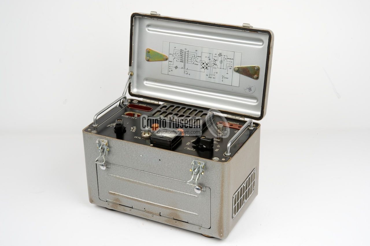
The circuit diagram of the standard PSU isn't particularly 'rocket science'
and doesn't provide any kind of voltage stabilization like the more advanced
TEMPEST PSU does. The full circuit diagram is given below. It is
also printed inside the top lid
of the later version of the standard PSU. At the left is the AC input voltage
selector that allows one of seven different taps of the primary side of the
transformer to be selected. With the later variant this selector
is also used as the ON/OFF switch.
The secundary side of the transformer has 7 different taps, allowing the
secundary voltage to be adjusted somewhat, to cope with small variations
in the mains power as well as variations in load. After rectification with
D1-D4, the DC voltage is stabilized with an array of capacitors (C2-C5).
|
The standard PSU has three sockets which are all located at the control
panel at the top of the device, below the hinged top lid. Below is a
specification of the pin-out of these sockets. The pinning of the sockets
is given when looking into the sockets from the top of the device.
The 3-pin socket is for connection of the mains AC voltage. It is located
at the top left of the control panel and accepts
the mains AC cable.
The 2-pin socket, just below it, is for connection of an external 24V DC source,
such as the battery of a (military) vehicle.
It accepts the 24V DC input cable.
Ensure that the correct polarization is used by checking the (+) and (-)
markings.
The 3-hole socket is for connection of the cipher machine. It is located
at the top right of the control panel and accepts
the 24V DC output cable.
Ensure that the correct polarization is used.
Also note that the pins of the mains socket and the 24V DC output socket
are not evenly spaced, in order to prevent them from being inserted the
wrong way around. Also note that the plugs of both cables (AC mains
and 24V DC) mate with each other. DO NOT TRY THIS.
|
At the heart of the frame is a large transformer that has several primary
and secundary taps that are routed to the two
bakelite rotary selectors
at the control panel. At either side are two of the four
rectifier diodes,
mounted in metal frames in order to obtain sufficient cooling.
The wiring is nicely bundled, but there is no
separation between primary and secundary wiring.
The image on the right shows the early model of the standard PSU.
In this version the stabilisation capacitors (C2-C5) are missing,
resulting in a less stable 24V DC output than the later version.
|
|
|
The device is constructed in such a way that the air can easily
flow through the case, using the grids at the sides of the case
as inlets. The large black grid
at the center of the control panel
acts as the air outlet. In normal use, the transformer should not
get too hot, but in areas where the mains voltage exceeds the
maximum rating of the device, the transformer could run hot.
|
|
AC
|
|
Alternating Current
|
|
DC
|
|
Direct Current
|
|
PSU
|
|
Power Supply Unit
|
|
|
|
Any links shown in red are currently unavailable.
If you like the information on this website, why not make a donation?
© Crypto Museum. Created: Monday 12 May 2014. Last changed: Friday, 20 December 2024 - 08:08 CET.
|
 |

|
|
|