|
|
|
|
|

|
|
USSR Fialka TEMPEST BP-25 →
TEMPEST power supply unit for M-125 (Fialka)
BPK-125 (Russian: БПК-125), is a power supply unit (PSU),
developed in the mid-1960s in the USSR especially for use with the
M-125 (Fialka) cipher machine.
It supercedes the standard BP-24 PSU,
and offers counter measures agains the exploitation of unwanted
emanations, known in the Western world as TEMPEST.
In Russian, this phenomenon is known as PEMIN (ПЭМИН) 1 [1].
|
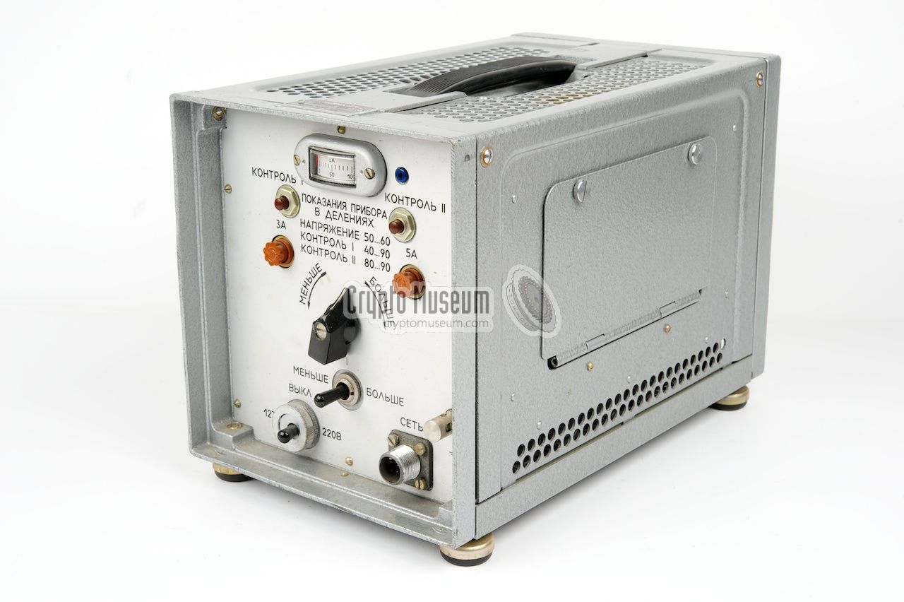
The device is housed in a grey hammer paint metal enclosure
that measures 280 × 200 × 170 mm and weighs 7.6 kg. When stowed,
the front and rear panels are
covered with a blank metal panel.
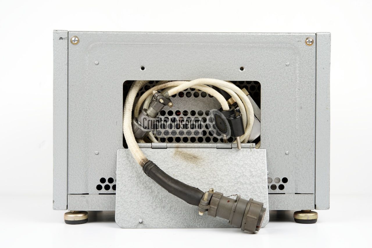
At the right side is a hinged compartment in which the
three mandatory cables are stowed.
The most important reason for choosing this PSU over the
standard BP-24 is its TEMPEST feature. It prevents
data from leaking out via the power lines. This is done in two ways:
(1) by using five switchable dummy loads (one for each data bit)
and (2) injecting noise into the 24V power line.
|
|
|
|
The device is suitable for all Fialka models (M-125, M-125M and M-125-3M).
It replaces the less secure standard BP-24, but was not
released in all countries.
As far as we know, the BPK-125 was only issued in the USSR
(Russia) and Poland.
In the other countries, the BP-24 remained in use.
|
-
ПЭМИН (PEMIN) is the abbreviation of
ПОБОЧНЫЕ
ЭЛЕКТРОМАГНИТНЫЕ
ИЗЛУЧЕНИЯ
и НАВОДКИ,
which means: Unwanted Electromagnetic Radiation and Interference.
|
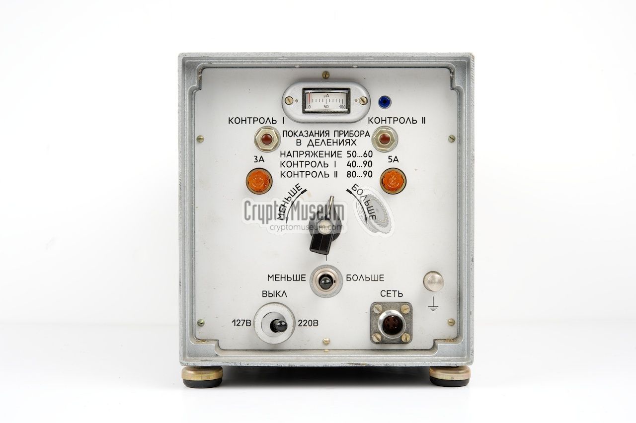
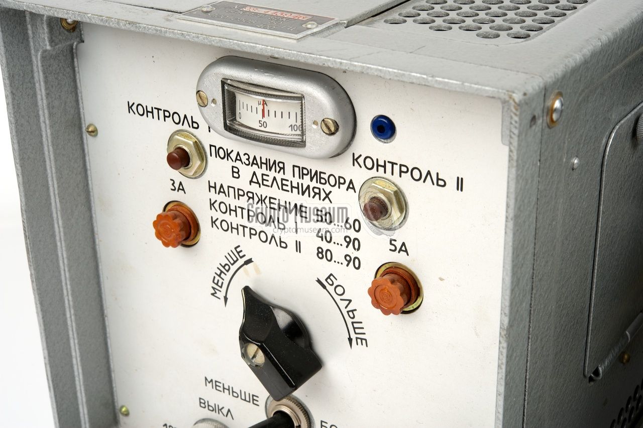
All controls of the BPK-125 are at the front panel. The switch at
the bottom left is used for selecting the correct mains voltage range
and for switching the device on and off. A ring with an
excentric disc protect this switch against setting it to the wrong
voltage (more about this below).
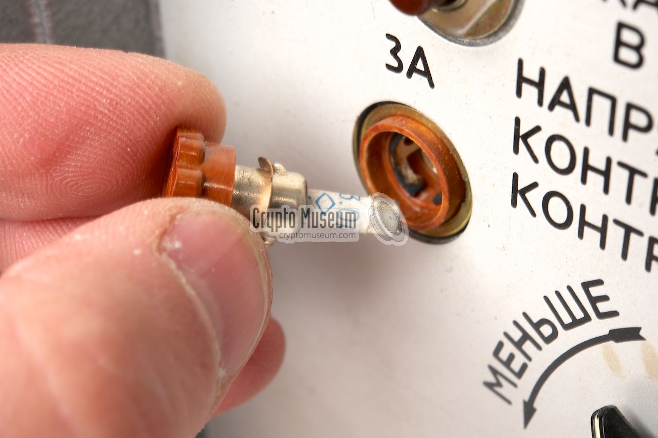
Above the mains voltage selector is a 3-position primary voltage
adjustment and - above that - the 10-position secondary voltage selector.
Above this selector are the primary (3A) and secondary (5A) fuses.
These are typical Russian fuses that may be a bit hard to obtain.
The section at the top is for checking the functions of the PSU.
When the PSU is in use, the meter at the top center should read
between 50 and 60. This indicates a nominal output voltage of 24V DC.
The two КОНТРОЛЬ buttons are used for checking the currents and
the TEMPEST feature.
The STROBE light, to the right of the meter, is also for checking
the TEMPEST feature (more below).
|
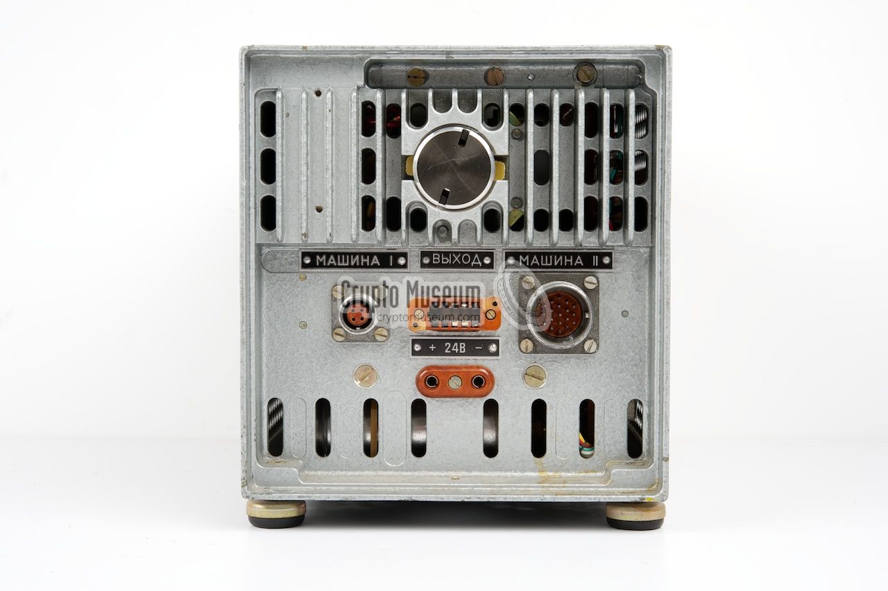
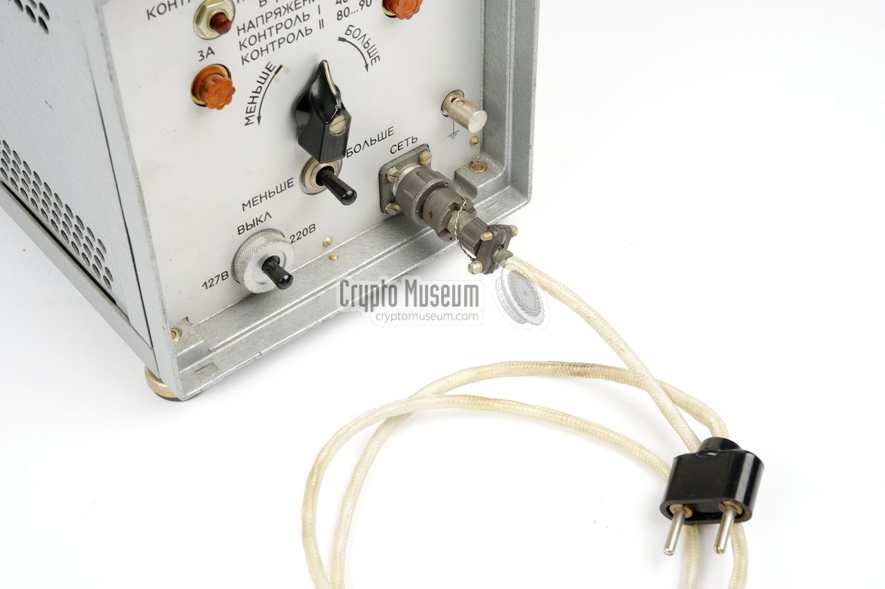
The receptacle for connection to the mains is at the front right
of the PSU. All other connections are at the rear, where four
further receptacles are present. The leftmost one (marked МАШИНА I) is the
24V output for Fialka.
The rightmost one (marked МАШИНА II) is for connection to
Fialka's data output.
If Fialka is normally connected to a transmitter or telegraphy device,
that device should now be connected to the center socket at the rear of
the PSU marked ВЫХОД (output).
Although it may seem unnecessary, the data socket
(marked МАШИНА II) must be connected, as otherwise
the machine will not work. This is done to ensure the use
of the TEMPEST feature.
An extra 24V DC output socket is available at the bottom.
This 2-pin socket can be used for connection of an extra device,
such as a work light.
The pinout of the connectors is described below.
|
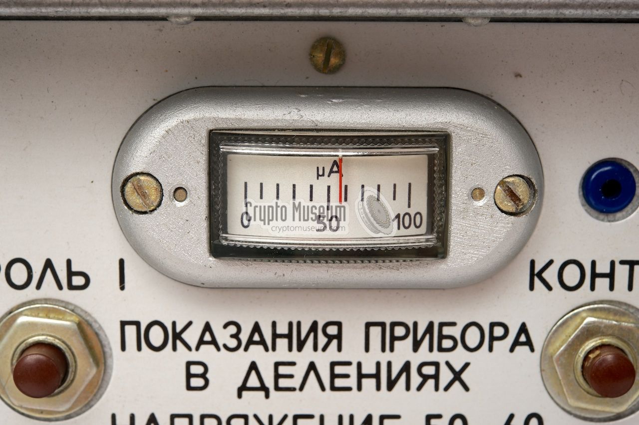
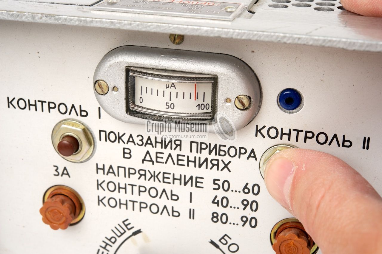
At the front panel of the BPK-125 are two indicators that can be used
to ensure correct operation of the device: a meter with a range from 0 to 100,
and a small indicator lamp to its right. Below these indicators are two
push-buttons marked КОНТРОЛЬ I and КОНТРОЛЬ II, as shown here:
The table below shows the effect of pressing one of the push-buttons.
When no button is pressed, the meter measures the raw 24V supply for which
the reading should be between 50 and 60. If it is outside this range, the
voltage selectors should be adjusted appropriately. In this situation,
the small indicator lamp will be off. For the following measurements,
Fialka must be powered and running.
While button I is pressed, the meter shows the level
of the injected noise (TEMPEST measure). Any reading between
40 and 90 is fine. While button II is pressed, the meter shows the voltage of
the internal 18V supply that feeds the noise generator.
It should be 80-90. If either measurement is out of range, the
TEMPEST feature
isn't working properly and requires repair.
|
| Button | Meter | Reading | Lamp |
|
|
| No button | 24V supply | 50-60 | Off |
| КОНТРОЛЬ I | Noise level | 40-90 1 | Flashes at strobe + valid data |
| КОНТРОЛЬ II | 18V supply | 80-90 1 | Flashes at strobe |
|
The lamp is used for checking the 5-bit data input. These are the lines
from Fialka that are used by the BPK-125 to simulate solenoid activity
(another TEMPEST measure). While button I is pressed, the lamp
flashes when the strobe signal is active and at least one solenoid
simulation circuit is activated.
When all solenoids are fired (character Ю (11111)) the lamp stays off.
While button II is pressed, the lamp flashes when the strobe signal is
active, regardless the state of the data bits.
➤ More about the TEMPEST measures
|
|
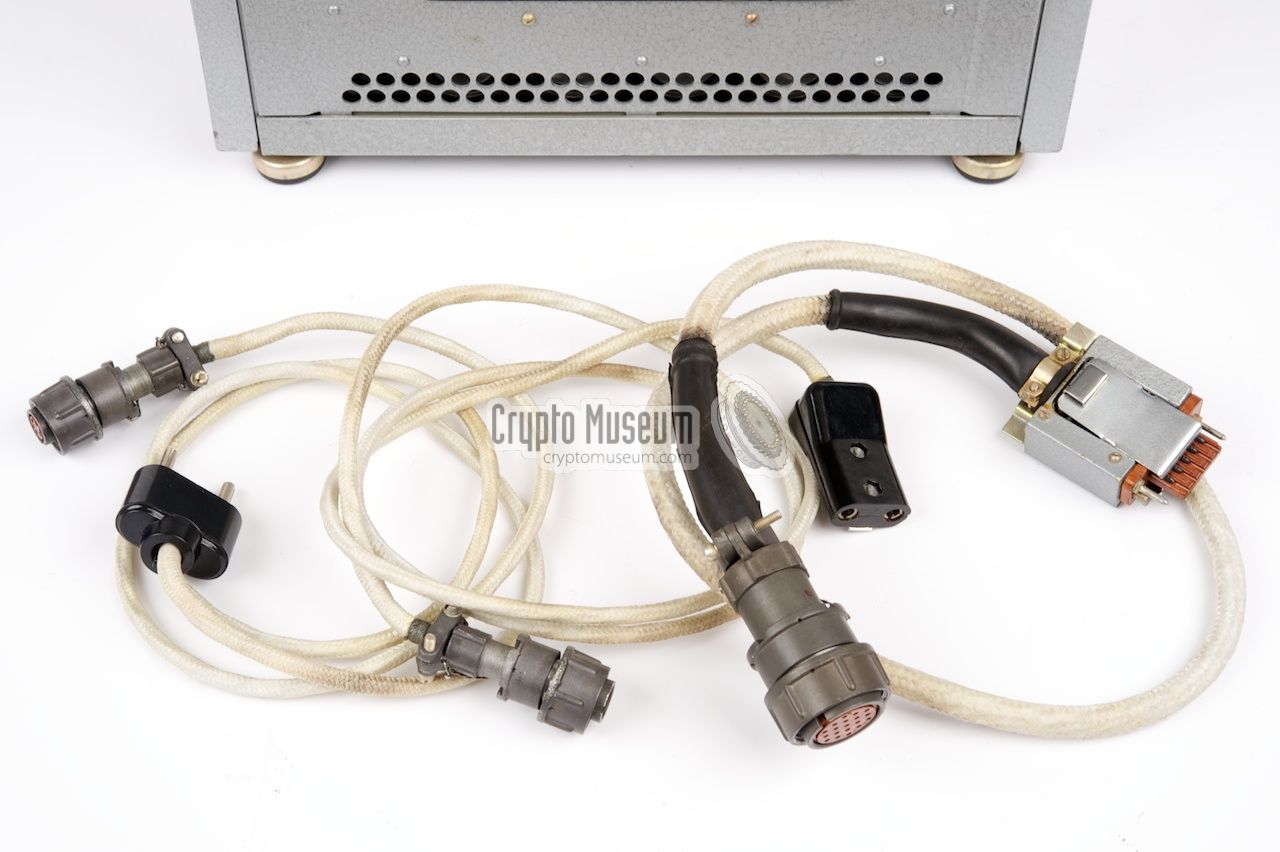
To use the BPK-125 PSU in combination with the M-125 (Fialka),
three cables are needed: (1) a mains power cable, (2) a 24V DC
cable for feeding Fialka, and (3) an interconnection data cable.
These cables can be stowed inside the
cable storage compartment
at the right side of the device.
|
The hinged lid to the cable compartment
is held in place by two screws that can be
loosened by hand or,
if they are really tight, with the aid of a
screwdriver. If the cables are present, it may be a bit difficult
at first to get them out of the storage compartment as they
may have become stiff.
Be carefull with these cables as they might have become fragile
after all this time. Once you got them out of the storage compartment,
it is probably best to leave them out and store them separately from
the PSU from now on. This will protect the cables against too much
bending.
|
|
|
For safety reasons, it is advised to thoroughly check the
mains power cable
before connecting it to the mains. As the cable is rather old,
the insulation of the internal wires may have become brittle and might have to
be replaced. Use the mains cable only if you are certain that it is safe.
|
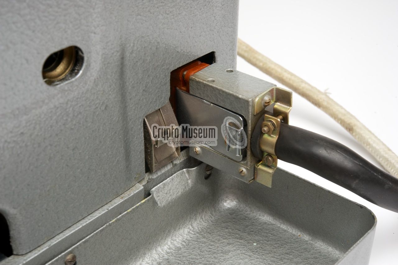
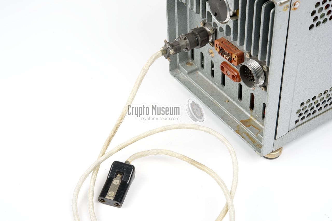
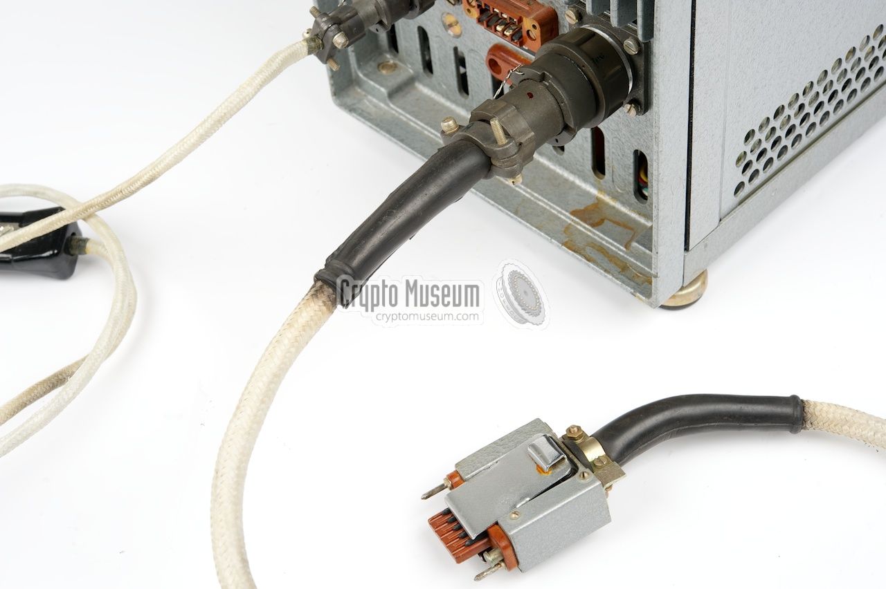
The data cable
is something truely special. It is a vital part of the
TEMPEST feature of this PSU and allows the PSU to monitor the 5-bit data
stream generated by the Fialka. One side of this cable holds a
10-way data connector
that fits the digital data output
at the right side of the Fialka.
A switch, that is mounted at the base of this plug, senses whether the
plug is placed in the socket and activates a relay inside the PSU.
This relay turns the 24V output of the PSU on. This is done
to ensure that the cable is in place and that the mandatory TEMPEST
measures are used.
|
|
|
At the other end of the data cable is a rather
large circular plug
that should be connected to the MACHINA II (МАШИНА II) socket at the rear of
the PSU. If this cable is missing, it is advised to build a
suitable alternative before continuing.
The remaining cable simply connects the 24V DC output
of the PSU to the 24V DC input at the left side of
the Fialka.
|
|
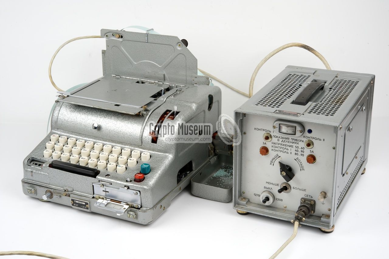
The power supply unit (PSU) can be placed either to the left
or to the right of the Fialka.
It can also be placed behind the machine or on a shelf.
The various cables should just be long enough for that.
Before connecting the PSU to the Fialka, you first
need to check the voltage settings on the device, and adjust them if
necessary. First check the setting of the ВЫКЛ switch at the bottom
left of the front panel and ensure that it matches your mains AC voltage:
either 127V or 220V.
|
This switch can be altered by unscrewing the ring
and rotating the excentric disc
at the center by 180°. The centre setting
of this switch turns the PSU off. For most European 230V networks,
you should set this switch to 220V.
If your mains voltage is slightly lower or higher, you may compensate for
this by setting the toggle switch at the center to МЕНЬШЕ (less)
or ВОЛЬЕ (more).
For 230V networks, which are common in Europe nowadays,
this switch should be set to МЕНЬШЕ (less - i.e. the leftmost setting).
It prevents the mains transformer from saturating (running hot).
|
|
|
Ensure that the PSU is switched OFF
(ВЫКЛ set to the centre)
and connect the Fialka to the two sockets at the rear of the PSU.
A thin cable connects the PSU socket МАШИНА I
to the 24V DC input at the left side of the Fialka.
A thick cable connects PSU socket
МАШИНА II to the data output
at the right side of the Fialka.
Ensure that the Fialka itself is switched off at this stage.
Now connect the PSU to the mains
by supplying the mains AC voltage to the СЕТЬ socket at the front
right and then turn the PSU on (leave Fialka off at this stage).
Ensure that the meter at the top
shows a reading between 50 and 60.
If it is higher or
lower, use the rotary switch at the centre to adjust the voltage.
When it is within the required range, it is safe to turn the Fialka on.
At this stage, the motor of the Fialka should start running.
If it doesn't, there might be a problem such as a binding motor
(grease dried up) or a blown fuse,
either of the PSU or of the Fialka.
|
|
The BPK-125 is protected against data leakage via the power lines,
also known as side-channel leakage. This is known as the TEMPEST feature.
In Russian it is known as PEMIN (ПЕМИН).
It consists of two countermeasures:
|
- Ballast compensation
Data (text) is processed by the Fialka cipher machine in
5-bit digital form. When printing text onto paper and/or punching characters
into a paper tape, the digital data drives 5 solenoids. These solenoids control
the stop-position of the print head, and determine which holes will be punched
in the paper tape. Depending on the output character, between 1 and 5 solenoids
are fired, resulting in a variable current consumption that can be traced back
to the mains power line. A potential eavesdropper could use these variations
(in combination with other compromising emanations) to reconstruct the plaintext.
This problem is solved by replacing the inactive solenoids by a series
of dummy loads, also known as artificial loads.
Each dummy load has exactly the same resistance as a solenoid,
and therefore draws the same amount of current when it is activated.
For example when the SPACE-character is printed (10001) only two
solenoids are fired. The BPK-125 will then activate three dummy loads (01110)
to ensure that the total current drawn by the system remains the same as if
the Ю-character was printed (11111).
- Noise injection
Although the above should theoretically be sufficient to ensure a constant
current consumption, data might still leak out as a result of 'glitches' on
the power lines. These glitches, also known as switching transients,
occur when switching solenoids on and off. Although these gliches
are usually very short, they can still be detected on power lines, up to
several hundreds of meters from the source.
Instead of filtering the glitches, the designers of the BPK-125 have choosen
to mask them by injecting noise into the power line. Due to the random nature
of noise, it is generally impossible to determine which pulse is a glitch and
which is part of the injected noise.
|
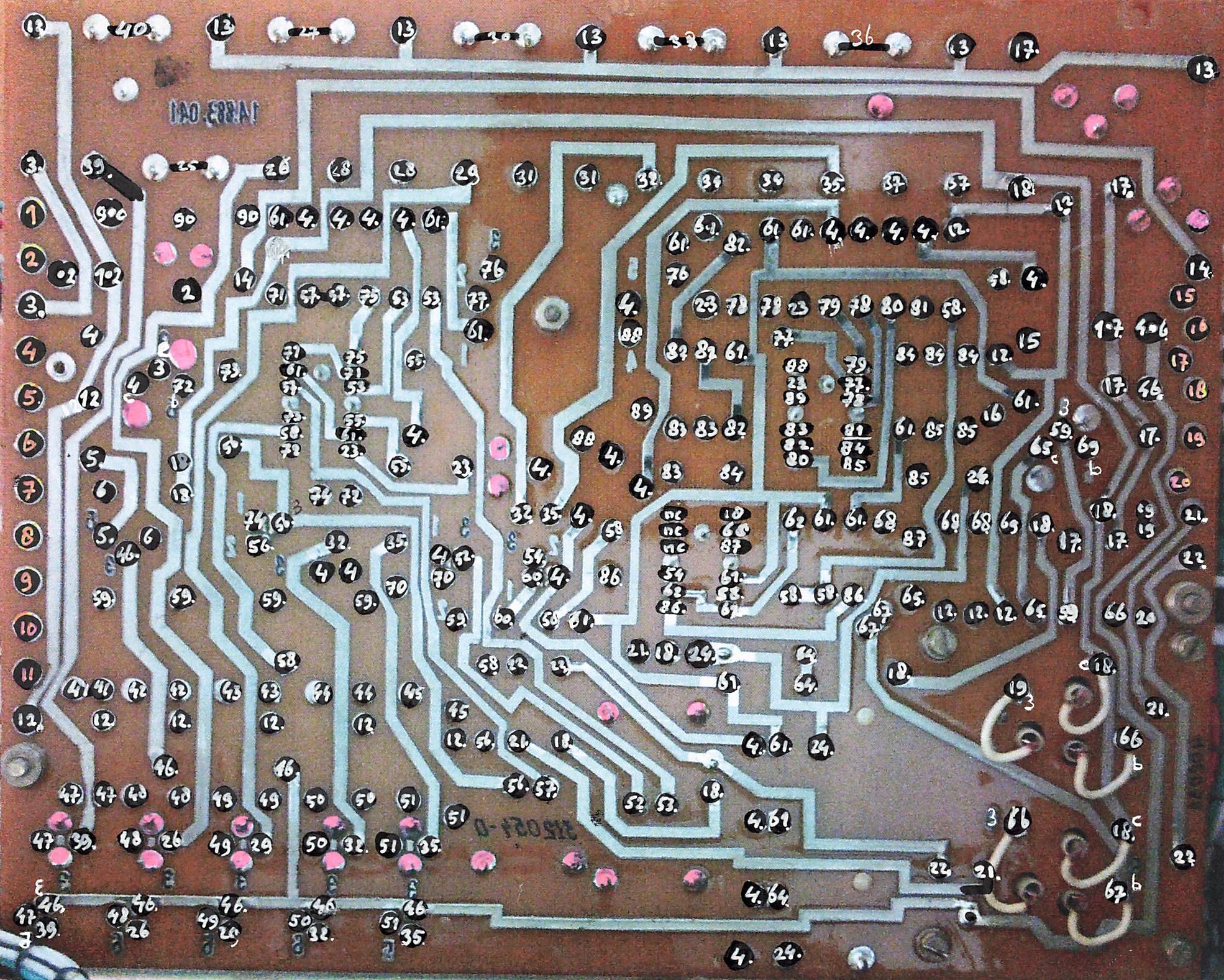
Although most electronic parts of the BPK-125 are located on a single
printed circuit board (PCB), the device is best described as a set of
modules. Note that the device has the +24V rail connected to ground,
rather than the more common 0V rail. This is not reflected in the
circuit diagrams below however. For clarity, the 0V rail is denoted by the
common ground symbol  , whilst the chassis is
represented by the earth symbol
, whilst the chassis is
represented by the earth symbol  .
Furthermore, the current flow is from left to right.
.
Furthermore, the current flow is from left to right.
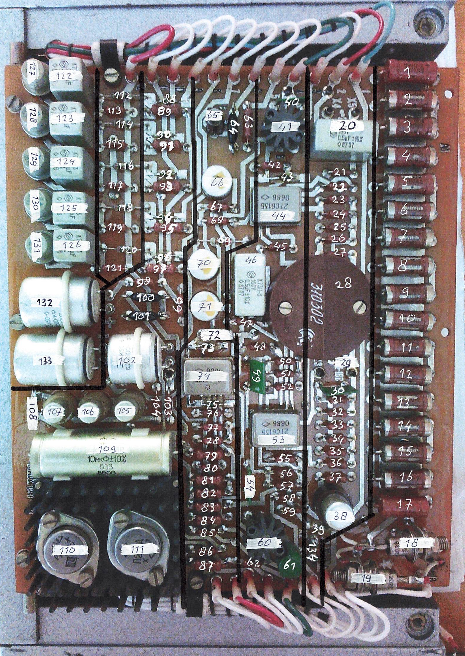
The text and circuit diagrams below are largely based on the work
of Bart Wessel [2]. As there is no circuit diagram of this device in
the public domain, he had to trace each and every track of the PCB
and follow each single wire, which is by no means trivial. As part of
his research, he numbered all components at the
upper side of the PCB.
In the circuit diagrams below, these numbers are prefixed with a hash
symbol (e.g. #123). In addition, he numbered all contact points at
the bottom of the PCB.
In the circuit diagrams below, these numbers
are shown in red (e.g. 18).
Note that both types of number are only visible when
placing the mouse pointer over the diagram.
➤ Component index (top side of PCB)
➤ Contact index (bottom side of PCB) 1
|
 |
-
Note that the image of the bottom side of the PCB
is mirrored. This means that the tracks are shown as if they were viewed from
the top of the PCB. This was done to make tracing of the PCB
easier [2].
|
Below is a simplified circuit diagram of the BPK-125 power supply unit.
At the left is the AC mains power inlet. At the right are the connections
to the M-125 (Fialka) cipher machine (МАШИНА I and МАШИНА II).
As the circuit of the device is
rather complex, we have divided it into six functional blocks that are
further described below:
(1) 24V DC power supply,
(2) ballast compensation circuit,
(3) meter circuit,
(4) regulated 18V supply,
(5) noise generator and
(6) relay control circuit.
Note the switch (S6) at the far right that is part of the interconnection
cable. It must be closed before the device can be used. This is done by
inserting the 10-pin plug of the interconnection cable into socket Ш4
at the right side of the M-125 (Fialka). Also note the
difference between Ground (chassis) and the 0V rail. The latter
represents the (-) side of the +24V power supply.
In addition to this, there is a switched 0V rail (via Fialka) that is indicated
by the  symbol.
➤ Download the block diagram as PDF
|
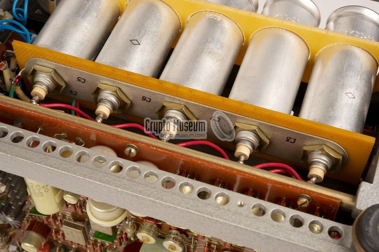
Below is the circuit diagram of the basic 24V power supply, which is of
straightforward design. A conventional transformer converts the mains AC
voltage into a much lower voltage, which is rectified in a bridge rectifier
composed of four discrete diodes (V1-V4). The resulting voltage of approx.
24V DC is then smoothened by five 2000µF electrolytic capacitors (C4-C8).
There are two fuses: a 3A one in the primary circuit and a
5A one in the 0V rail of the secondary circuit.
The output voltage is adjusted by means of three manually operated switches:
(1) A safeguarded switch (S1) that should be set to match the local AC mains
voltage of either 127 or 220V AC. Note that this switch also acts as the
master on/off switch.
(2) A 3-position switch (S2) in the primary circuit for normal, less (МЕНЬШЕ)
or more (БОЛЬШЕ) voltage (course).
(3) An 8-position rotary switch (S3) to select a secondary tap of the transformer
(TR1). This is the fine adjustment.
|
A meter (at the top of the front panel) indicates the secondary voltage
and should be used to choose the correct settings for the above switches.
The meter circuit is described separately.
➤ Download the 24V supply as PDF
|
|
|
Ballast compensation
TEMPEST measure 1
|
|
|
Below is the circuit diagram of the ballast compensation circuit. The Fialka
data cable provides the BPK-125 with five data signals (positive pulses)
and a strobe signal (negative pulse). For each of the five solenoids – used
in Fialka to punch holes in the paper tape – the ballast circuit
has a corresponding transistor with an artificial load that draws an
equivalent current. When a solenoid in the Fialka is not fired for a
particular character, the corresponding transistor in the BPK-125 activates
the artificial load instead. This way, each punched character draws the same
current.
Note that in order to simplify the circuit diagram, we have only shown
the ballast circuit for one of the data bits. This is the area marked
in purple. This circuit is replicated for each of the other bits, as
indicated with purple stars  .
The transistors at the bottom handle the strobe signal.
At the far right are two push buttons and a signal lamp. These are part
of the meter circuit and allow checking of the strobe
pulses in combination with data pulses (
.
The transistors at the bottom handle the strobe signal.
At the far right are two push buttons and a signal lamp. These are part
of the meter circuit and allow checking of the strobe
pulses in combination with data pulses (KI ), or just strobe pulses (KII ).
The simplified circuit diagram above shows how a single data bit is
processed. To the left of the dashed line is the Fialka output circuit.
Whenever a data bit is active the base of transistor T1 is driven low
(negative logic) and T1 conducts. As a result, the solenoid is activated.
This signal (positive pulse) is then fed to the BPK-125, where it
drives the base of T2 high. As a result, the artificial load is not
activated. Likewise, when the solenoid is not driven, the signal at
the base of T2 is low, as a result of which it conducts and the artificial
load is activated. The strobe circuit around T3 and T4, ensures that
the artificial load can only be activated when a (negative) strobe pulse
is present at the same time (details of the strobe circuit have
been omitted for clarity).
➤ Download the ballast compensation circuit as PDF
|
|
|
Noise generator
TEMPEST measure 2
|
|
|
Below is the circuit diagram of the noise generator.
This elaborate circuit generates noise that is injected into the raw
24V rail, by means of a power transistor (V5) that draws between 0.5
and 1A from the same 24V rail. This is done to mask any residual
fluctuation in the actual current drawn by Fialka, as
far as this is not handled by the
ballast compensation circuit.
The circuit is powered by a
regulated +18V supply (above),
so that the noise generator is not affected by its own noise.
Note that the 0V rail is switched via the on/off switch of
Fialka, as indicated by the
symbol.
The actual noise circuit consists of two parts: (1) a noise generator
and (2) a noise injector. The noise generator is shown above. It
comprises a noisy diode (#108) of which the signal is amplified
in two high-gain amplifiers, filtered (TR2), further amplified,
clipped and then buffered. The noise level can be adjusted with
potentiometer (#70). The output is available at the right (57).
The noise from pin (57) is then fed to the noise injection circuit
shown above. The final stage of this circuit consists of a power
transistor (V5) plus two resistors (R1, R2) that are mounted on a heatsink
at the rear of the BPK-125.
It draws between 0.5 and 1 from the main 24V supply.
The noise is injected into the 24V rail via R1.
The same signal is fed to the meter circuit via pin (2).
➤ Download the noise generator as PDF
➤ Download the noise injector as PDF
|
Note that, when Fialka is running, the injected noise can be heard
through the motor, as if there is sand in the mechanism. This is
perfectly normal and is an indication of correct operation of the
noise masking feature. When the same Fialka is connected to the earlier
BP-24 PSU, or when the noise generator of the BPK-125
is misaligned or broken, the motor appears to be running more smoothly.
Below is the circuit diagram of the meter circuit. It is used to
verify the correct operation of the BPK-125 and its TEMPEST features.
By default, the meter shows the raw secondary voltage (24V).
Two push buttons (КОНТРОЛЬ I
and КОНТРОЛЬ II) allow measuring of the internal
18V regulated power supply
(КОНТРОЛЬ II), and the noise level generated by
the noise generator (КОНТРОЛЬ I).
If one of these readings is not as indicated on the front panel,
the noise generator is misaligned or broken.
Note that a valid noise measurement is only possible when Fialka is running.
The circuit to the right of the dashed line is the actual meter circuit.
The small lamp (La) is located to the right of the meter on the
front panel of the BPK-125. When КОНТРОЛЬ I is depressed, it
flashes when the strobe signal and one or more data bits are fired.
No data means no flash.
When КОНТРОЛЬ II is depressed, it flashes on each strobe signal,
regardless of the presence of any data bits.
The lower part of the circuit (S4a, S5a and La) are also shown in the
circuit diagram of the ballast compensation circuit.
➤ Download the meter circuit as PDF
|
Below is the circuit diagram of the relay control circuit.
The relay is activated as soon as the BPK-125 is powered up.
This disconnects the 0V rail from the power output socket (МАШИНА I),
so that the connected M-125 (Fialka) doesn't run.
Only if the the dedicated interconnection cable is used to connect
the BPK-125 to the Fialka (МАШИНА II),
switch S6 (part of the cable) 1 will be closed.
As a result, the relay is released and power will be
applied to connector МАШИНА I.
Note that the above circuit diagram shows part of the
ballast circuit (left). This is done to show how the
relay is powered. The actual relay circuit is at the right,
around transistor #65 (2T208M). To allow the relatively high current
drawn by the Fialka, both contacts are used in parallel. The relay
is mounted to the rear panel, behind the mains transformer, aside the
power transistor.
➤ Download the relay control circuit as PDF
|
|
-
The interconnection cable employs a small switch (S6) to detect that
it has been plugged into the Fialka.
|
|
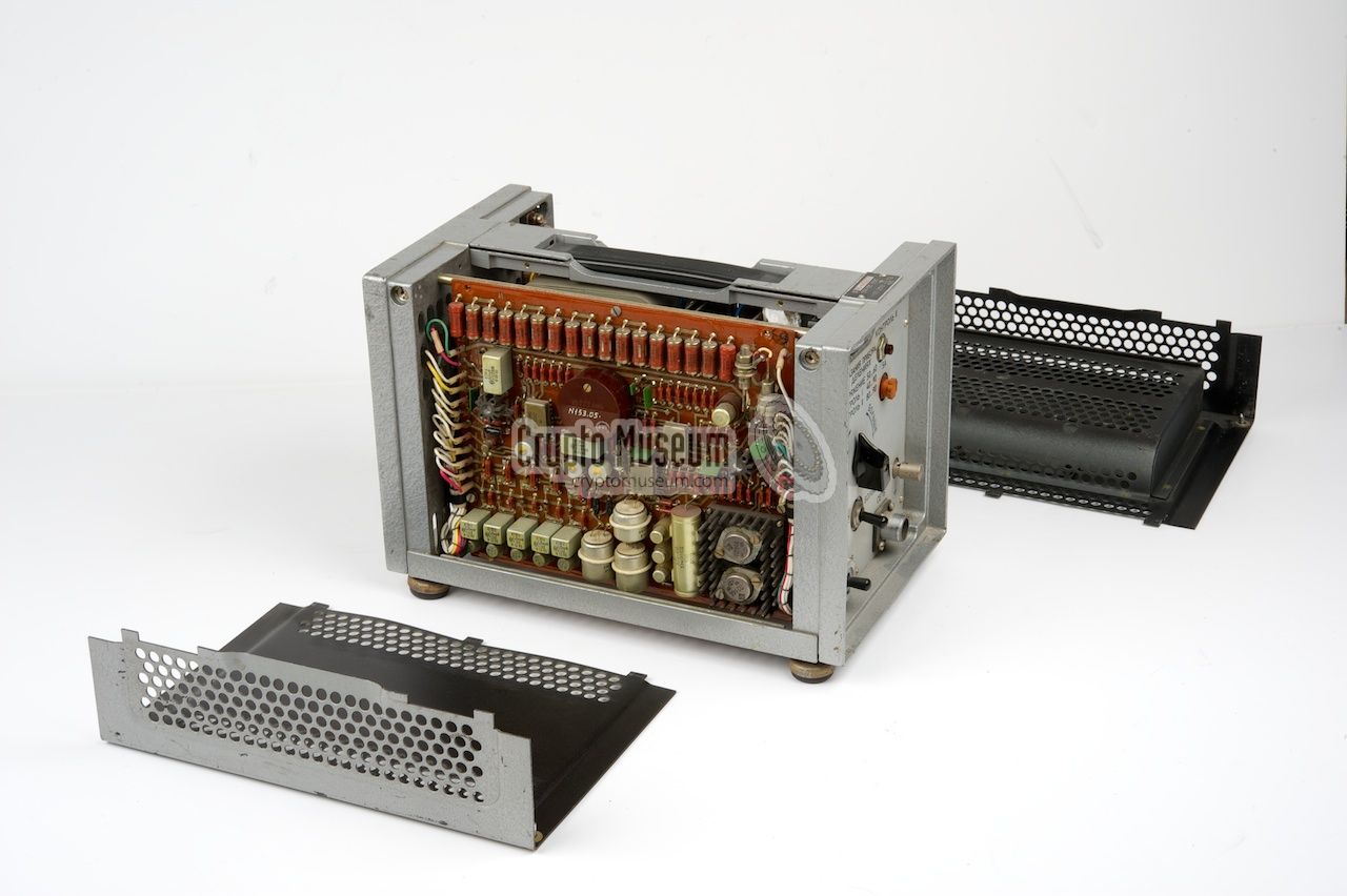
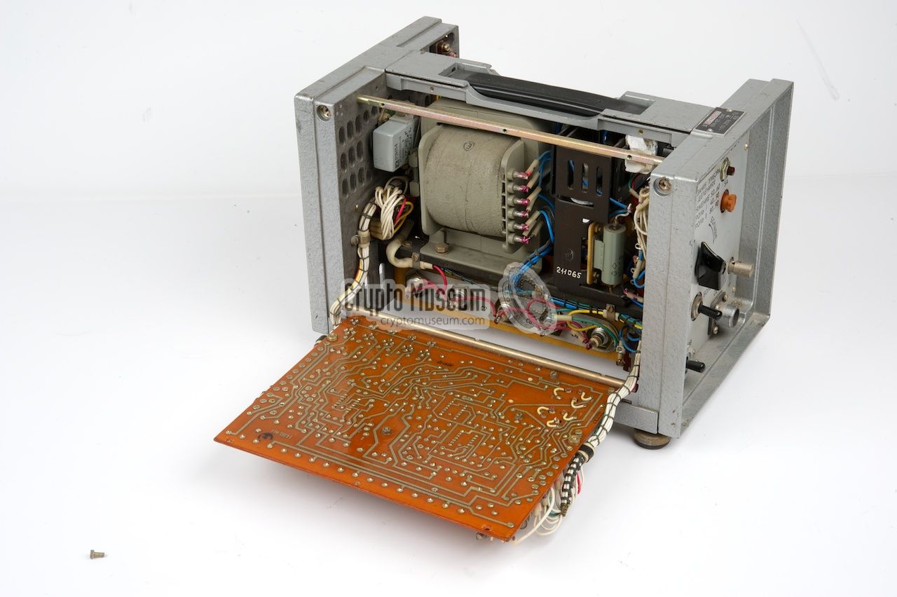
The interior of the BPK-125 can be accessed by removing the two side panels
and the bottom panel. The side panels are held in place by two screws
at either side. After
removing the two screws, the side panel
can be removed. The other side panel can
be removed in the same way.
|
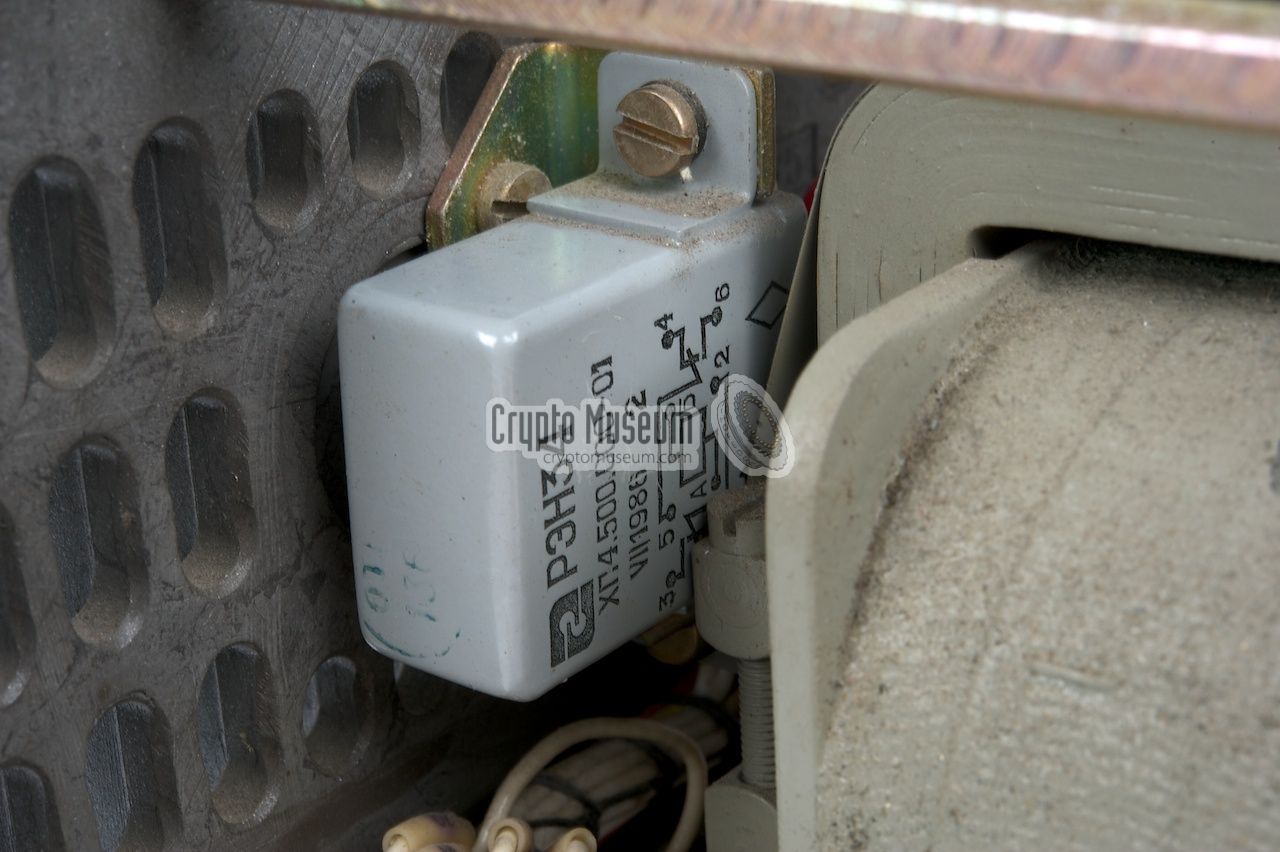
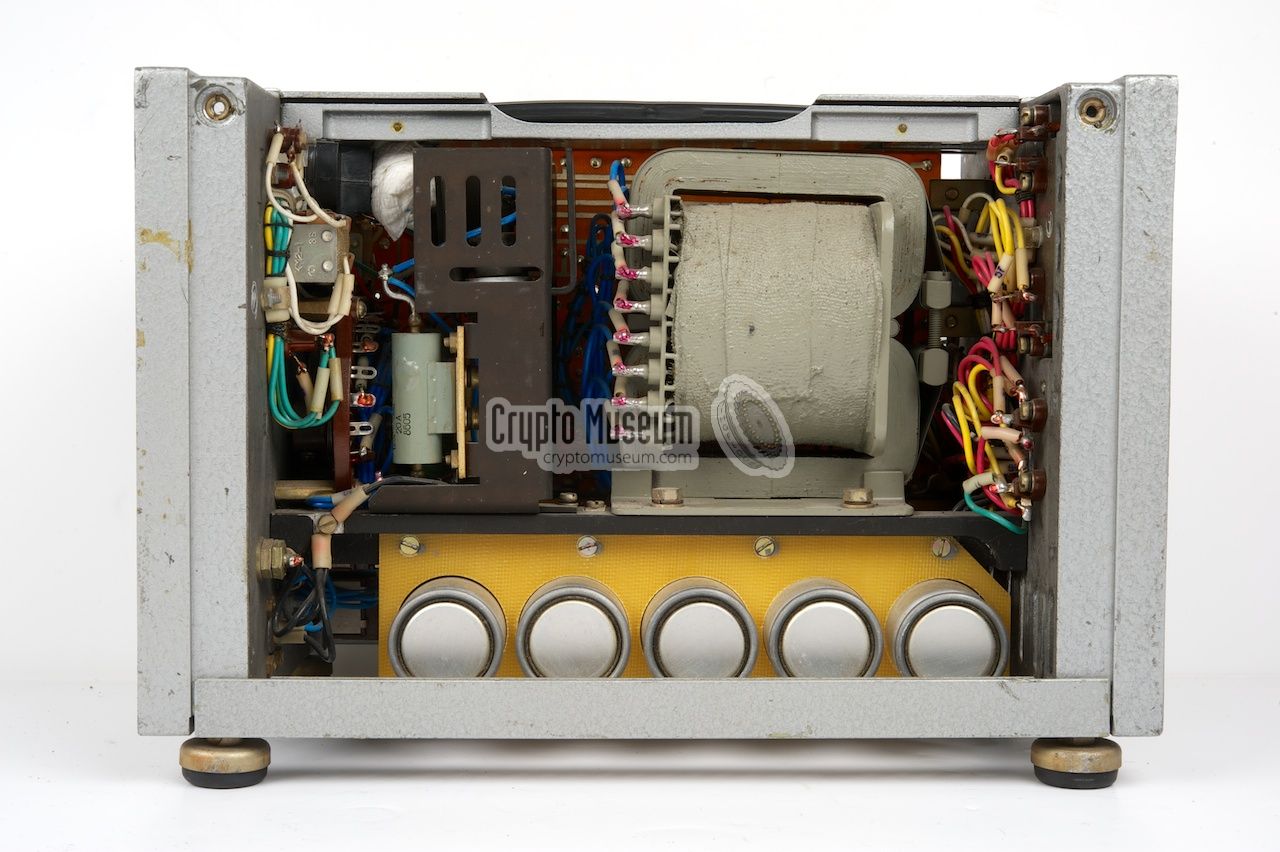
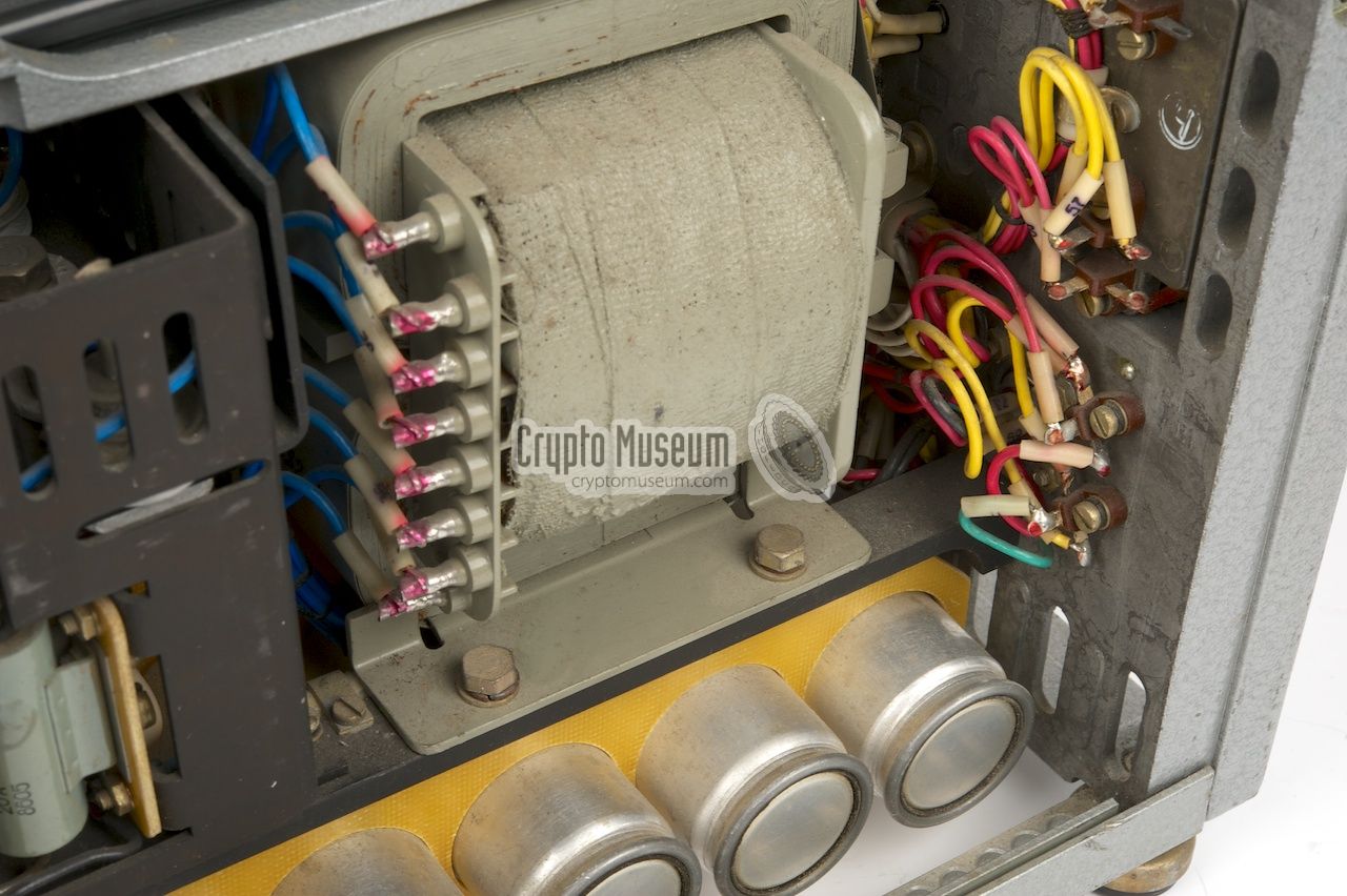
At the right side,
the grey mains transformer is immediately
visible. Below the transformer is an array of five capacitors
that are connected in parallel. Some of the power transistors are
mounted to the rear panel for sufficient cooling.
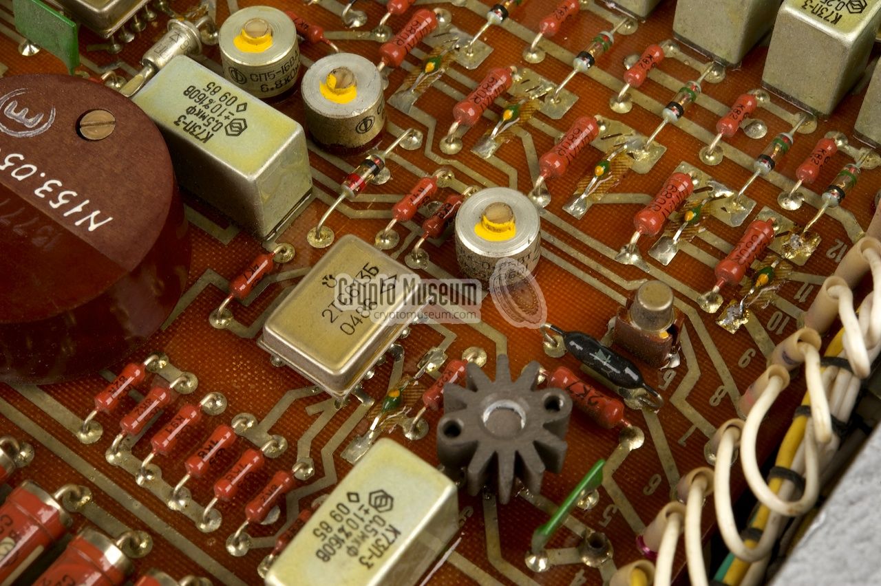
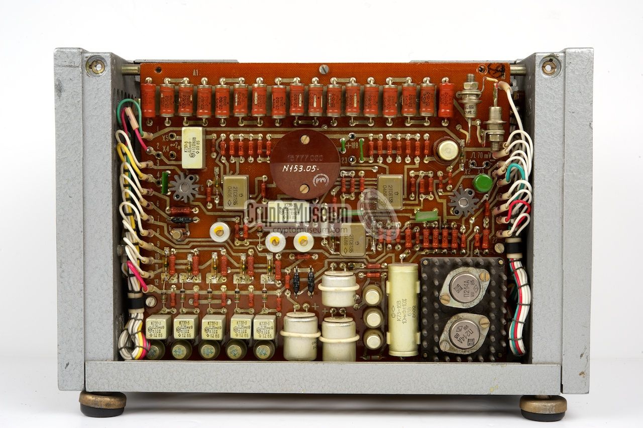
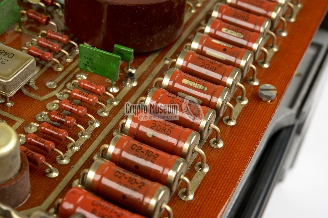
The other side holds a large brown pertinax 1 printed
circuit board (PCB) with the electronic components. Apart from the 18V
regulator, this board contains the two TEMPEST circuits. The dummy-load
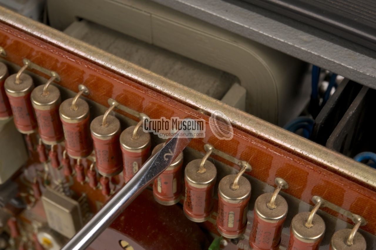
resistors are visible as an
array of resistors
at the top edge of the board. The actual
TEMPEST circuits
are scattered all over the PCB.
|
|
|
|
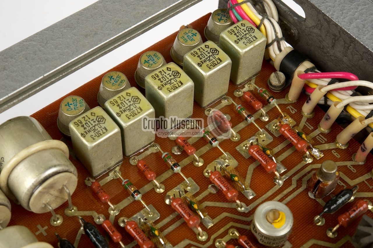
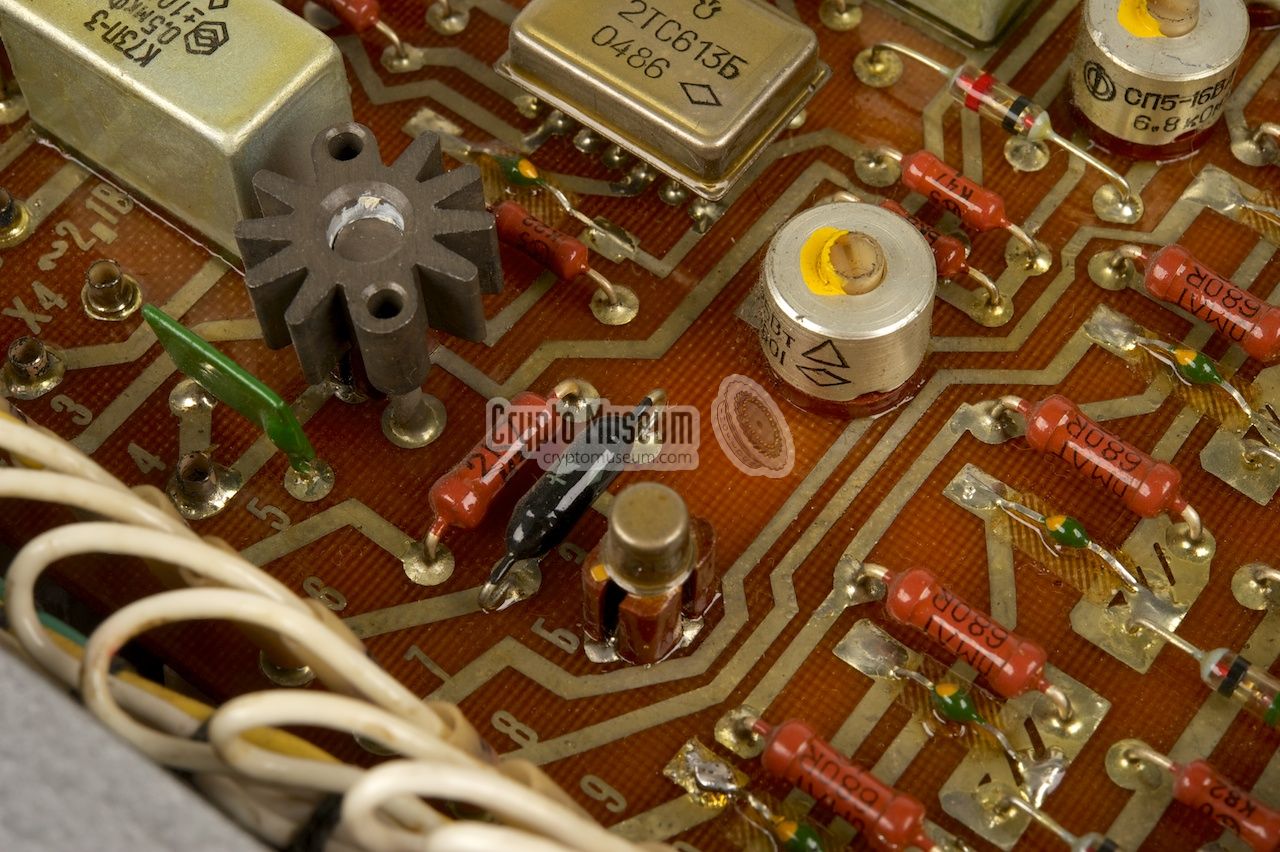
Also on this PCB is the
STROBE sensing circuit
that enables the TEMPEST circuit
whenever the user presses a key on the Fialka keyboard.
This circuit also drives the STROBE check light,
to the right of the meter a the front panel.
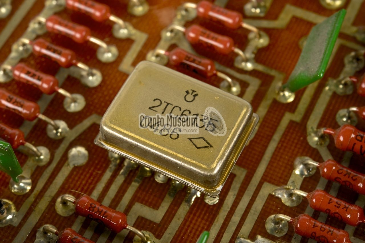
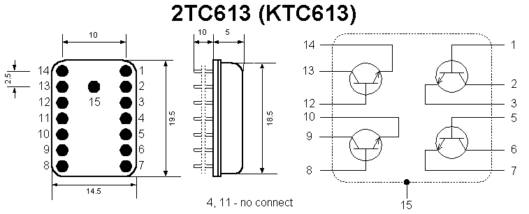
In some of the circuits, 2TC613 ICs are used [a].
Each of these ICs contains four transistors, They belong to
one of the first generations of Russian ICs.
Behind the transformer is a relay that switches the 24V output.
It is activated by the data connector switch.
|
|
At the bottom right of the front panel is a 4-pin male connector
to which the mains AC network (110 or 220V) should be connected. Below
is the pinout when looking into the receptacle.
|
- Mains AC (1)
- Mains AC (2)
- GND
- not connected
|
|
|
An important feature of the BPK-125 is the ability to
suppress data leakage via the power line (TEMPEST). For this, it is
necessary to connect the data output of the M-125 Fialka (Ш4) to
the data input of the BPK-125. This is the circular 19 pin connector
(plug) marked MACHINA II (МАШИНА II) at the rear of the device.
Below is the pinout when looking into the connector.
|
- Data 1
- Data 2
- Data 3
- Data 4
- Data 5
- +24V in mode З (Cipher)
- unused
- 0V
- Strobe (pulse)
- +24V in mode О (Plain)
- not connected
- not connected
- not connected
- not connected
- not connected
- not connected
- not connected
- Switch (A)
- Switch (B)
|
|
For connection between the data output of the M-125 (Fialka)
and the BPK-125 power supply unit, a special cable is provided.
This cable can be stowed in the side compartment of the PSU.
One end of this cable has an (angular) circular 19-pin female
connector that should be fitted to МАШИНА II on the BPK-125.
The other end has a 10-pin data connector that should be connected
to socket Ш4 at the right side of the M-125.
Without this cable, the PSU cannot be used.
The diagram above shows how the data cable is wired. All pins
of the 10-pin data connector are wired to pin 1-10 of the
circular connector. A momentary switch, that is embedded in
the base of the 10-pin data connector, is wired to pins 18 and 19
of the circular connector. The switch will be closed when the
data connector is fully seated in the data output (Ш4) of
the M-125 (Fialka).
|
|
At the centre of the rear panel of the BPK-125 is a 10-pin socket
marked ВЫХОД,
on which the data output of the connected Fialka
is available. This socket is wired in parallel to the 19-pin
circular connector, and has the same pinout as the data output
socket (Ш4) on the Fialka.
It can be used for the connection of a transmission device,
such as the P-590A (П-590А) interface.
|
- Data 1 (s1)
- Data 2 (s2)
- Data 3 (s3)
- Data 4 (s4)
- Data 5 (s5)
- +24V in mode З (Cipher)
- not connected
- 0V
- Strobe (pulse)
- +24V in mode О (Plain)
|
|
- Klaus Kopacs
- Paul Reuvers
- Marc Simons
- Bart Wessel
|
|
|
|
Any links shown in red are currently unavailable.
If you like the information on this website, why not make a donation?
© Crypto Museum. Created: Monday 12 May 2014. Last changed: Wednesday, 05 November 2025 - 11:48 CET.
|
|

|
|
|
|


