|
|
|
|
|

|
|
← Nagra ← JBR
The Nagra JBR was a covert audio recorder
that was initially developed for
the FBI
and two other US Government agencies, but was later also used by
law enforcement in Canada and in the UK.
The JBR
was introduced in 1984 and became an instant success, but
as it was a recording-only device, a separate playback system was needed.
The system had to be able to accept Nagra's propietary tape cassette format
and, more importantly, it had to correct small variations in speed that
were caused by the fact that the JBR does not have a flywheel/capstan
mechanism.
|
|
|
Two years after the introduction of the JBR, during which time specially
adapted Nagra SN units were used as a gap-fill solution, the PS-1 playback
system was ready. It had a built-in Time Base Corrector (TBC)
with an adjustable analogue delay line that used the
5.461 kHz signal on the JBR's control track to eliminated the short-term
speed variations, also known as wow and flutter.
The result is an accurate, sophisticated, capstan-less,
and hence maintenance free, playback system
with a high audio playback quality, built to the well-known Swiss
manufacturing standards.
The PS-1 was introduced in 1986 and stayed in production for several years,
along with the JBR miniature recorder. In total 657 PS-1 units were built
(compared to 1118 JBR units) [2] for a unit price of CHF 16,000 (Swiss Francs,
approx. 25,600 US$ in 1986).
They were available only to law enforcement and intelligencies agencies
in the US, Canada and the UK, and were never listed in the Nagra catalogue.
For a long time they remained unknown to the public, mainly because the intelligence agencies forced Nagra to keep their existence secret
for many years.
The JBR and the PS-1 were the last electromechnical
devices from Nagra before digital recording took over.
|
Most of the controls of the Nagra PS-1 are at the top surface, which
consists of an eloxed aluminium panel, with a solid spring-suspended
sub-frame at the center. The sub-frame is milled out of a solid aluminium
block and contains all mechanical (i.e. moving) parts, such as the motor,
the tape guides and the tape tension arm. Furthermore it carries the
playback head.
The rest of the top panel contains the usual controls, such as volume,
balance (between the two channels) and equalizer. At the bottom centre
are four grey buttons that are used to control the tape (LOAD, STOP, START
and SPOOL). Furthermore, at the left centre is the expander adjustment
that compensates for the fact that the JBR compresses the dynamic range
during the recording.
The image above shows a close-up of the sub-frame that holds all mechanical
parts. The large tape roller
at the bottom left acts as a tape guide but also
has a built-in optical encoder that is used to measure the current tape speed.
It is used by the motor management system to guarantee a constant tape speed
during playback.
This is necessary because the PS-1 does not have a capstan with
flywheel and has the advantage that the PS-1 is nearly mantenance-free.
On top of that, the built-in Time Base Corrector (TBC)
uses the 5.461 kHz signal from the recorded control track to correct
any short-term speed variations, also known as wow and flutter.
|
At the bottom right is a panel with push-buttons
that is normally covered
by a spring-loaded panel. After lifting the flap, the buttons become visible.
The buttons can be used to set or reset the tape length counter, or to
jump to a certain section on the tape. After selecting the required function, the
numbered keys are used to enter a value. The tape counter is pretty accurate.
The PS-1 can be powered by various sources. For desktop use, it is best
powered from the AC mains.
A recessed switch at the rear panel allows selection
of the appropriate mains voltage.
|
|
|
When used in the field, the PS-1 can be powered by the internal batteries
(accessible via a panel in the bottom of the case),
or an external DC source between 11 and 20V. The knob at the top left of the
control panel is used to select the desired source, or disconnect the unit
completely.
Most of the connections of the PS-1 are located at the
rear panel, that also
holds the mains power switch and the fuses.
There are sockets for connection to the mains, an
external 11-20V DC power source, line in and outputs, a footwitch, a remote
control unit and an external TBC.
The two side panels each hold one of the speakers, whilst the
right side panel
also holds the socket for connection of the headphones, plus a small slide switch
to disable the speakers.
|
As the PS-1 is a playback-only device, the tapes have to be recorded on a
separate recording device. This is the
Junior Body Recorder (JBR)
that was release two years before the
PS-1, in 1984. It was designed to meet the tough specifications of the FBI
and was the smallest professional body-wearable recorder at the time.
Like with the PS-1, the existence of the JBR was kept secret for many years,
in order to give law enforcement and intelligence agencies an advantage over
criminals.
➤ More information
|
|
|
|
For the Nagra JBR and the PS-1, Nagra developed its own
proprietary tape cassette format
that is not used by anyone else. The specifications of the tape
itself are identical to that of the Nagra SN,
but the supply and pickup reels are integrated into a single unit
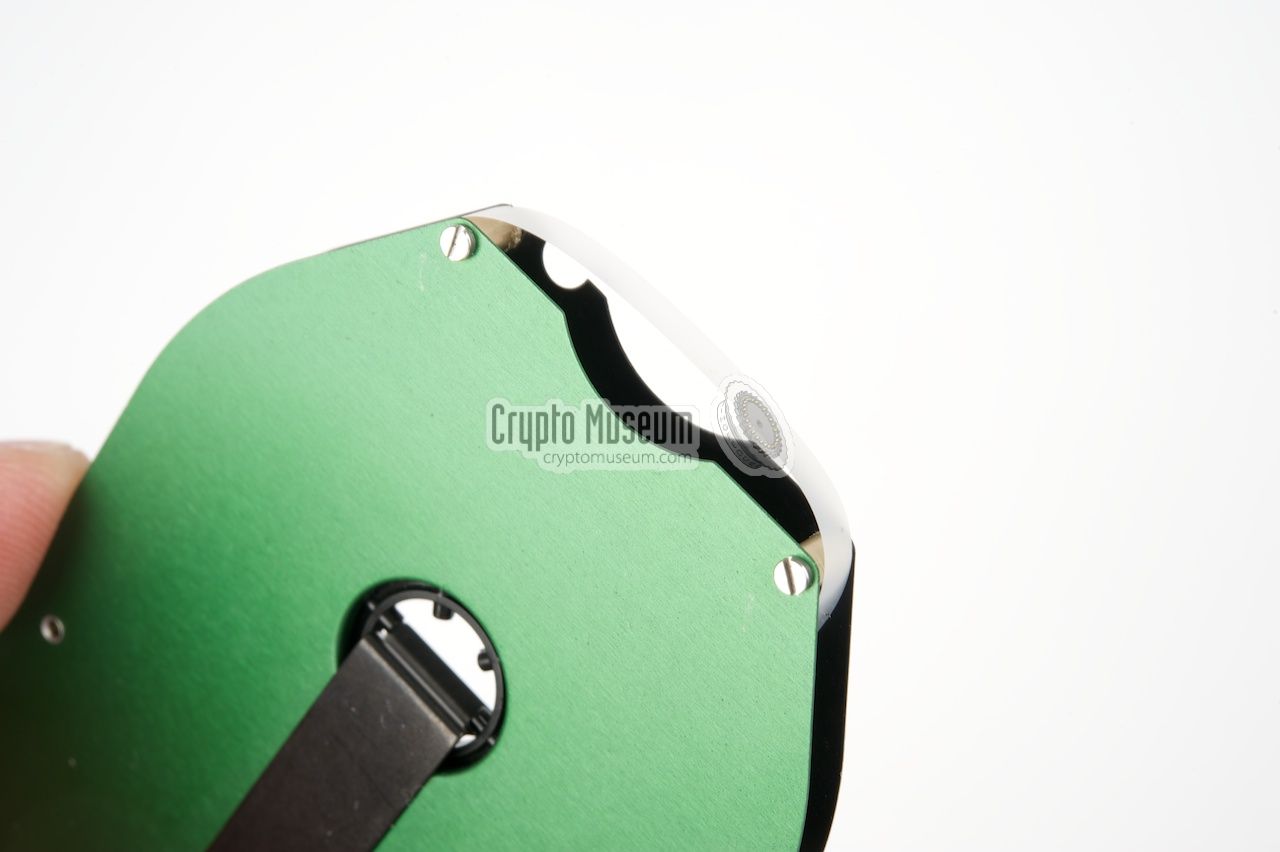
which is open at all sides.
|
At the beginning and the end of the
cassette is a transparent piece of lead-in/lead-out tape that is used
by an optical sensor on the sub-frame to sense the tape-end
and stop the mechanism.
At one of the short sides of te cassette,
the tape is exposed and can be touched.
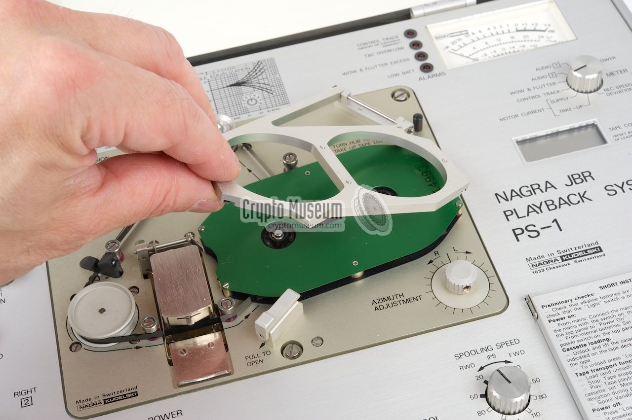
When loading the tape into the PS-1,
this is where the tape has to be pulled-out carefully with a
smooth non-metal tool. Pull it out just enough to guide it over the
tension arm, the large roller and the playback head,
as indicated by the arrows on the sub-frame and shown in the image on the right.
|
|
|
Once the tape is loaded, the cassette holder can be
closed by pushing it
down into the lock at the front,
after which the PS-1 will wind the tape
back until the appropriate tension is sensed. The PS-1 is now ready for use.
Whenever the cassette holder is opened, or when the tape breaks during normal
use, the PS-1 will automatically enter LOAD mode again and release the tape.
The separate JBR
records its audio onto a 3.81 mm chromium dioxide tape
with three channels:
two independent 1.2 mm audio channels plus a 0.4 mm control track
at the centre. The latter is used for a 5,461 Hz reference signal that allows
the PS-1 playback system to correct for speed variations later.
The tape runs at a constant speed of 2.38 cm/s (15/16 ips) ± 2%.
Depending on the thickness of the tape, the recording time is 90 minutes
(12µ) or even 2 hours (9µ).
|
|
Some functions and features, that are not normally needed by the average user,
are hidden in the software. They can be accessed by pressing the red NUM key
on the key pad at the bottom right (normally covered by a flap), followed
by a three digit code.
The following codes are available in versions 1.0 and 1.1 of the firmware:
|
000 Neutral code, no effect 001 Inhibit automatic low batt power off 002 Bypas the Time Base Corrector (TBC off) 003 Enable the built-in Time Base Corrector (TBC on) 004 Normal automatic Time Base Corrector switching 005 Bypass the audio expander 006 Normal automatic audio expander switching 007 Use tape roller speed stabilizer only (also bypasses the TBC) 008 Use control track speed stabilizer only 009 Automatic switching between tape roller and control track stabilizer 010 Set duration of 'backspace' footswitch 1 011 Inhibit fast spooling speed
100 Cancel all settings, except for command 010 2 201 Display the software version number momentarily
|
|
In addition, the following error codes may appear on the display:
|
01 Non existing numeric code requested 02 Illegal time setting attempt (e.g. 64 seconds) 03 Requensted tape position not found
|
-
The default backspace setting is 2 sec. It can be set between 0 and 9 sec.
This setting is retained when command 100 is executed (reset all).
-
Note that command 100 is automatically executed each time the PS-1
enters LOAD mode (e.g. when pressing LOAD or when removing a tape).
|
In the mid-1980s, the FBI
had a growing need for a sub-miniature
undetectable tape recorder for critical surveillance tasks and wiretapping.
As no portable tape recorder
at the time met the tough specifications of the FBI - not even
the Nagra SN - the FBI teamed up
with Nagra Magnetics Inc., the US subsidary of the Swiss
Nagra Company,
to see if a proprietary unit could be developed [1].
It was decided that a new tape recorder would be designed, which would
be smaller that any existing professional surveillance recorder and that
would be virtually undetectable.
On behalf of the FBI, Jim B. Reames helped the design
team. It has been rumoured that his initials (JBR) were used as the name for
the device, but this has neither been confirmed nor ignored by NAGRA [1].
In order to keep the new device
as small as possible, it was decided to
leave the play-back facilities out. Furthermore, the JBR had no erease head
and used an uncommon frequency (32 kHz) for the recording bias signal.
This frequency is also used by digital watches and would not be noticed
by the recorder detectors that were commonly used at the time.
As the JBR is housed in a solid aluminium enclosure, the remaining
unwanted emission is kept to a minimum. For playback, the separate
PS-1 device was developed, which became available a few years later.
As the US Government did not want the JBR to become available to other
users, or even publicly known, it was decided to keep the device secret.
It was not mentioned in any brochure and it was
never shown and demonstrated at technology shows. All marketing for the unit
had to be done via word of mouth.
In September 1990, Nagra wanted to advertise the JBR in the Law and Order
magazine, but received a letter from an undisclosed US Government agency
that prevented them from doing so. If they did, the letter stated,
NAGRA would lose all US Government contracts [1].
Besides the FBI, there were two other US Government agencies who had access
to the newly developed JBR technology (one of which was probably the CIA).
Later, other US Government
Agencies were allowed to use the JBR too, and even some Canadian and British
agencies were given access to the new technology.
|
|
Like all other Nagra products, the PS-1 is built to the highest possible
manufacturing standards, both mechanically and electronically, and is very
service-friendly. The interior can be accessed by removing four screws,
two at the front and two at the rear, after which the top panel comes off.
|
Once the top panel has been removed, the first set of PCBs becomes
visible. At the left are the control switches for the
equalizer and the expander.
At the front are the
tape controls
and the power switch, with an
LDR that automatically dims the light when the
unit is used in the dark. The lights can also be switched off completely.
At the right is the central processing unit, built around an
NSC800 (Z-80) microprocessor
that is hidden under the display.
The CPU consists of the processor, an I/O expander, 2KB of RAM
and an EPROM with the firmware; in this case 1.1.
|
|
|
At the center is the spring-suspended sub-frame with the mechanical
parts. So far, all the parts and circuits are mounted to a horizontal
frame that is bolted to the case. After removing four more screws,
two at the top front and two at the top rear, the hinged frame can be raised.
|
The motherboard takes up most of the bottom section and holds
no less than 12 sub-boards, each of which contains a
particular circuit. Each sub-board is implemented as a plug-in
card that can be swapped within seconds.
There are separate audio amplifiers, equalizers
and expanders for each channel plus boards for the optical
encoder and the control track driven servo system.
One of the most important circuits is the Time Base Corrector (TBC)
which is built around two RD5106ANP
analogue delay lines [5] each of which provides an adjustable audio
delay between 512µs and 1s. This is sufficient for cancelling out even
the smallest speed variations in the recorded signal, within a certain window.
Three such TBCs are available: one for each audio channel and
one for the control track. The latter is the master TBC
that controls the other two.
|
Any analogue audio recording contains small timing errors that are caused
by variations in rotational speed of the mechanism. These variations will
result in a frequency-modulated (FM) component in the recorded signal.
Errors of this type are commonly known as wow and flutter [6] and
consist of two components: slow 0.1-10 Hz variations (wow) and fast ones
>10 Hz (flutter).
Normally, it is good practice to reduce the wow and flutter as much as
possible in the recording device, e.g. by adding a flywheel to a tape
recorder. In the Nagra JBR recorder however, the flywheel is omitted
in order to reduce the size and weight of the device. Instead is has an
advanced tape speed measuring system that controls the speed of the motor.
This guarantees a more or less constant tape speed, but cannot compensate
any short-term variations in speed.
To solve this problem, a 5.461 kHz reference signal is recorded onto a
third track on the tape. This track is located in between the two audio
tracks at the centre of the tape and is called the control track.
During playback (i.e. in the PS-1), the signal from the control track
is used to calculate any timing errors in the recorded signal.
By temporarily storing a number of audio samples in a piece of memory (buffer)
at varying speed, and reading them out at a constant speed,
most short-term errors will be corrected. This process is called:
Time Base Correction.
A Time Base Corrector (TBC) can only compensate for errors within a
certain time frame or window, which is limited by the size of
its buffer. Reaching the end of the buffer will cause a buffer overrun
and result in a TBC error. To avoid this, the calculated error is also
used to increase or decrease the overall tape speed by adjusting
the motor management system accordingly (servo).
The latter is a correction for any long-term speed variations.
A TBC can be implemented in two ways: in the analogue domain and in the
digital domain. At the time the PS-1 was developed (1985), digital
solutions were available but were costly in terms of money, size, weight
and chip count. This problem was solved by using a so called
bucket brigade device (BBD) [7],
which is actually a clock-controlled variable analogue delay line
in a single chip.
Inside the PS-1,
an RD5106A BBD-chip
[5] from the US manufacturer Reticon was used. It offers a variable
delay between 512µs and 1s and accepts clock signals between 500 Hz
and 1 MHz.
In case the errors on the tape are too large, or if the control track
has been damaged, the cure might be worse than the disease.
In such cases the error lights on the control panel will be lit and
it is advised to bypass the TBC.
Furthermore, it is possible to use a proprietary external TBC that can
be connected at the rear. Please note that, if an external TBC is used,
the two red switches and the center of the
motherboard should both be set to EXT
(or back to INT for the internal TBC).
|
- Full Disclosure, The War on Privacy Hits You in the Pocket Book
Full Disclosure Newspaper, Libertyville, Illinois (USA). 1991
Retrieved July 2014.
- Nagra, Production overview and quantities
Internal Nagra document. Date unknown, but probably 2000.
- Nagra Kudelski, PS-1 playback system
Product brochure, 2 pages. June 1092.
- Nagra Kudelski, PS-1 Instruction manual
Nagra PS-1 playback system for Nagra JBR cassettes. October 1987.
- AG&G Reticon, RD5106A/RD5107A Analog Delay Line
September 1991. Retrieved July 2014.
- Wikipedia, Wow and flutter measurement
Retrieved July 2014.
- Wikipedia, Bucket-brigade device
Retrieved July 2014.
|
|
|
|
Any links shown in red are currently unavailable.
If you like the information on this website, why not make a donation?
© Crypto Museum. Created: Thursday 10 July 2014. Last changed: Thursday, 02 February 2023 - 16:47 CET.
|
 |

|
|
|