|
|
|
|
|

|
The image on the right show the Russian KGB bug.
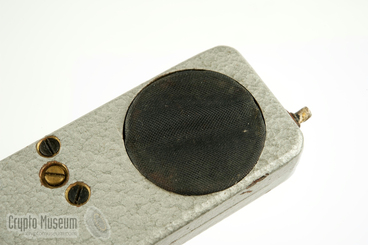
The device measures 75 x 24 x 12 mm and is housed in a metal enclosure.
It has three contact pins to which the power supply and the antenna are
connected. The large black circle at the left is front of the
crystal microphone.
The electronic circuit
is extremely simple and consists of just one
(Germanium) transistor, a simple coil and a couple of passive components.
The tuned circuit
consists of an adjustable 5 mm Ø coil with five windings,
with a 30pF capacitive (crystal) microphone connected in parallel.
|
|
|
As the bug is based on a free-running oscillator, it is rather unstable
and sensitive to power variations. In order to reduce the so-called
hand effect, the transmitter is built inside a
metal enclosure.
Furthermore, the frequency is adjusted by moving a (grounded) core
towards the coil. As this core is grounded, a normal screwdriver can
be used for the frequency adjustement
at the side of the unit.
The adjustment can be locked by means of another screw that is located
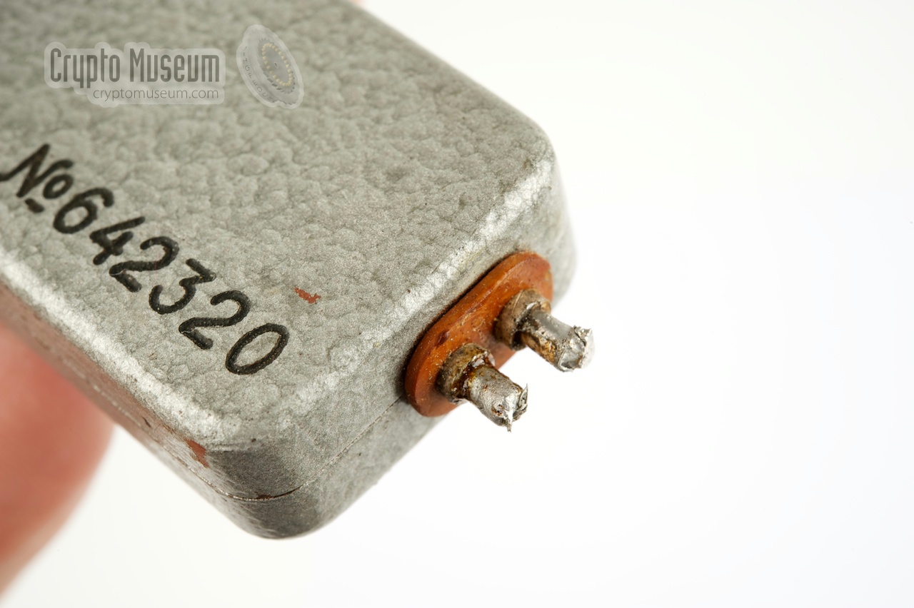
at the top surface. Power is connected to the
two-pin terminal
at one of the short sides (right).
When eavesdropping on a conversation, the capacity of the crystal microphone
will vary slightly, causing variations in the resonance frequency of the tuned
circuit, which effectively results in a Frequency Modulated (FM) signal.
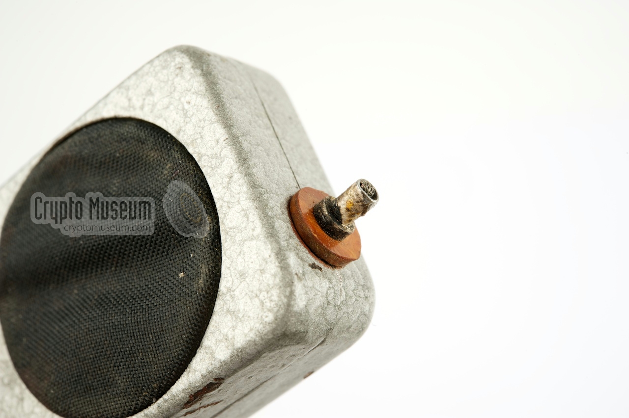
The KGB bug shown here was ideally suited for a wide variety of concealments,
such as a piece of furniture (e.g. the leg of a table)
or a decorative table piece. An external power source (e.g. a battery) was
connected to the 2-pin terminal
at the right, while a wire antenna was
connected to the single terminal
at the opposite side (above the microphone).
Due to the simple nature of this bug, it is easily detected and discovered.
Considering the fact that the Russians also made more sophisticated
– far less easy to find – bugs in the same era, it seems likely that this
one was a bait that was sacrificed in the hope that the more
sophisticated ones were not discovered. In most cases, more than one bug,
each using a different operating principle, would be hidden at the target
area, in the hope that at least one would not be found.
|
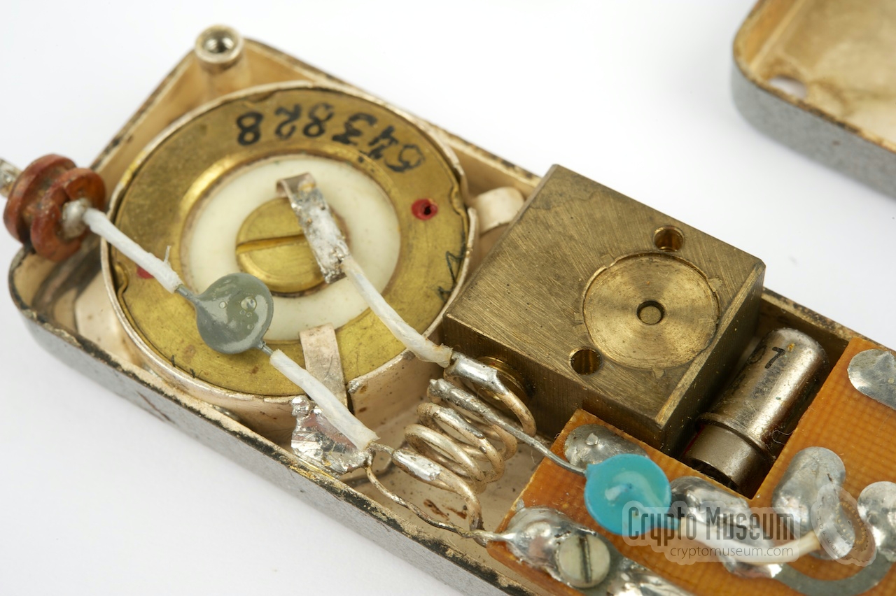
The KGB bug is housed in a molded brass enclosure that consists of two shells, held together by two recessed screws at the bottom. The two case-halfs
are painted in grey hammerite on the outside,
and are silver-plated on the inside. Below is the device
with the bottom shell removed.
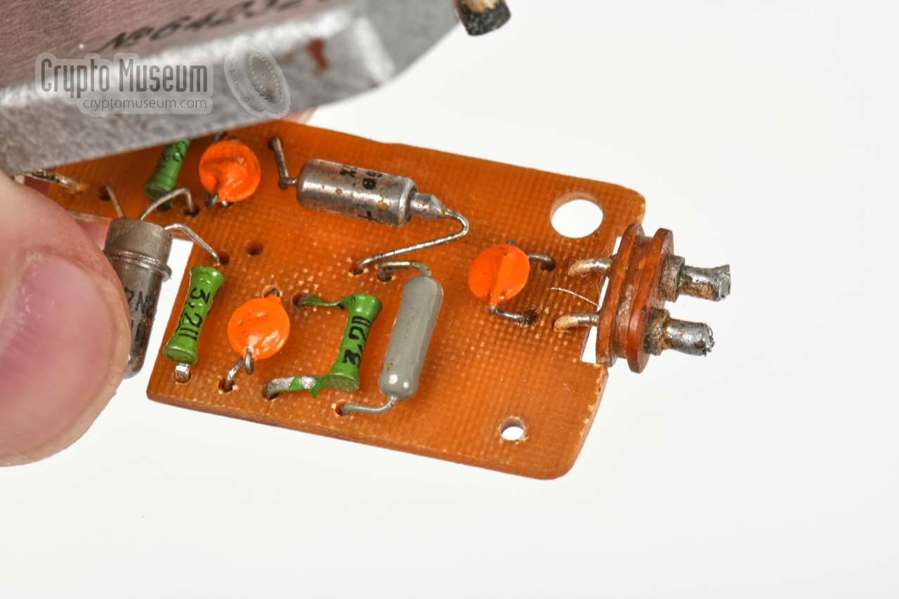
The interior consists of a
printed circuit board (PCB), a tuned circuit and
a crystal microphone. The PCB contains the passive components, whilst the only
active part – the 2N499 transistor – is visible in the gap at the centre of
the opposite side.
At the far left is the crystal microphone that forms a tuned circuit with the
coil that is fitted between the microphone and the PCB. To the left of the
2N499 transistor is a brass block with a screw mechanism that allows the transmission frequency to be adjusted by moving a brass core
in and out of the coil, and locking it in place.
|
Below is the circuit diagram of the 1964 KGB listening device featured here,
as taken down from the actual device. The circuit is built around a single
Philco 2N499 Germanium PNP transistor
[1], which forms a straightforward oscillator
in grounded-base configuration. The tuned circuit is at the bottom right, and
consists of a coil (L1) (5 windings on 5 mm) and a crystal microphone with an
internal capacity of 30pF. Power is applied via a diode at the top left
to ensure correct polarity.
The antenna is connected at the bottom right, at the first winding of the coil
from ground. A brass block allows a metal core to be inserted into the coil, in
order to adjust the frequency in the range 110 to 120 MHz. The device in our
collection is tuned at 116 MHz. Despite the fact that it is merely a simple
free-running oscillator, the circuit is surprisingly stable and doesn't suffer
too much from the so-called hand-effect. The device has a range of approx.
100 to 200 metres.
Audio in the bugged room is picked up by the crystal microphone at the bottom
right, and is Frequency Modulated (FM) directly onto the tuned circuit, by the
virtue of the fact that the microphone's capacity varies slightly with
the sound. Tests have revealed that it is not very sensitive.
|
Type Free-running Frequency 110 - 120 MHz Modulation FM Microphone Crystal Power 4.5 to 6V DC Dimensions 76 × 24 × 11 mm (86 × 24 × 11 mm with terminals) Weight 54 grams Range 100 to 200 metres Year 1964
|
|
|
|
Any links shown in red are currently unavailable.
If you like the information on this website, why not make a donation?
© Crypto Museum. Created: Friday 29 April 2016. Last changed: Tuesday, 11 August 2020 - 05:59 CET.
|
 |

|
|
|