|
|
|
|
|

|
|
CIA NRP EC URS-3 → ← TEC-2
Path loss survey system · 316 MHz
URS-1 was a complete test system for investigating the path attenuation
or path loss in a specific 316 MHz covert radio system, developed
in 1971 by the Dutch Radar Laboratory (NRP)
for the US Central Intelligence Agency (CIA).
It was used to analyse the link budget 1 of the communications system,
of which a series of tailor-made
Sleevex antennas formed an important part
[2].
|
The Sleevex antennas and the URS-1 were developed by the NRP especially
for communication projects of the CIA in the 315 MHz band,
as part of a long-term research contract under the name
Easy Chair.
A Sleevex antenna is no thicker than 10 mm
and is basically a vertical dipole that is fed by a coaxial cable via one
of its conductors. This antenna type is known as a coaxial antenna
or sleeve antenna. Specific versions were made for use in free space,
concrete and wood. They were also made for other frequencies.
The CIA used the URS-1 also for training purposes.
|
-
In a telecommunications system, the link budget is the sum of all gains
and losses from transmitter, through the medium to the receiver.
➤ Wikipedia
|
The diagram below shows the basic setup of the URS-1 system.
At the left is the transmitter that is fed by a 9V battery which is
installed at the bottom end. An external dynamic microphone can be
connected to it, but it can also be replaced by a shorting link,
in which case the transmitter produces a constant beep.
The transmitter is normally connected to one of the Sleevex antennas.
At the right is the URR-1 receiver that should be connected to the
SRN-9M reference antenna. The receiver produces a visible output on an
indicator at its front panel,
and an acoustic one through a suitable pair of headphones.
An extra output is available for connection of a recorder.
|
The illustration below shows some of the factors that attribute to
path loss, starting with the type and position of the bug and its
antenna at the target area.
The transmitter's signal is attenuated by the distance to the receiver,
the material in which the antenna is embedded, the walls of the building,
any furniture, and by anything else that is in the signal path to the
Listening Post (LP).
Other factors may attribute to the gain of the signal,
such as the transmitter's output power, the gain (if any) of its antenna,
the gain of the receiving antenna and any pre-amplifiers.
In order to predict the propagation of the signal with some
degree of reliability, it may be useful to calculate the sum of all gains and
losses and compare it to the link budget of the entire system.
A detailed path loss survey was usually carried out by the CIA
before planting a bug at a given target.
|
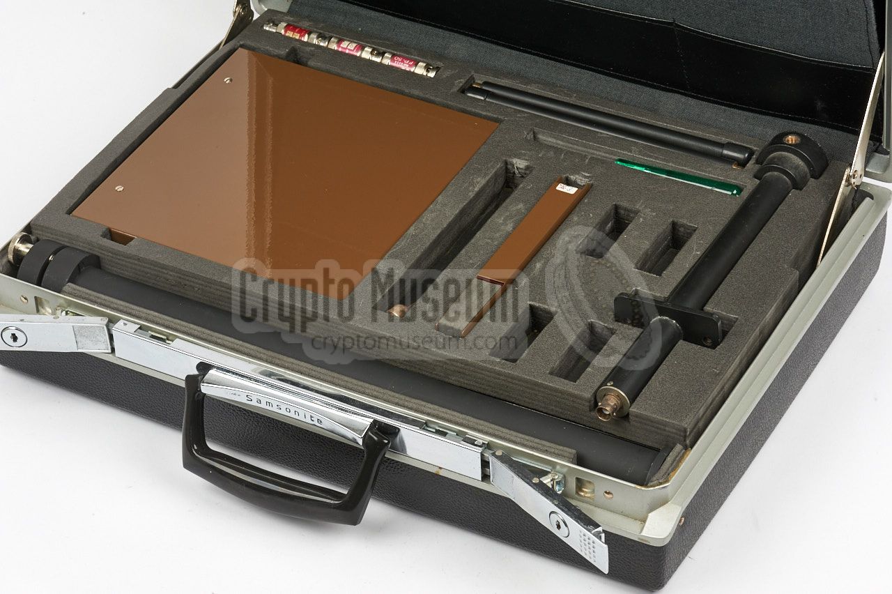
The diagram below shows how and where the various items are packed inside
the Samsonite briefcase.
The bottom section is removable and gives access to a further compartment
that contains the accessories, cables, adapters, spare
parts and a collection of Sleevex antennas.
|
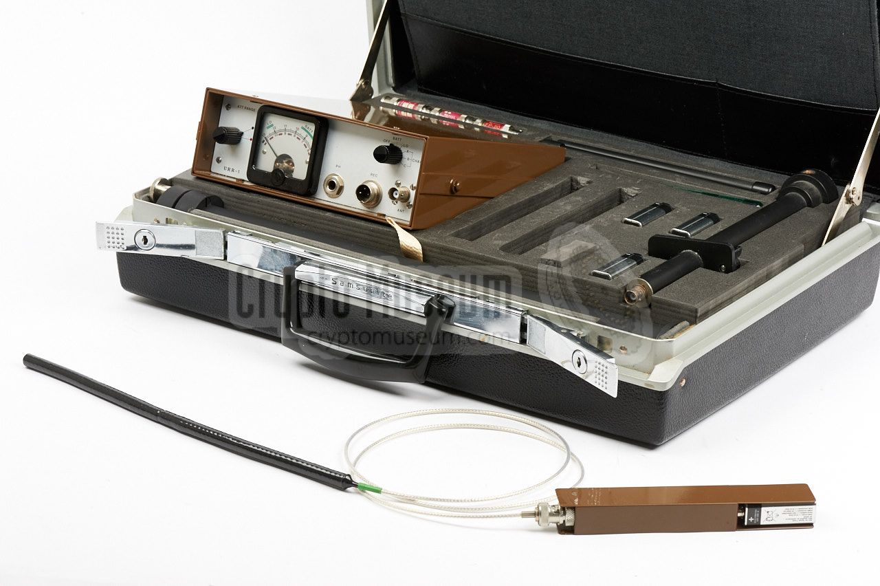
All parts and accessories of the URS-1 survey system were supplied in the
standard Samsonite executive style briefcase shown in the image on the right.
The documentation and the reflector of the receive antenna are stowed in the top lid.
All other parts are stowed in the bottom part, that consist of two layers.
The transmitter and the receiver are directly accessible. Adapters and cables
are stored in the bottom section.
|
|
|
The transmitter measures 160 x 27 x 19 mm, including the 9V battery that
powers it. It works on a single crystal-operated channel (314.500 MHz in
this case), with an optional tone or voice modulation. A microphone can be
connected externally to the solder terminal on top of the device. The
transmitter has a BNC socket for connection of a Sleevex antenna.
Unlike other bugs, such as the SRT-107,
the URT-1 does not provide
audio masking and will therefore be much easier to detect.
➤ More information
|
|
|
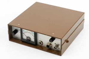
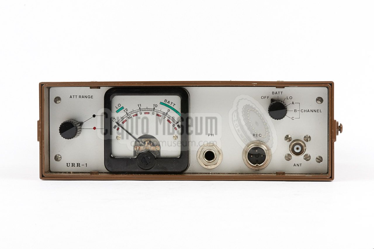
The URR-1 receiver was designed especially for path loss measurements and
can best be seen as a calibrated field-strength meter for the 314-316 MHz
frequency range. It should be used in combination with the
SRN-9M receive antenna.
It has three crystal operated channels: (A) 314.5 MHz, (B) 315.5 MHz and
(C) 316.5 MHz. The receiver is powered by two 9.5V batteries that are fitted
in a small compartment at the rear.
➤ More information
|
|
|
The SRN-9M was supplied as a reference antenna for the URR-1 receiver.
It is basically a center-fed half-wave (½λ) open dipole that is
placed before a reflective shield. The total gain of this antenna is estimated
at 8.5dB.
Inside the boom (between the two dipole elements and the reflector) is
a BALUN that provides correct matching to the coaxial transmission line.
➤ More information
|
|
|
The URS-1 set was supplied with two complete sets of Sleevex antennas
(three models each), so allow simultanious testing with two independent
transmitters in combination with the URR-1 reference receiver.
Each Sleevex antenna has a colour coded ring at its base, that indicates
the environment (medium or diëlectricum) for which it has been designed.
➤ More information
|
|
|
The URR-1 receiver delivers its audio to a pair of headphones that can
be connected to the 6.3 mm jack socket at the
front panel. In addition,
the received signal can be recorded onto a (tape) recorder, via the
3-pin DIN socket at the front.
A suitable cable
for connection to a recording device was provided with the set.
It is shown in the image on the right.
|
|
|
In order to obtain a proper and calibrated result from the measurements,
it may be necessary to attenuate the signal that is intercepted by the receiver.
For this purpose,
three calibrated 20dB attenuators
are supplied with the set.
The image on the right shows a single 20dB attenuator, that can be inserted
directly between the antenna and the RF input of the receiver. Note that the
actual attenuation is slightly frequency dependent, as indicated on the label.
|
|
|
The URS-1 was supplied with a complete technical manual, that contains the
full circuit diagrams of the transmitter and the receiver, plus full circuit
descriptions.
In addition, it provides detailed information about path loss measurements
and antennas, and gives instructions and tips on how the measurements are best
carried out in order to obtain the most reliable results.
This manual does not contain any classified information.
➤ Download the manual
|
|
|
Device Path loss survey system Model URS-1 Manufacturer NRP Customer CIA Years 1971-1977 Frequency 314.5 MHz, 315.5 MHz, 316.5 MHz Transmitter URT-1 Receiver URR-1 Antenna SRN-9M
|
1 Samsonite briefcase 1 Receiver URR-1 2 Transmitter URT-1 1 Antenna SRN-9< 4 Battery 9V for transmitters 1 Screwdriver 1 Various coaxial cables 6 Sleevex antenna 3 Attenuator 20dB 1 Headphones 1 User Manual
|
|
URS
|
|
Universal Radio System
Complete system for carrying out reference measurements.
Also used for training purposes.
|
|
URT
|
|
Universal Radio Transmitter
Simple transmitter for training perposes and for reference measurements.
Supplied as part of a complete reference survey system.
|
|
URR
|
|
Universal Radio Receiver
Universal receiver for reference and field-strength measurements.
To be used under varuing conditions, in order to obtain the best possible
propagation of the signal.
|
|
|
|
Any links shown in red are currently unavailable.
If you like the information on this website, why not make a donation?
© Crypto Museum. Created: Tuesday 03 January 2017. Last changed: Sunday, 26 May 2024 - 11:50 CET.
|
 |

|
|
|