|
|
|
|
|

|
|
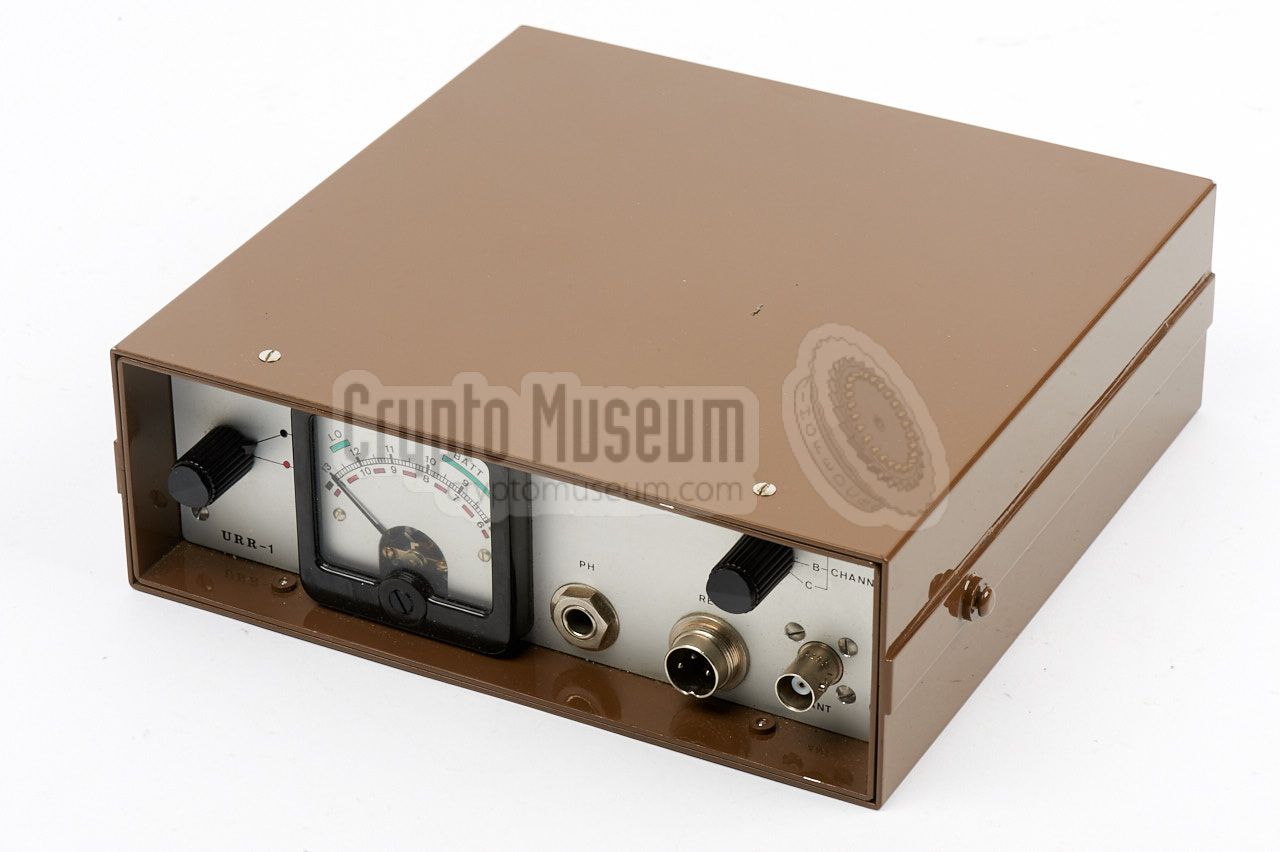
← Easy Chair ← URS-1 CIA NRP
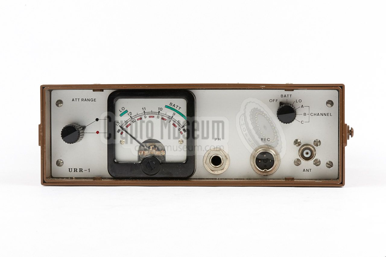
All controls and connections of the receiver are located at the front panel.
|
The receiver have been cleverly designed.
The circuit works as follows:
The calibrated output of a local oscillator (LO), is directly mixed
with the input signal from the antenna by means of a directional coupler.
The resulting mixed signal in then fed to a mixer/detector diode.
The frequency difference between the input signal and the
local oscillator is just 16 MHz. If the received signal is at
314.500 MHz, the local oscillator is at 314.516 MHz.
This is done so that (pre)amplification, filtering and
logarithmic detection all take place in the low frequency domain:
LC resonant circuits can be created with a rather high Q-factor
to ensure small bandwidth in the IF-stage of the receiver.
This way, a 65dB sensitivity span has been obtained.
Using three external attenuators of 20dB each, in combination with
the 65db sensitivity span, results in a usable
path loss range from 0dB to -125dB.
Signal leakage at the antenna terminal is less than -23dB.
For further details, check the circuit description
in the technical manual.
|
|
|
|
Any links shown in red are currently unavailable.
If you like the information on this website, why not make a donation?
© Crypto Museum. Created: Saturday 07 January 2017. Last changed: Tuesday, 13 June 2017 - 06:27 CET.
|
 |

|
|
|