|
|
|
|
|

|
|
CIA NRP EC URS-4 → ← URS-1
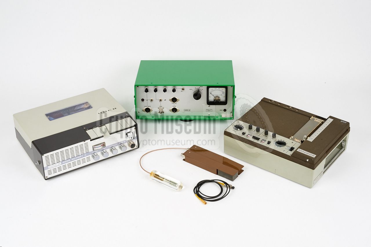
The complete URS-3 system was supplied in two Samsonite briefcases.
In its basic configuration, it consists of an URT-3 transmitter
with Pulse Position Modulation (PPM), an URR-3 receiver, suitable
antennas
and a range of accessories.
When doing a site survey, the measurements could be recorded
on paper, using the supplied pen recorder,
and/or on audio tape,
using an optional UHER tape recorder.
This allowed the survey to
be reviewed later. In some cases, an additional
Replay Unit was supplied, allowing the results to be viewed
without access to a receiver.
|
|
|
|
The URS-3 did not replace the
URS-1 path loss survey set,
but was used complementary to it, as it supports the 1380 MHz band,
whilst the URS-1 was used for measurements in the 316 MHz band.
Both systems were used extensively in the following 20 years
(at least). The URS-1 was eventually succeeded by the
URS-4 in 1980,
which added support for VHF-H band (170 MHz).
Note that the URS-3 is a wideband system (25 MHz) whereas the
URS-1
and URS-4
are both narrowband systems (30 kHz).
Together, the URS-3 and URS-4 covered all CIA frequency bands.
|
-
In a telecommunications system, the link budget is the sum of all gains
and losses from transmitter, through the medium to the receiver.
➤ Wikipedia
|
The diagram below shows the basic setup of the URS-3 system.
At the left is the transmitter that is fed by a 9V battery which is
installed at the bottom end. When ON, the transmitter produces a constant
beep that should be picked up by the receiver. An optional external
push-button can be connected to a socket to make the transmitter send a MARK tone, allowing easy
identification at the listening post (LP).
The transmitter is normally connected to an
SRN-58 'plexiglass' antenna.
At the right is the URR-3 receiver that should be connected to the
SRN-55 reference antenna. The receiver produces a visible output on an
indicator at its front panel.
Furthermore, sockets are available for the connection of a
pen recorder
and an audio tape recorder, for later reference.
|
The illustration below shows some of the factors that attribute to
path loss, starting with the type and position of the bug and its
antenna at the target area.
The transmitter's signal is attenuated by the distance to the receiver,
the material in which the antenna is embedded, the walls of the building,
any furniture, and by anything else that is in the signal path to the
Listening Post (LP).
Other factors may attribute to the gain of the signal,
such as the transmitter's output power, the gain (if any) of its antenna,
the gain of the receiving antenna and any pre-amplifiers.
In order to predict the propagation of the signal with some
degree of reliability, it may be useful to calculate the sum of all gains and
losses and compare it to the link budget of the entire system.
A detailed path loss survey was usually carried out by the CIA
before planting a bug at a given target.
|
The first designs for the URS-3 date back to November 1972, when, at the
request of the CIA, development was started of a path loss survey set
that would be suitable for the newly assigned L-band (1000-1600 MHz).
At the time, this band was relatively free from congestion and
counter-surveillance.
The existing URS-1 set
was only suitable for the 315 MHz band [A].
After several experiments and design changes, the first XURS-3 prototype was
delivered to the CIA in August 1974. The evaluation led to further changes
and modificiations to the design. The final design was ready for release
in December 1975. The set was officially released during the course of 1976.
In 1980 is was complemented by the URS-4,
which shared the same user interface, but offered narrowband support
for the VHF (170 MHz) and UHF (416 MHz) bands.
|
All parts and accessories of the URS-3 survey system were supplied in two
standard Samsonite executive style briefcases, such as the one shown in the
image on the right. The manual and the antennas are contained in the set.
All accessories are stowed in the bottom part, that consist of two layers.
The transmitter and the receiver are directly accessible. Adapters and cables
are stored in the bottom section.
|
|
|
The URS-3 came with a dedicated calibrated transmitter, the URT-3,
that transmitted on a fixed spot frequency in the 1380 MHz band
using Pulse Position Modulation (PPM). It was powered by a
standard 9V battery and had a button for sending an identification
tone.
Unfortunately, the URT-3 is not in our collection, so we are
unable to provide an image of it at this time.
No image available
|
|
|
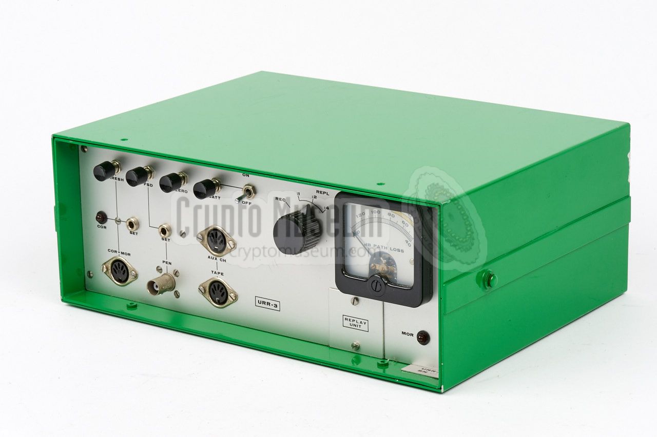
The URS-3 came with a fixed-frequency receiver, the URR-3,
that was set to the same 1380 MHz spot frequency as the URT-3
transmitter. The receiver has outputs for headphones,
audio tape recorder
and pen recorder.
Recorded surveys can be played back for processing at a later moment.
As we don not have a full URR-3 receiver in our collection,
we are instead showing an image of the Replay Unit,
which is nearly identical.
➤ More information
|
|
|
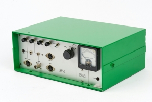
The optional URR-3 Replay Unit could be used in addition
to the URR-3 Receiver. It is housed in the same enclosure,
and has all parts fitted, except for the RF front-end and the
IF-stage.
The Replay Unit could be used at the head office, for replaying
the data from a recorded survey. If necessary, it could later be
converted into a complete URR-3 by installing an upgrade kit.
➤ More information
|
|
|
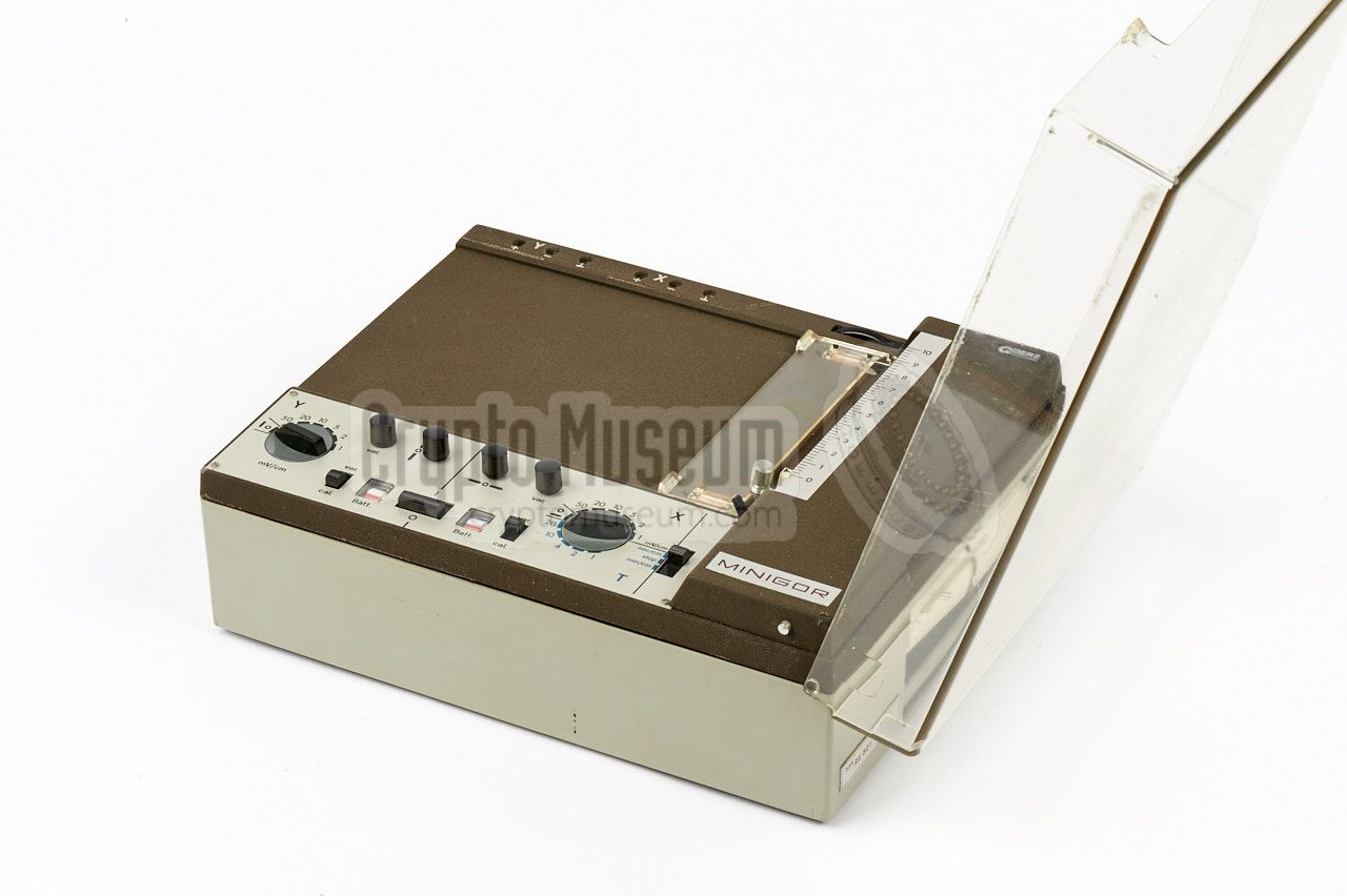
When performing a site survey, the results of the path loss
measurements can be printed onto paper, using the Goertz
RE-501 MINOGOR pen recorder shown in the image on the right.
The device is battery powered and prints the data, relative
to time, onto a 20 cm wide thermal paper strip for later
processing.
|
|
|
In addition to printing the measurement data onto paper,
it was also possible to record it onto a magnetic (audio)
tape, using the UHER recorder shown in the image on the right.
UHER tape recorders were very popular during the 1960s and
1970s, as they were among the first affordable portable
tape recorders with professional performance.
➤ More information
|
|
|
A suitable 1600 MHz directional antenna should be used with
the URR-3 receiver, such as the SRN-55 shown in the image on
the right.
Initially, this antenna was not part of the URS-3 survey set,
but from 1977 onwards, it was issued as standard
with every URR-3 receiver.
➤ More information
|
|
|
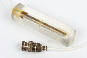
Each URT-3 transmitter was supplied with an sleeve antenna
embedded in a plexiglass stick, that was suitable for the
1500 MHz band.
The same antenna was supplied as standard
with every covert listening device that operated in this
band, such as the SRT-107.
➤ More information
|
|
|
Device Path loss survey system Model URS-3 Manufacturer NRP Customer CIA Years 1975-1980
|
Frequency 1000 - 1600 MHz IF frequency 60 MHz Bandwidth 25 MHz Subcarrier 20 kHz Path loss indication quasi logarithmic SC bandwidth 10 kHz Indicating ranges 30-100 and 60-130 dB Demodulation Compatible with URT-3 Audio out 1 mW into 600 Ω Temperature 0°C to +60°C Power supply Internal, 4 x 9V block battery
|
Frequency Tunable 1000 - 1600 MHz (spot frequency) Pulling figure < 10 MHz Pulse modulation prf 20 kHz average Pulse width 0.2 µs Duty cycle 1 : 250 Peak power output 300 - 3000 mW Power adj. range 5 dB Modulation Pulse Position Modulation (PPM) Audio response 300-5000 Hz at -3dB Indentification 1000 Hz Audio compression 2 x linear dB-wise Audio input 500 µV at 4000 Ω Temperature 0°C - +60°C Power supply Internal 1 or 2 x 9V block battery
|
- Receiver URR-3
- Replay unit URR-3
- Transmitter URT-3
- Pen recorder Goertz Minigor RE-501
- Antenna SRN-58 (with OSM/M plug)
- Calibration attenuator 60 dB
- Remote mark switch and cable
- OSM-BNC adapter cable
- 2 BNC-Banana adapter cables
- 2 DIN-DIN extension cables
- 6 DIN spare plugs
- Amphenol Sumbinax/M spare plug
- 2 Carrying straps
- 10 spare fuses 100 mA
- Extender board for URR-3
- Screwdriver
- Operation and test manual
- Set of official acceptance test data sheets
|
- Engineering Report for XURS-3
NRP, August 1974. CM302516/A.
- Collection of notes, correspondence and circuit diagrams related to URS-3
NRP, December 1975 - November 1976. CM302516/B.
- Manual for URS-3
NRP, November 1976. CM302516/C.
- Manual for URS-3
NRP, December 1976. CM302516/D.
- Proposal for Production of URS-3 Systems
NRP, March 1977. CM302516/E.
- XY-YT Miniaturschreiber Minigor, Type RE 501, Bedienungsanleitung
Goetz, Metrawatt AG, Nürnberg (Germany). Date unknown. CM302559/A.
|
|
|
|
Any links shown in red are currently unavailable.
If you like the information on this website, why not make a donation?
© Crypto Museum. Created: Thursday 10 August 2017. Last changed: Sunday, 26 May 2024 - 12:10 CET.
|
 |

|
|
|


