|
|
|
|
|

|
|
Easy Chair EASYCHAIR CIA NRP
The Russian device, that was also known as
The Great Seal Bug,
was discovered in the study of the US Ambassador in Moscow (Russia)
in 1952, after it had been operational for nearly 7 years.
After its discovery, the CIA started a top secret research project
under the name EASYCHAIR (EC)
with the aim to develop similar devices
based on its technology. The research was carried out in the Netherlands
at the Dutch Radar Laboratory (NRP)
in Noordwijk.
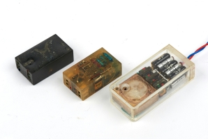
Two prototypes are shown here: one for 1100 MHz and one for 360 MHz.
|
|
|
In between the other developments, the NRP kept working on the cavity
microphone and built several protypes, initially for use on 360 MHz and later
also for 1100 MHz. Finally, in 1965, they had grasped the concept
of The Thing and were able to operate it reliably, using radar pulses. 1
|
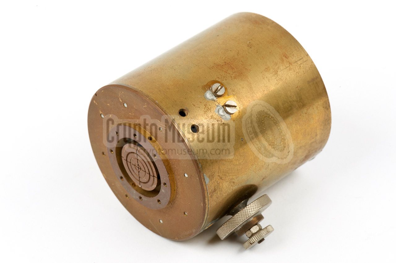
The image on the right shows one of the original prototypes for use on
360 MHz. Although this frequency was probably the most suitable one for
a bugging device in terms of performance, range and path attenuation,
it was less suitable for a device like this in terms of dimensions.
The cylinder has an outer diameter of 6 cm and is 6.5 cm long, and weighs
nearly 600 grams. It is shown here without the aluminium membrane,
or diafragm. The screw at the bottom is used for fine tuning of the frequency.
At the rear side
is a BNC socket for connection of an antenna rod.
|
|
|
Although the NRP was able to demonstrate a working cavity microphone in 1965
— the goal of the initial EASYCHAIR research contract —
the CIA had meanwhile
lost interest in Resonant Cavities and Passive Elements (PEs), mainly because
both the Russians and the Americans had been complaining about excessively
strong RF signals beamed at them by the other party.
As a result, the NRP's resonant cavity microphone was not developed further
and apart from a few prototypes, no further devices of this kind were built.
In order to satify the customer (CIA),
they concentrated on the development of Active Target Elements (ATEs) with
audio-masking facilities.
|
 |
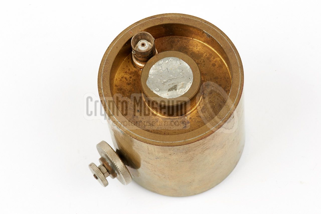
The diagram below shows the 360 MHz version of the NRP/CIA resonant cavity
microphone, as seen from the front (left) and rear (right). The main tuning
is done by adjusting the mushroom-shaped disc at the centre to be as close
to the membrane as possible. It is then soldered in place.
After that, the exact frequency can be fine-tuned with the smaller knob at
the side. Once that is done, the frequency can be fixed with the larger knob,
which effectively secures the smaller one.
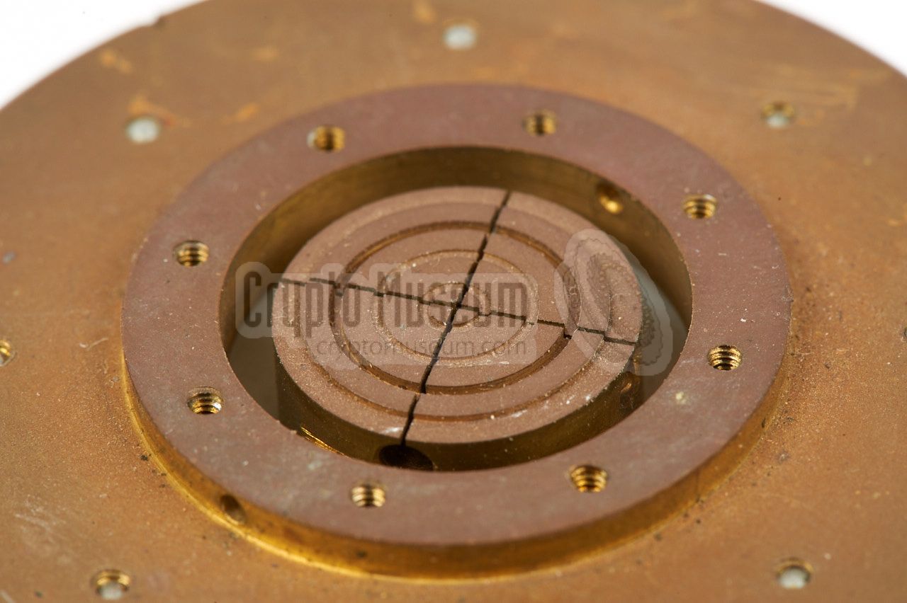
At the front centre is a circular opening through which the head
of a mushroom-shaped tuning post is visible. Together with the membrane (not
shown here), this disc forms a condenser microphone. The grooves in the disc
are for the reduction of pneumatic damping, also known as the cushion-effect.
For a proper understanding of the working principle behind resonant cavity
microphones, we have to take a look at the
original Russian device
that was discovered in 1952:
Although there are some differences between the two designs, such as an
inductive coupling of the antenna instead of a capacitive one, the operating
principle is largely identical. It is important to realize that the frequency
of the activiation beam is the same as that of the reflected signal.
➤ Full description of the Russian device
The diagram below shows a cross-section of the pulsed cavity.
It consists of a cylindrical body with a heavy machined frame at the rear
that holds the adjustable main stem. At the front end,
the stem is held in place by a teflon ring. The front surface of the stem
has machined grooves and forms a capacitor with the aluminium coated maylar
membrane that is mounted in front of it.
A perforated disc holds the thin mylar membrane in place an protects
it against damage. The stem is adjusted from the rear, so that the
air gap between the membrane and the stem is as small as possible.
This gives the highest possible capacity, and the highest sensitivity
to sound vibrations. Once the stem is adjusted, it is fixed in
place by filling the centre hole with solder.
A suitable antenna is connected to the BNC socket at the rear.
Contrary to the Russian original, it is inductively coupled
to the stem - which is also an inductor -
with a rather high transformation ratio, in order to keep the quality
factor (Q) of the entire system as high as possible.
|
The diagram below explains the basic operation of the Pulsed Cavity
System as developed by the NRP. The transmitter at the top right transmits
short pulses that activate the cavity. As a result of its high Q-factor,
the cavity will not immediately stop ringing once a pulse has disappeared.
As the receiver is synchronised with the transmitter,
it will only 'listen' during the gaps between two pulses. The demodulated
audio pulses are stretched in a sample-and-hold circuit, in order to produce
a proper analogue audio signal that is a copy of the sound picked up by
the cavity [C].
The overall timing of the system is provided by a Master Timing Unit.
There are adjustments in many places, which makes it difficult for an
untrained technician to obtain satisfying results. In order make the setup
procedure easier, a performance check oscillator is added at the top.
It can produce a 1350 or 4000 Hz sinewave audio signal for modulating the
transmitted pulses. These audio tones can only be heard through the receiver,
if the cavity is successfully activated and the signal is successfully
demodulated by the receiver. Once adjusted, the system is extremely stable.
As a proof of concept, the first Pulsed Cavity system delivered to the CIA
operated at approx. 375 MHz. The large cavity resonator shown in the images
above was used for these experiments. The transmitter produced a peak
power output in the order of 25 Watts, which was enough to cover a
distance of 50 metres in free space and pass through several walls of the
laboratory building. If necessary, peak power could be enhanced later
to 1-5 kW by using magnetron radar oscillators.
Most of the development of the above 375 MHz system took place in 1963 and
1964, after which a transistion was made to 1100 MHz, using a much smaller
resonant cavity, in combination with the described listening post,
albeit in an adapted form in order to support the higher frequency.
|
|
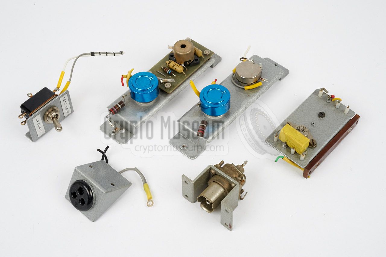
Although it was initially thought that there were no surviving components of
the Easy Chair Pulsed Cavity System, the following items have meanwhile
been rediscovered:
|
This stripline oscillator is the master oscillator,
that provides the basic signal for the transmitter
and is controlled by the pulse generator.
Note that the signal from the pulse generator is first buffered
in the external buffer amplifier.
|
|
|
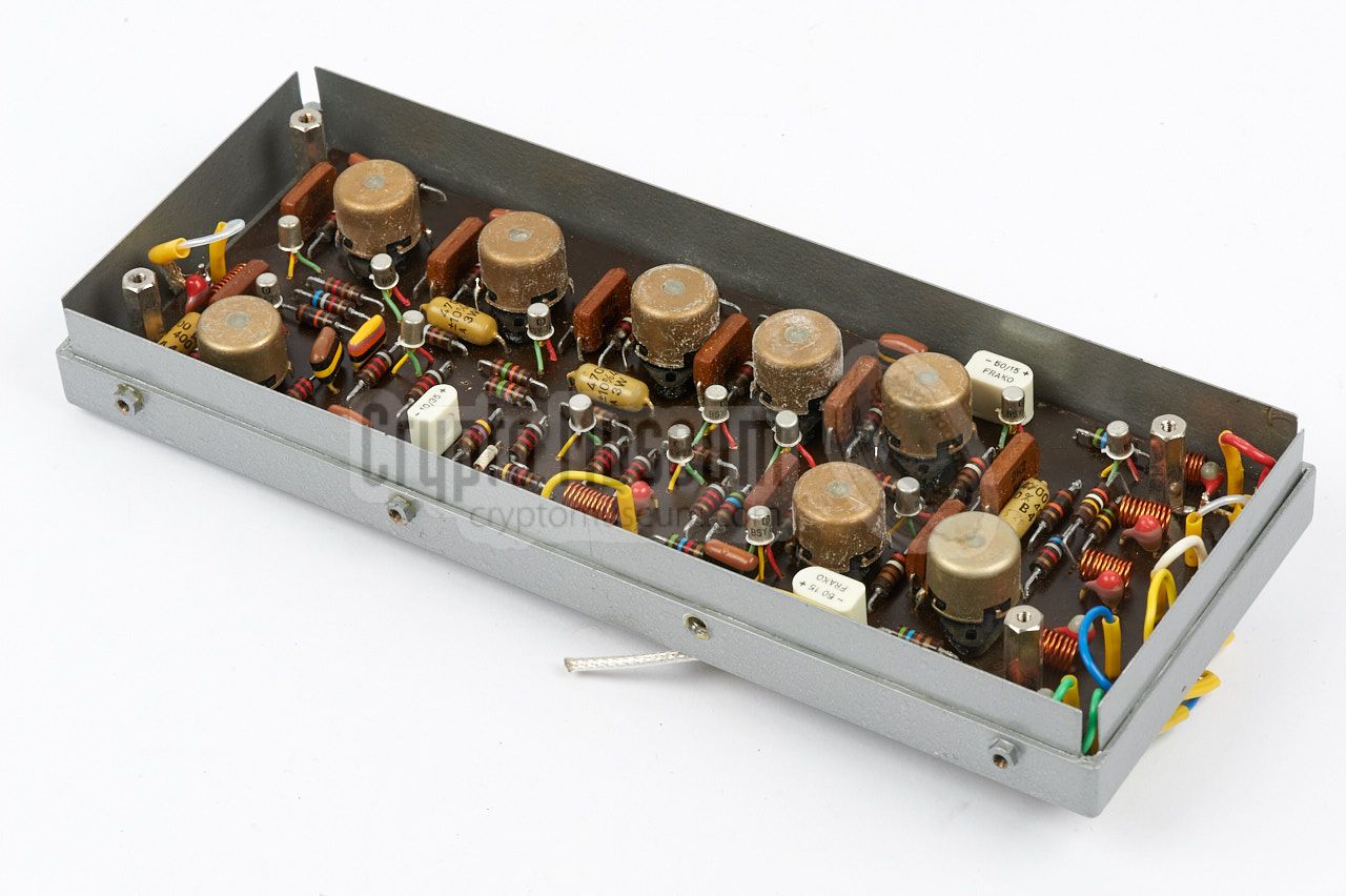
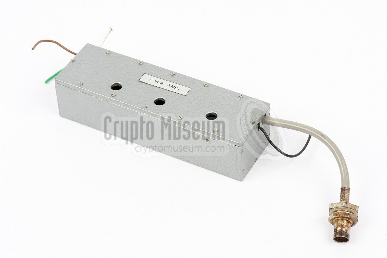
This is the actual transmitter. It takes the (pulsed)
signal from the master oscillator and amplifies
it to an appropriate level. The output of the transmitter
is supplied directly to one of the antennas.
The PA consists of three transistor-based stages, all of
which are clearly visible in the image on the right.
At the right is the fist stage to which the signal from
the master oscillator is supplied. At the centre is the
driver stage built around a 2N3375 transistor. The output
stage at the left is built around a 2N3632 transistor.
|
|
|
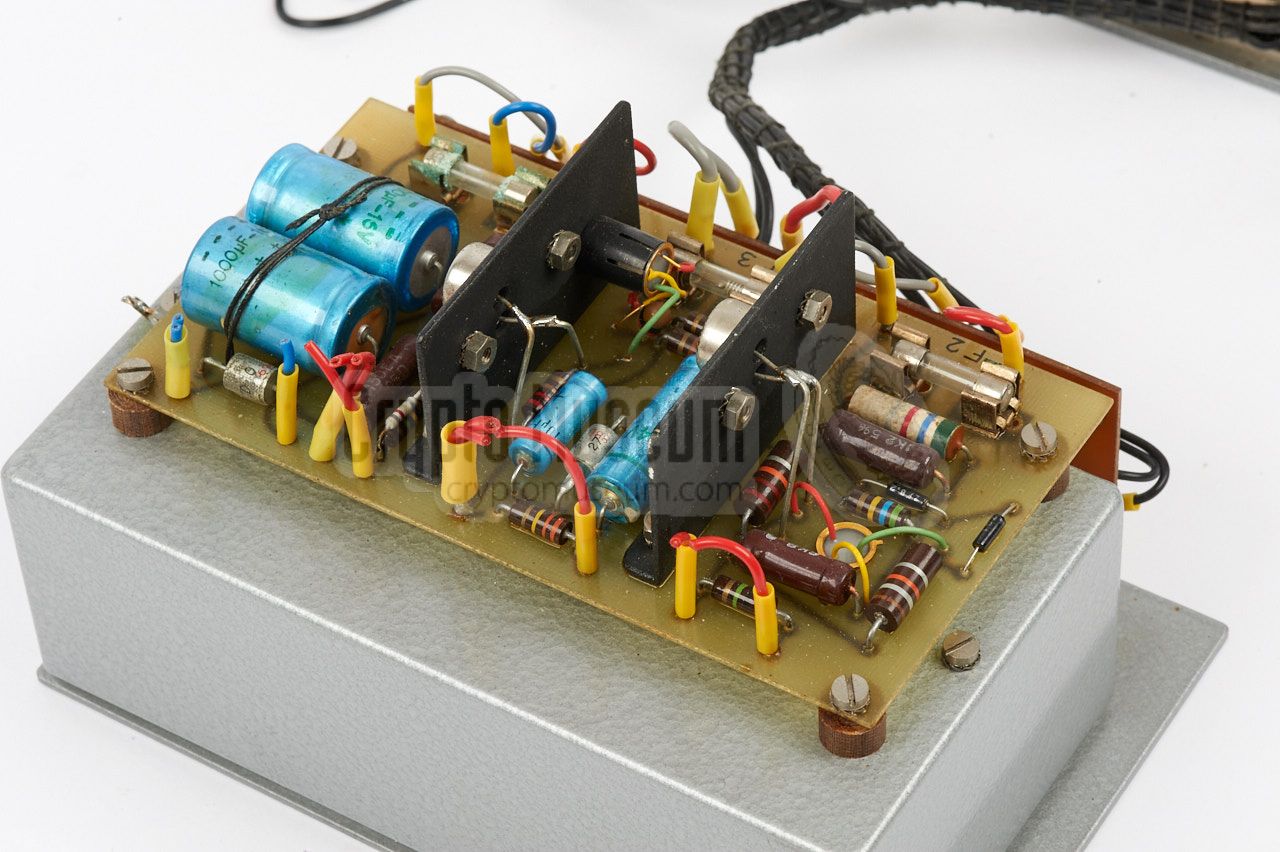
Apart from the PSU, this is the largest component of the
system. It is driven by the master oscillator and
provides the central timing for all other parts. Furthermore
it drives the transmitter, the local oscillator and the audio.
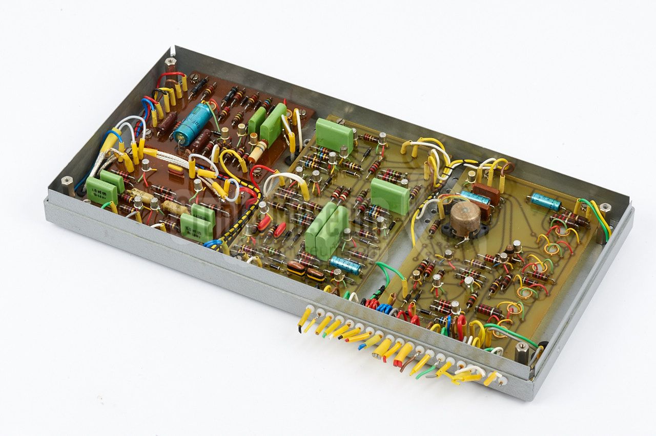
Inside the timing unit are five PCBs. At the top left is the
tuning control unit. At the bottom left is the audio circuit.
The PCB at the center provides the timing and gating signals.
The rightmost PCB contains the transmitter control circuits and
the receiver's AFC gating control.
|
|
|
|
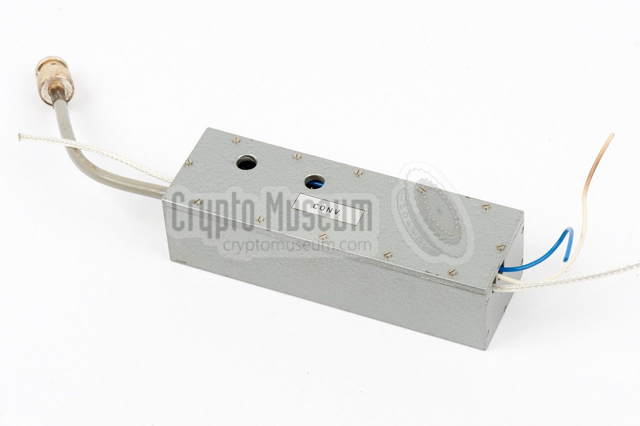
The converter unit (marked CONV) contains the RF front-end
and the mixer. It is connected to the receive antenna and the
local oscillator (LO), and delivers its output to the IF section.
|
|
|
The IF section amplifies the output from the converter,
limit its amplitude and demodulates the Frequency Modulated (FM)
pulsed signal.
The output of the IF section is supplied to the timing unit,
where the pulses are stretched and the resulting (audio) signal
is amplified and filtered, ready for supplying it to a pair of
headphones.
|
|
|
The image on the right shows the complete Power Supply Unit (PSU)
of the listening post. It consists of a regular transformer,
an electronic regulated voltage circuit and a switch panel.
The PSU provides the necessary voltages for the various parts
of the transmitter and receiver.
|
|
|
- 6-Months Summary Report, EC Program, 1963-1964
June 1964. Chapter 3.4 Pulsed Interrogation of resonators.
CM303922.
- Final Research Report, EC Program, 1963-1964
December 1964. Chapter 3.1 Pulsed Interrogation of r.f. resonators.
CM303920.
- 6-Months Summary Report, EC Program, 1964-1965
June 1965. Chapter 2 Progress of pulsed cavity system.
CM303921.
- Final Research Report, EC Program, 1964-1965
December 1965. Chapter 2 Progress of pulsed cavity system.
CM303919. Contains original photographs of cavity microphones.
- 6-Months Summary Report, EC Program, 1965-1966
October 1966. Chapter 2 Pulsed cavity system.
CM303913.
- Final Research Report, EC Program, 1965-1966
January 1967. Chapter 2 Pulsed cavity system.
CM303915.
- 6-Months Summary Report, EC Program, 1966-1967
August 1967. Chapter 2 Pulsed cavity system.
CM303912.
|
|
|
|
Any links shown in red are currently unavailable.
If you like the information on this website, why not make a donation?
© Crypto Museum. Created: Tuesday 07 February 2017. Last changed: Wednesday, 05 November 2025 - 11:39 CET.
|
|

|
|
|