|
|
|
|
|

|
|
UK Phone Voice Scrambler No. 8 Overview → ← No. 7
|
|
Privacy Set No. 9A
TES 64/1
|
|
|
The device is fully compatible with the
earlier models
and was initially used in combination with the old
SA5030 voice terminal. The
terminal was later succeeded by
Telephone No. 710 and 740,
which had a more modern look and feel.
Privacy Set No. 9A was in production from 1964 to 1972 and was made
by several manufacturers. Refubished No. 8 units have
been spotted as late as 1977 [1].
The outer dimensions of the device and the position of
the cable inlets are identical for all versions regardless the
manufacturer, but there are significant differences in the interior.
|
|
|
This page describes specifically the version of Privacy Set No. 9A
that was made in 1964 by the
Telephone Manufacturing Company (TMC),
marked at the bottom of the unit with the batch code TES 64/1 and
production code E526539/3 .
The circuit is comparable to that of Privacy Set No. 8 from
the same manufacturer. It is made
with the first generation of OC71 Germanium transistors.
The device is an improved version of Privacy Set No. 8
with better low-pass filter characteristics and a a notch filter in the
reception path. Furthermore,
the power supply unit (PSU) has an extra capacitor to reduce
50 Hz hum in the transmission path.
The microphone interface board (CD1) is simplified and no longer
allows the bias current for the carbon microphone to be taken from the
subscriber line. Although the output transformer in the reception path
can still be configured as a secondary fork
— used for 2-wire/2-wire operation — this is no longer recommended.
This particular production variant is incompatible with the other models,
as it uses a 2000 Hz carrier frequency instead of the more common 2500 Hz.
➤ Versions made by other manufacturers
|
Privacy Set No. 8 was originally developed by the GPO, but was made
by various manufactuers. Although the circuit is largely the same
for all versions, there are notable differences between them.
Sub-circuits may be added, changed, or left out altogether. The specific
differences are discussed below.
For a more general description of the operation of the Privacy Set,
look here.
With this version it is still possible to configure the output transformer
in the reception path as a secondary fork (for connecting a regular telephone
set instead of a bare handset), but its use is no longer recommended.
In addition, the extra components for extracting the bias current for the
carbon microphone from the subscribers line, have been removed. The device
has two power supplies: 12V DC for the inverter circuits and
60V DC (or actually a 15 mA current source) for providing the bias current
for the carbon microphone in the telephone's handset.
➤ General description of Privacy Set No. 8
➤ About frequency inversion
|
|
|
Differences with Privacy Set No. 8
|
|
|
|
Privacy Set No. 9A is nearly identical to Privacy Set No. 8
from the same
manufacturer (TMC), but has a number of manufacturing changes and
changes in the circuit diagram. Below is a list of differences between Privacy
Set No. 9A (TES 64/1) and the earlier Privacy Set No. 8 (TE 62/1).
|
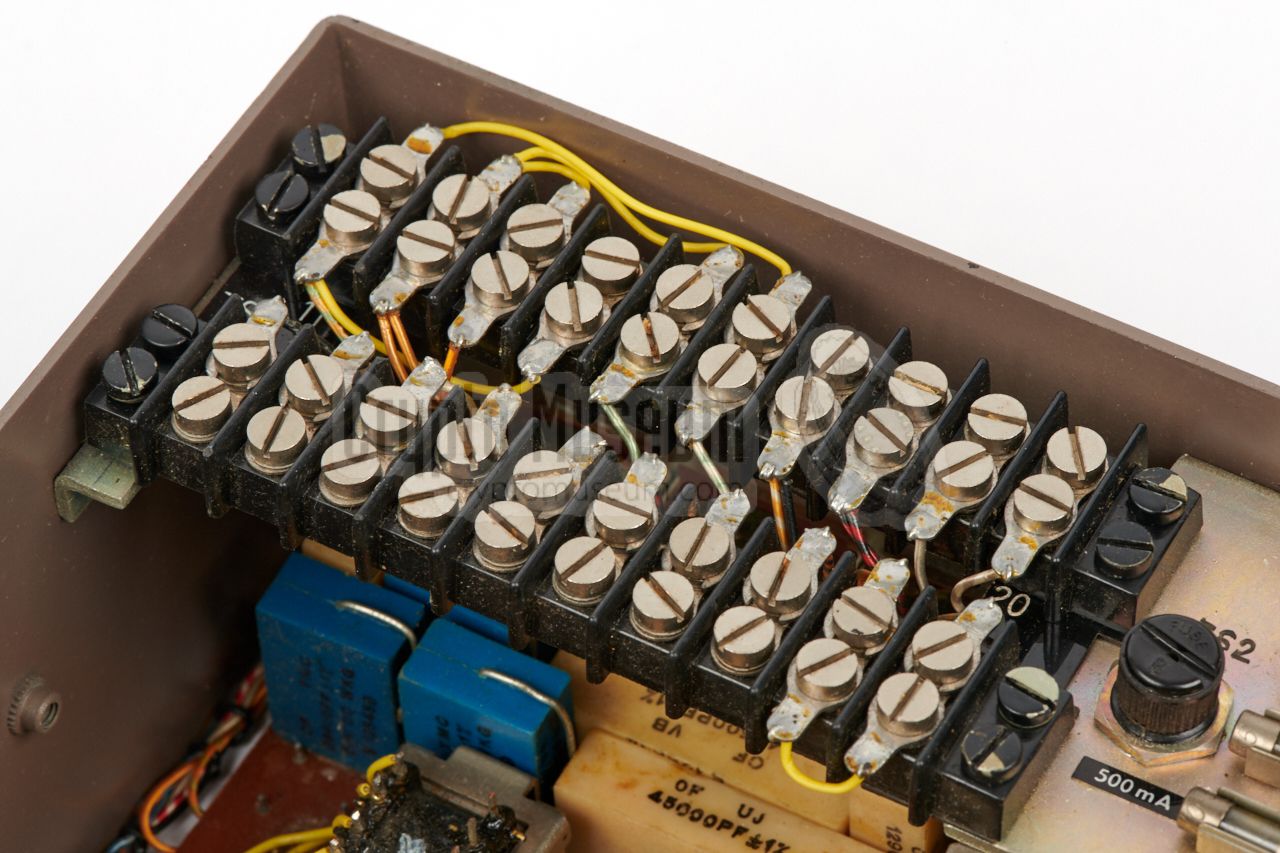
- Improved mains voltage selector (screw terminals instead of solder straps)
- Improved low-pass filters
- Extra notch filter in speaker line (CD2 board)
- 4 spare fuses stowed in the chassis
- 2-wire/2-wire option no longer recommended
- Simplified microphone/line interface board (CD1)
- This production variant: 2000 Hz carrier instead of 2500 Hz
|
|
As the fully transistorised Privacy Sets 8, 8A, 9 and 9A are all nearly
identical, we will restrict the description of the interior to
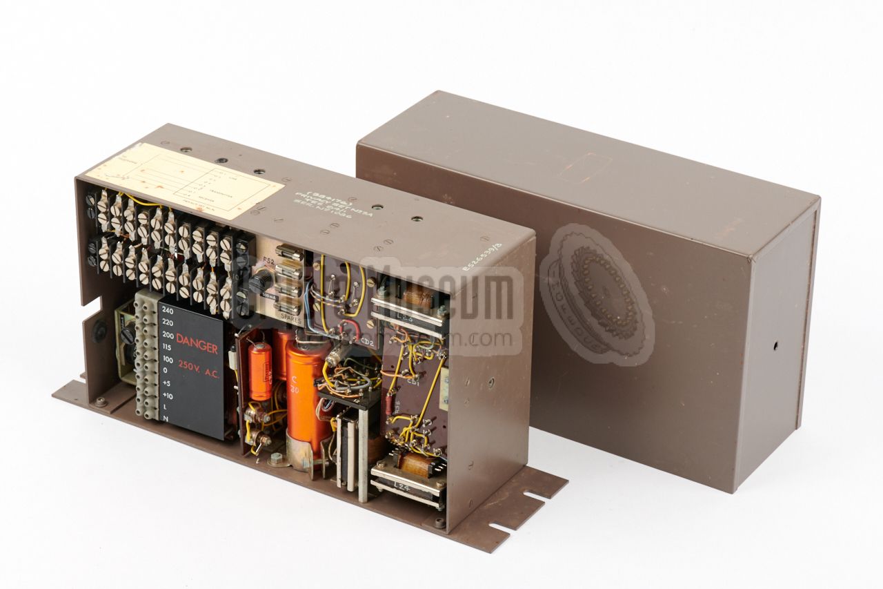
Privacy Set No. 9A, which is shown in the illustration above.
The interior can be accessed
by removing two bolts (one at the front and one at the rear) and
sliding off the metal cover.
This reveals a compact metal frame to which all electronic parts are mounted.
|
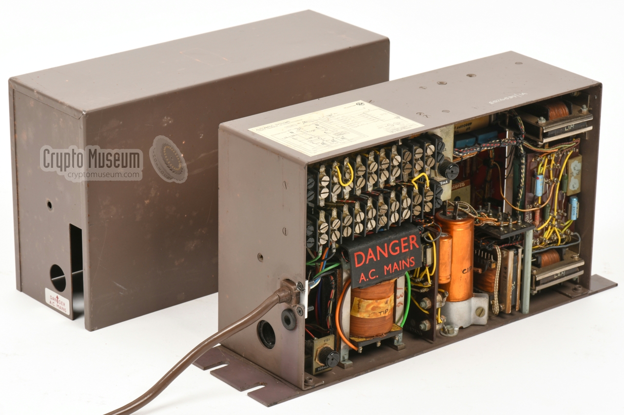
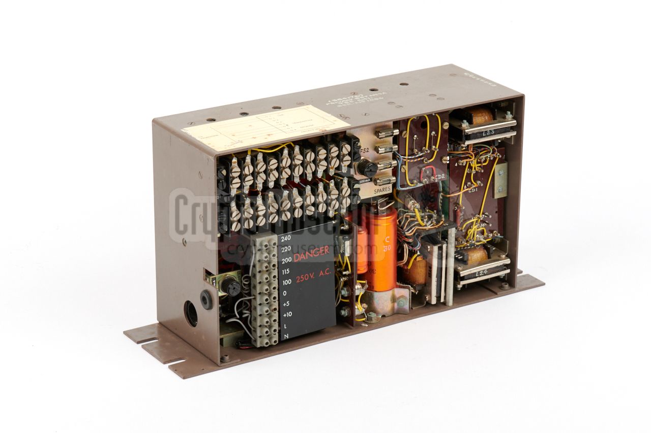
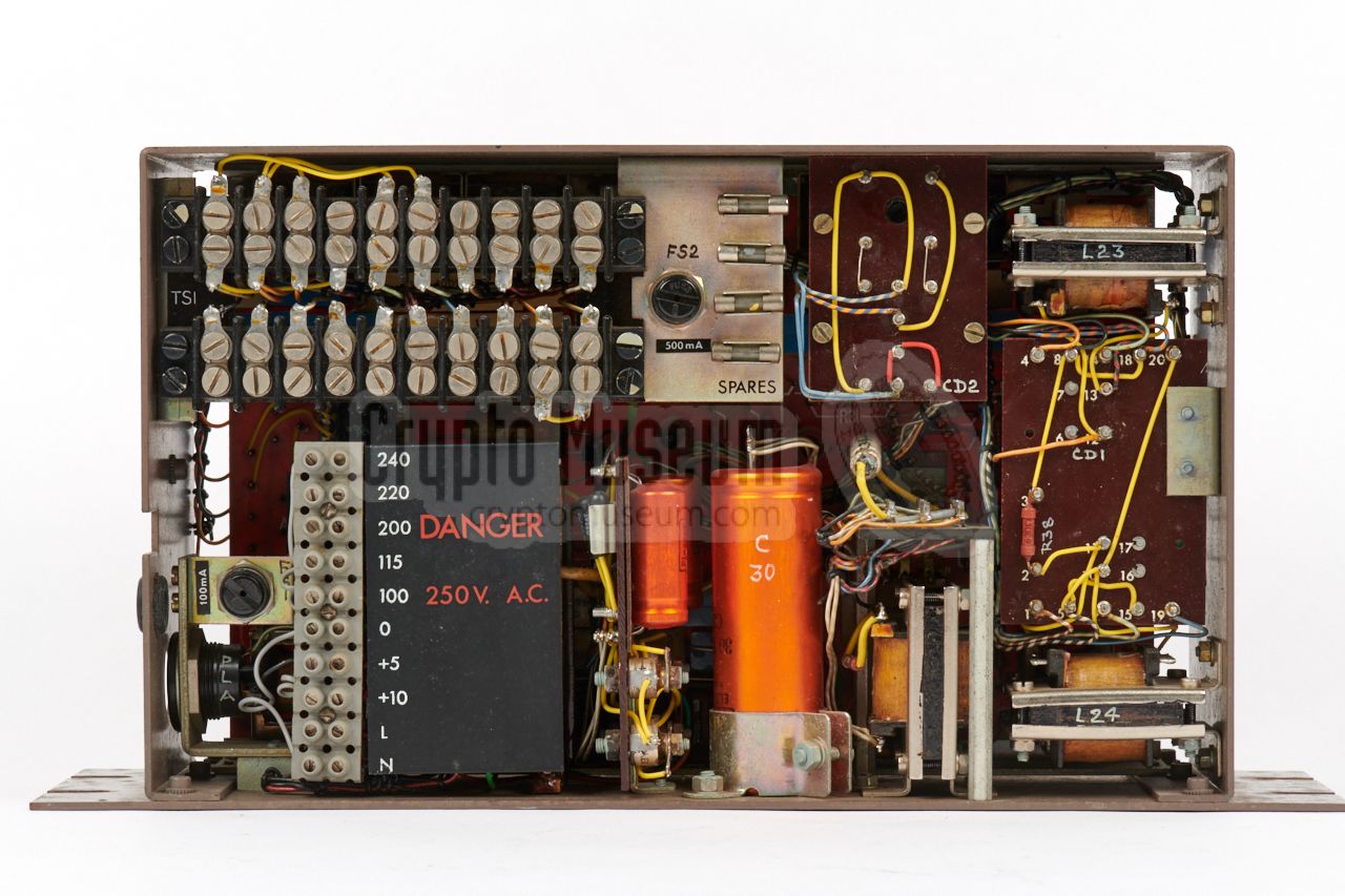
The right side
of the device gives access to the components, with the
power supply unit (PSU) and the
terminal block
immediately visible,
whilst the left side
holds the scrambler board.
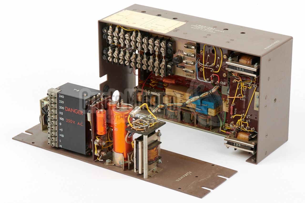
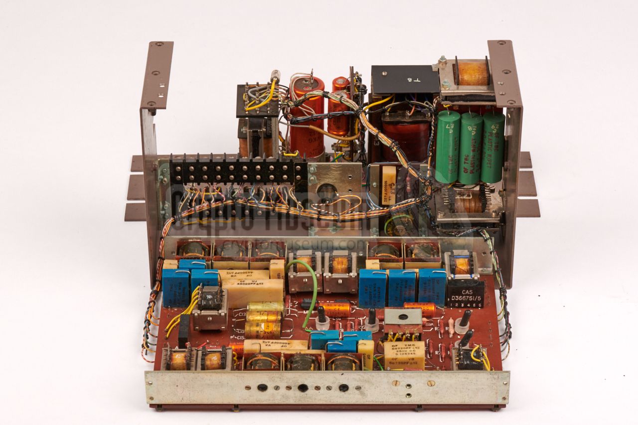
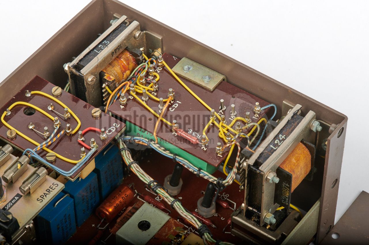
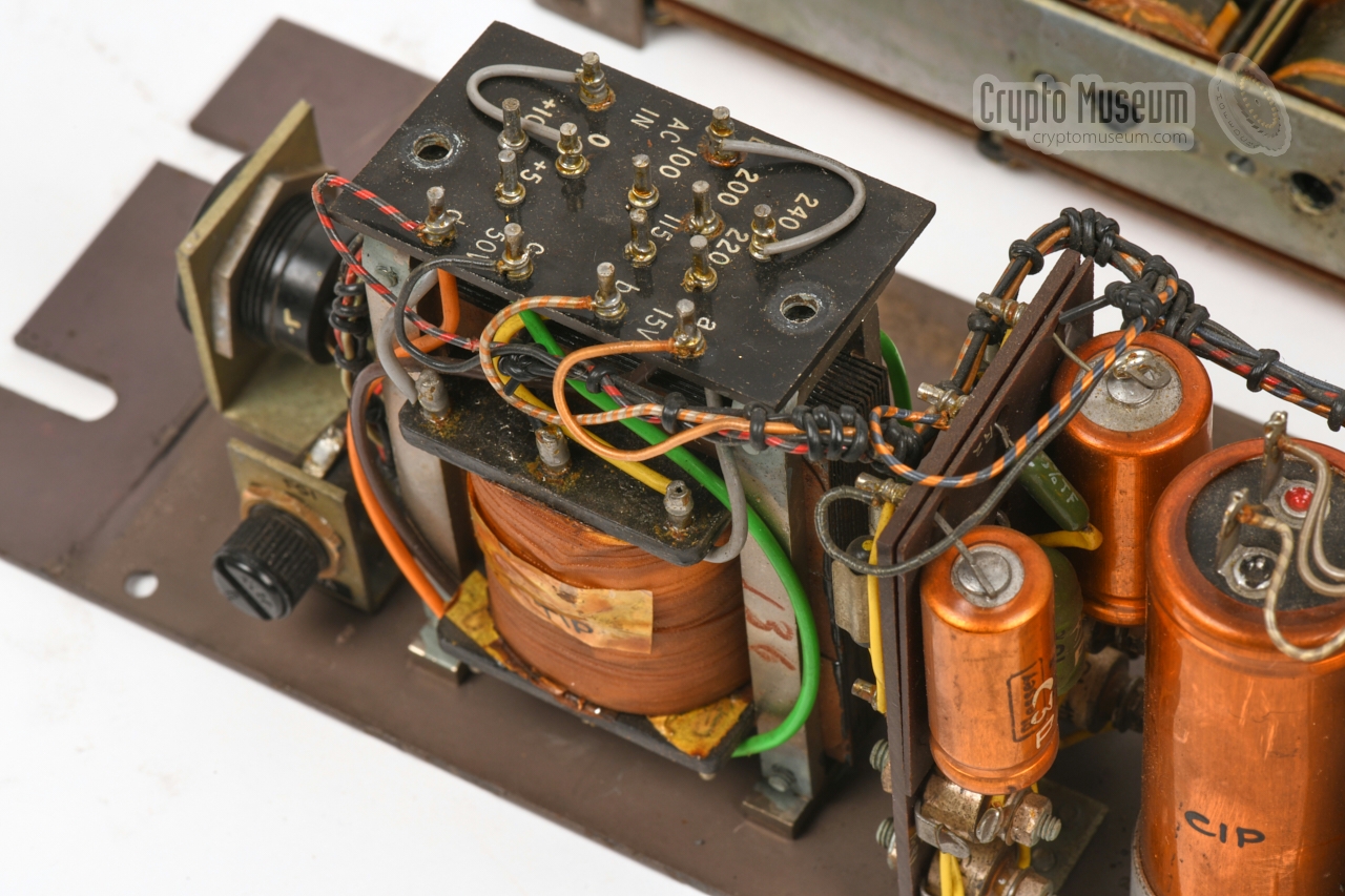
The PSU is mounted to the bottom panel, which is attached to the main frame
by means of six recessed screws at the bottom. After removing these screws,
the PSU can be removed as shown in the image above,
after which the components of the scrambler board
become (partly) visible. In the image on the right, parts of the transmission
section plus the 2500 Hz oscillator are visible.
|
|
|
|
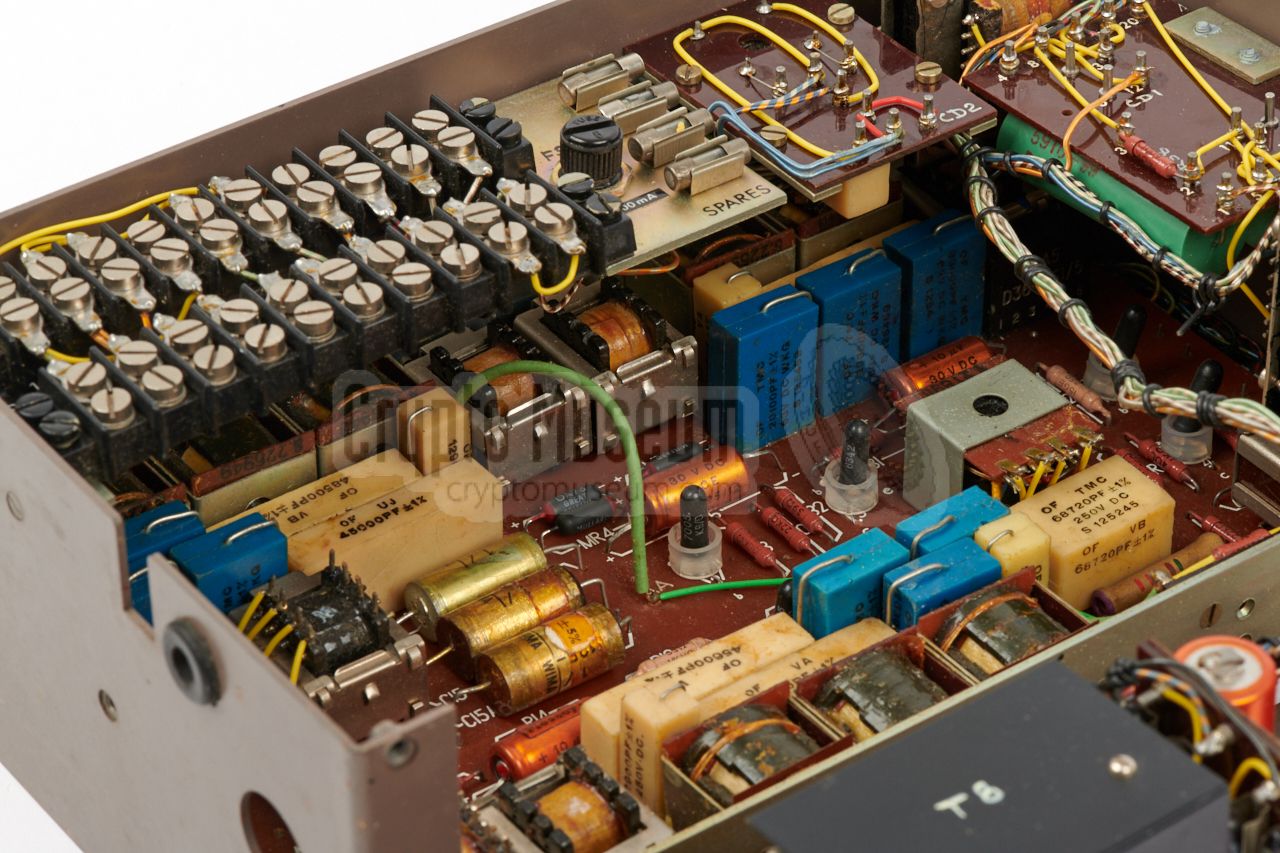
An extra board, mounted to the frame toward the rear, holds a
set of filters.
Depending on the model and version, the PSU is suitable for a single
predetermined mains voltage, or for a range of voltages, including 100V, 115V,
200V, 220V and 240V AC,
as the Privacy Set No. 9A shown here.
|
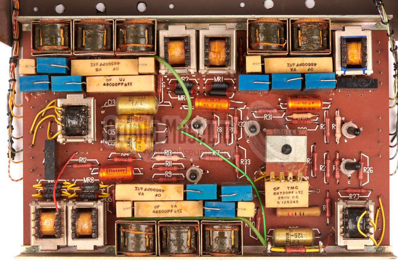
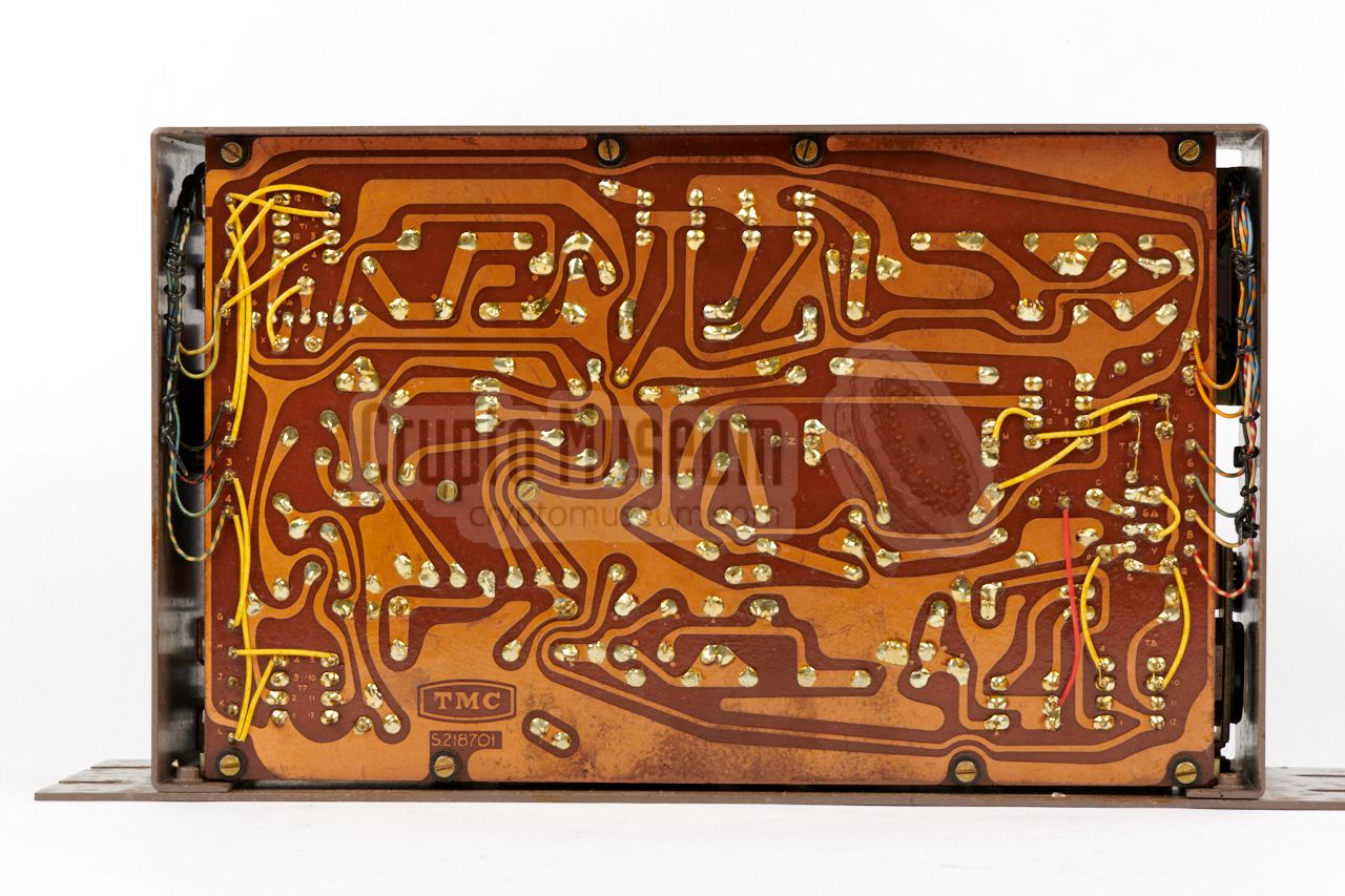
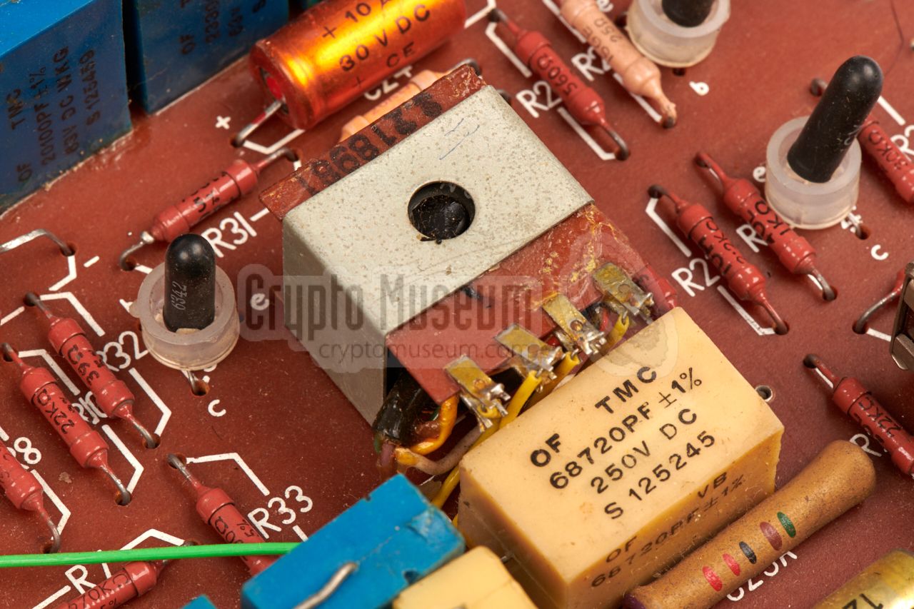
The actual scrambler is located behind the other parts, but can be accessed
from the left side. It is fitted to a metal frame that is mounted
to the case. The image on the right shows the main PCB after it
has been dismounted from the case.
The scrambler is built around just five
CV7005 1 Germanium PNP transistors,
made by Mullard in the UK. According to their date code 2
they were manufactured in late 1963. The rest of the space is
taken by some large transformers, capacitors and inductors. Move the
mouse over the image to reveal the locations of the various blocks.
|
|
|
|
The transmission section is at the upper edge of the image. It is shown
in red. At the far right is the input transformer (TR1). To its left is the
first filter (F1) followed by a mixer,
the second low-pass filter (F2) and an
amplifier (T1 and T2). At the left is the (telephone)
line transformer (TR1).
|
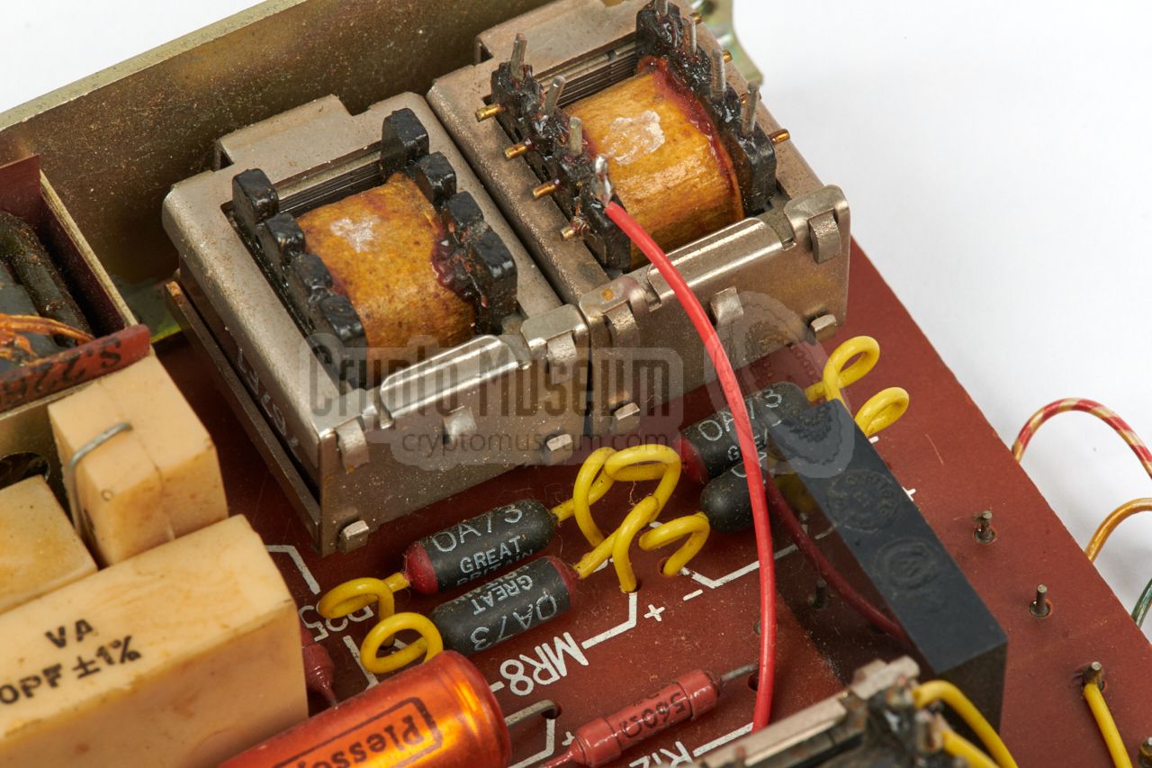
The line transformer is shown in the image on the right, It is fully
balanced and has multiple taps on the primary side, so that it can
be wired to match an impedance of 150Ω, 300Ω or 600Ω.
When using the scrambler on a 2-wire telephone network, this
transformer acts as a fork circuit.
Such lines commonly have a 600Ω impedance.
Along the lower edge is the receiving circuit, in the above image
shown in green. The line signal is first
attenuated
(A2) and then filtered (F3), before it is mixed
with the 2500 Hz signal from the oscillator,
and then amplified (T4 and T5).
|
|
|
|
At the bottom right is the output transformer (TR2) which delivers the signal
to the handset of the telephone. It has multiple taps, so that it can be
adjusted to match the impedance of the speaker in the telephone's handset,
in the same way as the line transformer can be impedance matched.
|
At the centre of the scrambler board — shown in yellow in the above image —
is an oscillator (T3)
which is used by both transmitter and receiver.
It provides the 2500 Hz signal for the two mixers and must be very accurate,
so that it matches that of the scrambler at the other end of the line.
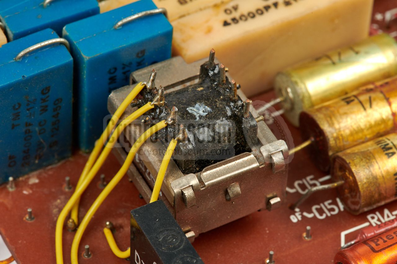
The actual mixing of the audio signal and the 2500 Hz oscillator signal,
is done in a balanced ring mixer that consists of two transformers and
four rectifier diodes. The image on the right shows the mixer of the
receiver circuit, which is identical to the mixer in the transmission circuit.
|
|
|
|
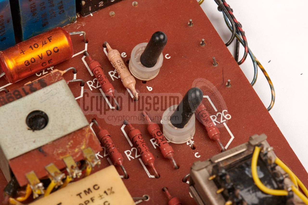
Although the circuit of the scrambler is straightforward, aligning this
device – which is now more than 50 years old – may be difficult. The device
has no potentiometers, but is completely aligned with adjustabe coils.
Furthermore the value of the capacitors and the stability of the old CV7005
germanium transistors – and possibly also the OA73 diodes –
may have deteriorated over time.
|
-
The CV7005 was also made by Philips and is equivalent to the Philips OC71.
-
This is in line with the
marking TES 64/1 at the bottom,
indicating that this model is from 1964.
|
Below is the circuit diagram of the inverter board of the TMC version of
Privacy Set No. 9A as taken down at Crypto Museum in July 2021 from the device
with serial number 1086, batch code TE 64/1 and production code E526539/3.
At the right edge are the connections to the outside
world, numbered as on the PCB. 1 Note that this device has the (+)
side of the power supply connected to ground. If we define ground
as 0V, this means that the unit is powered by -12V DC.
At the top right is the microphone input. The transformer (T1) is suitable for
various impedances. From T1, the signal is fed
through an 11dB attenuator (A1) followed by a low-pass filter, before it is
applied to the balanced ring mixer around T2, T3 and D1-4.
Here the signal is mixed with the fixed carrier from the oscillator around
V3, producing upper and lower sideband signals.
The lower sideband is the mirrored image of the original voice spectrum.
The signal now passes a second low-pass filter — so that only the lower
sideband remains — and is amplified in a two-stage amplifier (V1, V2), before it
is supplied to the subscriber line via the fork circuit (hybrid) T4.
At the bottom is the receiver circuit. From the fork, the signal passes a
6dB attenuator (A2) and is then applied directly to the demodulator, which
consists of a balanced ring mixer around T5, T6 and D5-8. Like in the
transmission path, this produces upper and lower sidebands.
The signal is then fed through a low-pass filter — so that only the lower
sideband remains — and amplified in a two-stage amplifier (V4, V5), before
it is supplied to the handset's speaker, via transformer T7.
|
 |
-
When taking down the circuit diagram of this device, it was not possible
to determine the exact layout and wiring of the hybrid transformer (T4)
without damaging the unit. The wiring of the hybrid (fork) is
therefore an educated guess, based on the design of the
Frequency Changer 6AC.
There are several configuration straps to adapt the unit for 150, 300 or
600Ω impedances. It is shown here in the 600Ω configuration.
|
Below is the circuit diagram of the power supply unit, which consists
of two simple rectifiers with stabilisation circuits, but without
a transistor-based regulator. As a result, the voltage on the -12V
rail may vary slightly, resulting in a less stable carrier signal
from the oscillator.
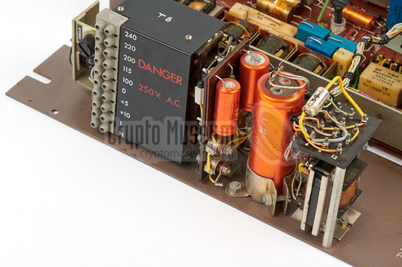
The mains transformer (T8) can be configured for virtually any mains
AC voltage, by means of solder straps ast its top. T8 has two
secondary windings: 15V AC for the -12V DC supply of the inverter
board, and 50V AC for the 15 mA current source that provides the
bias for the carbon microphone of the connected handset, and
the line current in a 2-wire/2-wire configuration.
|
|
The table below gives the pinout of the screw terminal block inside
Privacy Set 8/8A
and 9/9A. This is the lowest row of screws when looking at
the device from the right side. The first column shows the colours, whilst the
second one specified the contact number inside the BT20/8 box.
|
Green BT3 Line B 1 Black BT6 Line A 2 unused Audio in 2 unused Audio in 2 White BT4 Microphone Red BT1 Microphone 3 Blue BT1 Speaker 3 Orange BT5 Speaker Loop wired to 10 Loop wired to 9
|
|
-
In 2-wire configuration the line is connected here.
In 4-wire configuration, this is the Audio out line.
-
Used in 4-wire configuration (e.g. when connected to a radio).
-
Lines (6) and (7) are joined in the connection box (at point BT1).
|
Below is the internal wiring diagram of the
SA 5030 and similar voice terminals.
At the bottom right are the (A) and (B) terminals of the subscriber line.
Directly above it, is the wiring to the terminal block of the Privacy
Set No. 8. The make-before-break (MBB) switches KA (1-4) are part of
the 303/A Key Unit
that is controlled by the 2 (or 3) push-buttons on top of the
voice terminal.
They allow the telephone set to be used for plain as well as secure
calls. In secure mode, the speaker and microphone of the telephone's
Handset No. 164
are routed via the Privacy Set.
The above circuit diagram is for the SA-50xx voice terminals of
WWII, but is also applicable to the post-war modified GPO
Telephone Set No. 710 and 740 units. During the war, the dial
was often omitted from the telephone set — most exchanges were
manually patched — but in the 1960s and 70s most exhanges were
automatically switched. In addition, most wartime installations
were of the Local Battery type (LB), whilst the post-war systems
were generally Central Battery (CB).
|
To allow the Privacy Set and suitable telephone sets to be tested, used
and demonstrated in various configurations, without altering the fragile
vintage wiring of the devices all the time, Crypto Museum has defined its own
standard, involving inline 7-pin male/female
XLR connectors.
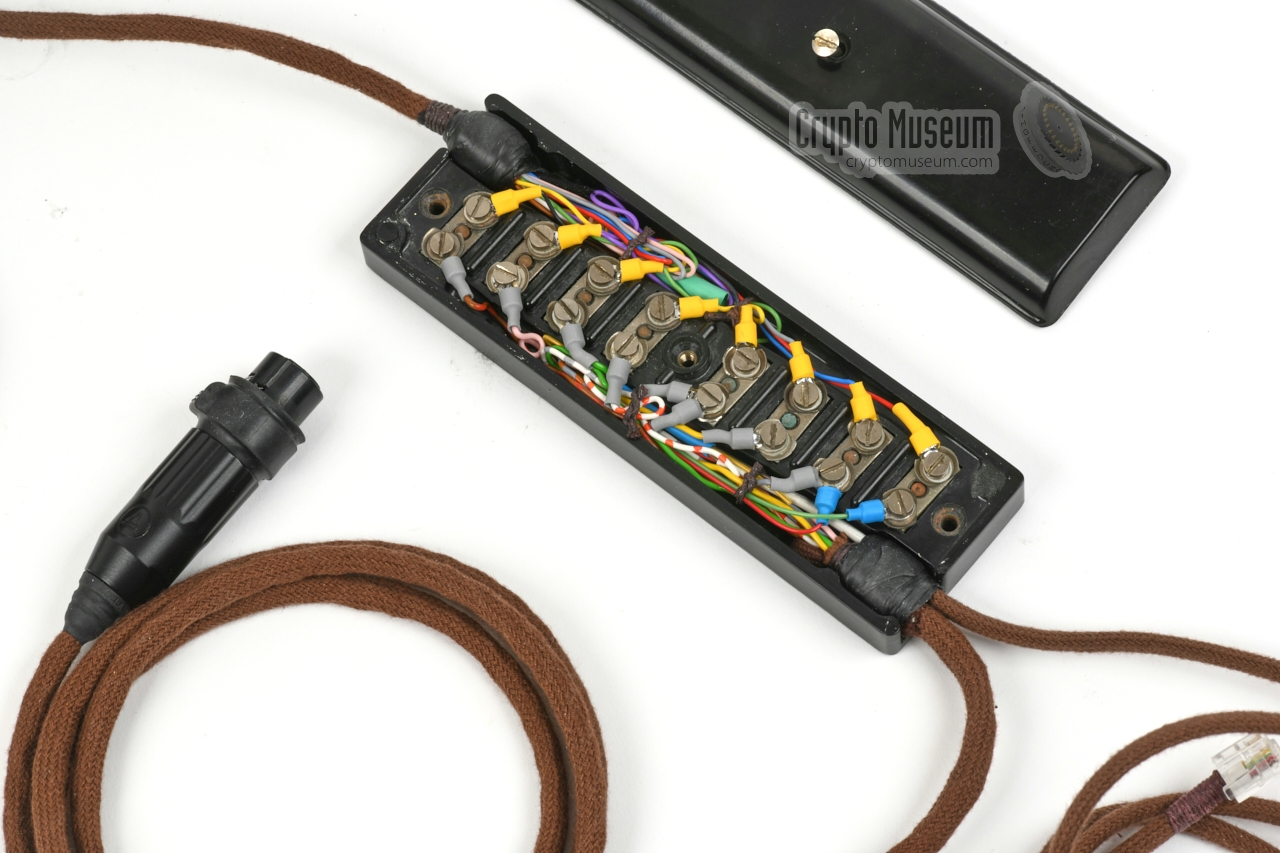
In this standard, an 8-point junction box BT 20/8 is used as the
central hub. The SA 50xx voice terminal is fitted to the BT 20/8 via
a fixed 8-wire braided cable. The subscriber line is also fitted to the
BT 20/8 via a fixed 2-wire or 4-wire braided cable, whilst a fixed
7-wire braided cable with an XLR7/F connector
at the end is present for quick (dis)connection of the Frequency Changer.
The Privacy Set itself is fitted with a fixed 7 or 8-wire brown PVC cable
with an XLR7/M connector at the end. This allows the Privacy Set
to be disconnected from the setup without opening it and unscrewing the
wires from its terminal block or from the
BT 20/8 box.
Below is the pinout of the XLR7/M connector that is fitted to the end of the
fixed cable of the Privacy Set. The wiring order is identical to the
order on the terminal block inside the
predecessor: Frequency Changer 6AC.
|
Line (B) green Line (A) black - LB (or unused)
Microphone (H) white Microphone (L) red Speaker (L) blue Speaker (H) orange
|
|
Type Voice scrambler Principle Single frequency inversion Manufacturer TMC Batch code TES 64/1 Product code E526539/3 Carrier 2000 Hz 1 Impedance Standard telephone line at 150, 300 or 600Ω Terminal Modified conventional analogue telephone set Dimensions 255 × 155 × 90 mm (305 × 155 × 90 mm with mounting flanges) Weight 4520 grams
|
-
Note that this praticular production variant of Privacy Set No. 9A,
uses an inversion frequency of 2000 Hz rather than the more common
2500 Hz. As a result, it is incompatible with the 2500 Hz variants.
|
|
|
|
Any links shown in red are currently unavailable.
If you like the information on this website, why not make a donation?
© Crypto Museum. Created: Wednesday 26 May 2021. Last changed: Tuesday, 10 August 2021 - 18:42 CET.
|
|

|
|
|


![Block diagram of Privacy Set No. 8. Click to see the original drawing [1].](files/ps_block.jpg)


