|
|
|
|
|

|
|
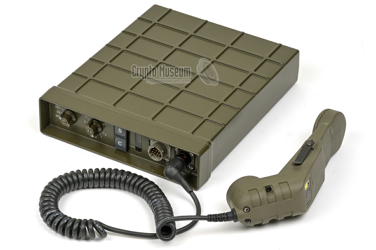
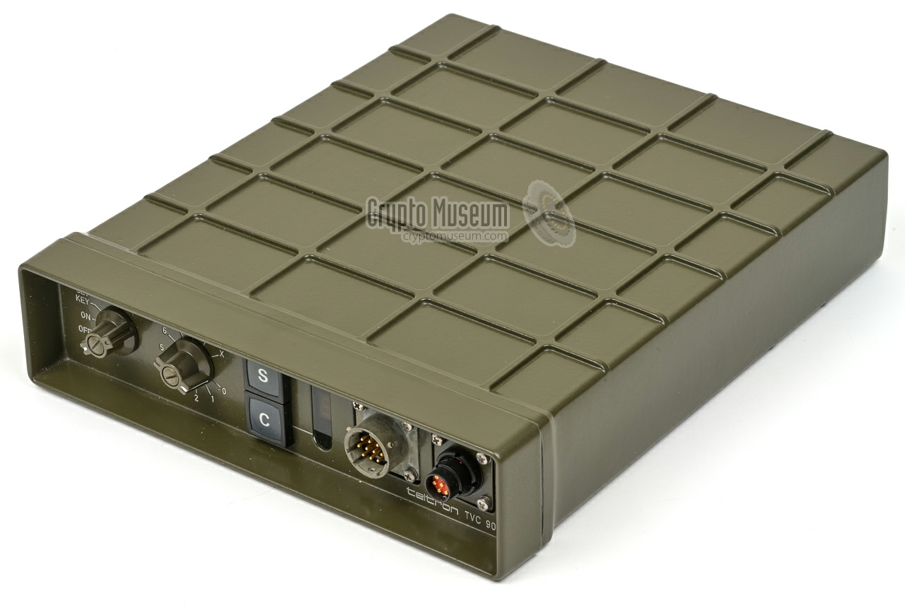
Teltron F/T Scambler
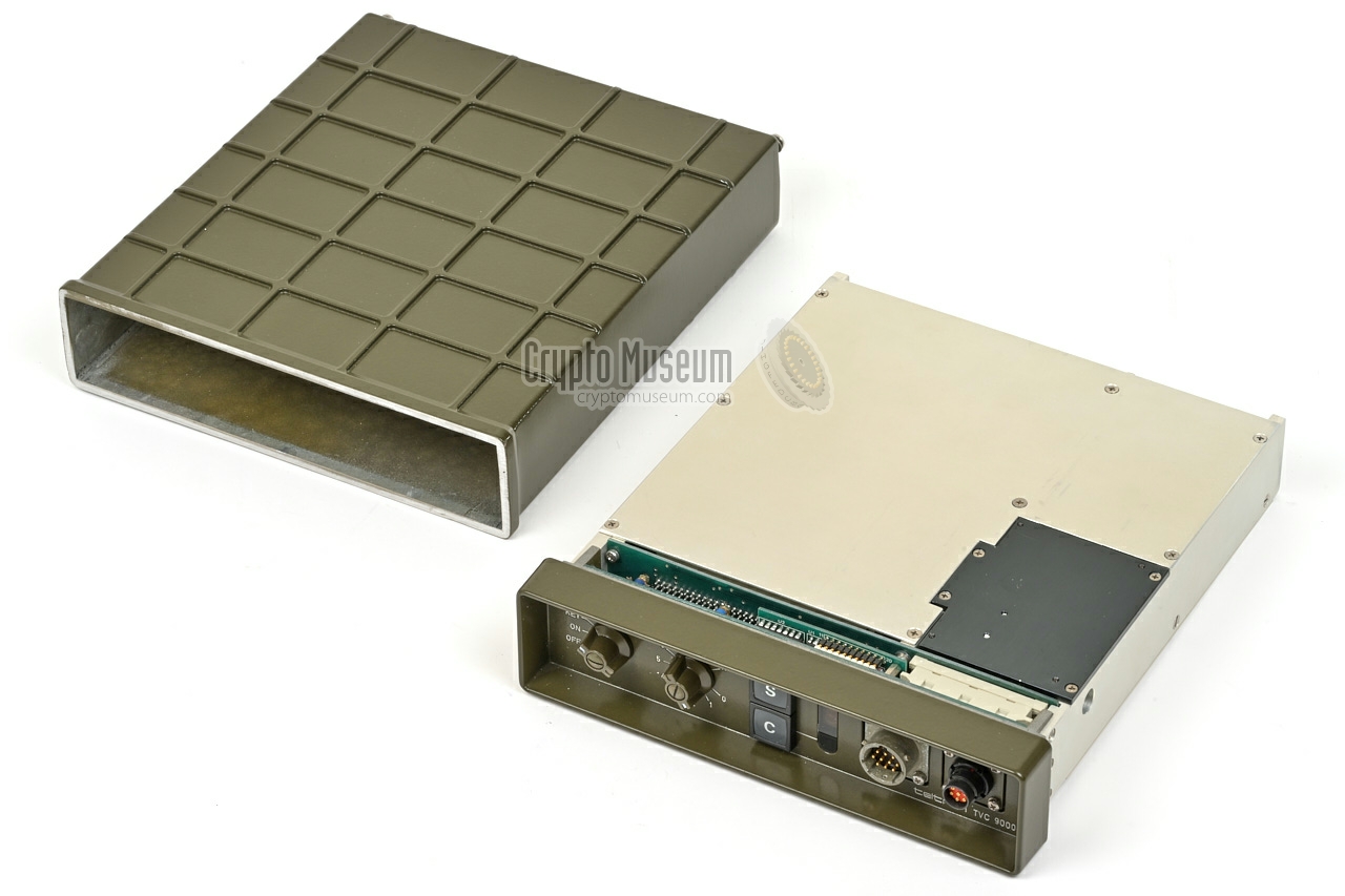
It is housed in a green military grade die-cast aluminium
enclosure that measures 252 × 213 × 51 mm and weighs 2.4 kg.
It consists of a front panel and a case shell. All internal parts
are mounted to the front panel.
Strangely, the device shown here does not have a serial number.
It might have been sold as an OEM product.
The TVC-9000 is suitable for scrambled transmission via HF/SSB,
VHF and UHF radio channels. The duplex version was also suitable
for use on fixed analogue telephone circuits (POTS) and analogue mobile
cellular phones (car phones).
|
|
|
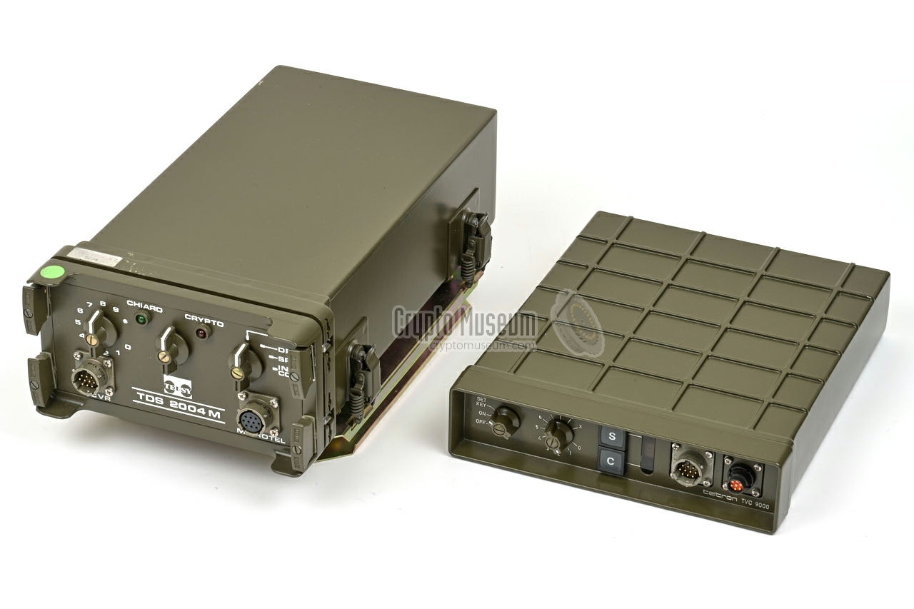
The device was introduced in 1984 as a replacement for the rebatched
Telsy TDS-2004M, which had been sold by
Teltron
until that moment as the TVC-9000. The newly developed device was
announced as a replacement. It had been developed secretly outside
the view of supplier Telsy, and was
basically a clone
for which the intellectual property (IP) had been
stolen from Telsy.
TVC-9000 was also sold as an OEM product by ANT 1
as ANTSEC-2001.
It is known that a batch of ~50 new TVC-9000 units was sold to
an unspecified African country [4].
The fact that Teltron was able to obtain an export
licence for the device, raises the suspicion that the German
authorities (BND, ZfCh) were able to break the encryption [5].
The TVC-9000 was in production until Teltron's demise
in late 1988. The one shown here was probably made in the first half
of 1988. 2
|
-
At the time (1984) ANT was owned by
AEG Telefunken.
-
Based on date codes on the components.
|
The image below gives an overview of the controls and connections
of the TVC-9000, al of which are located at the front panel.
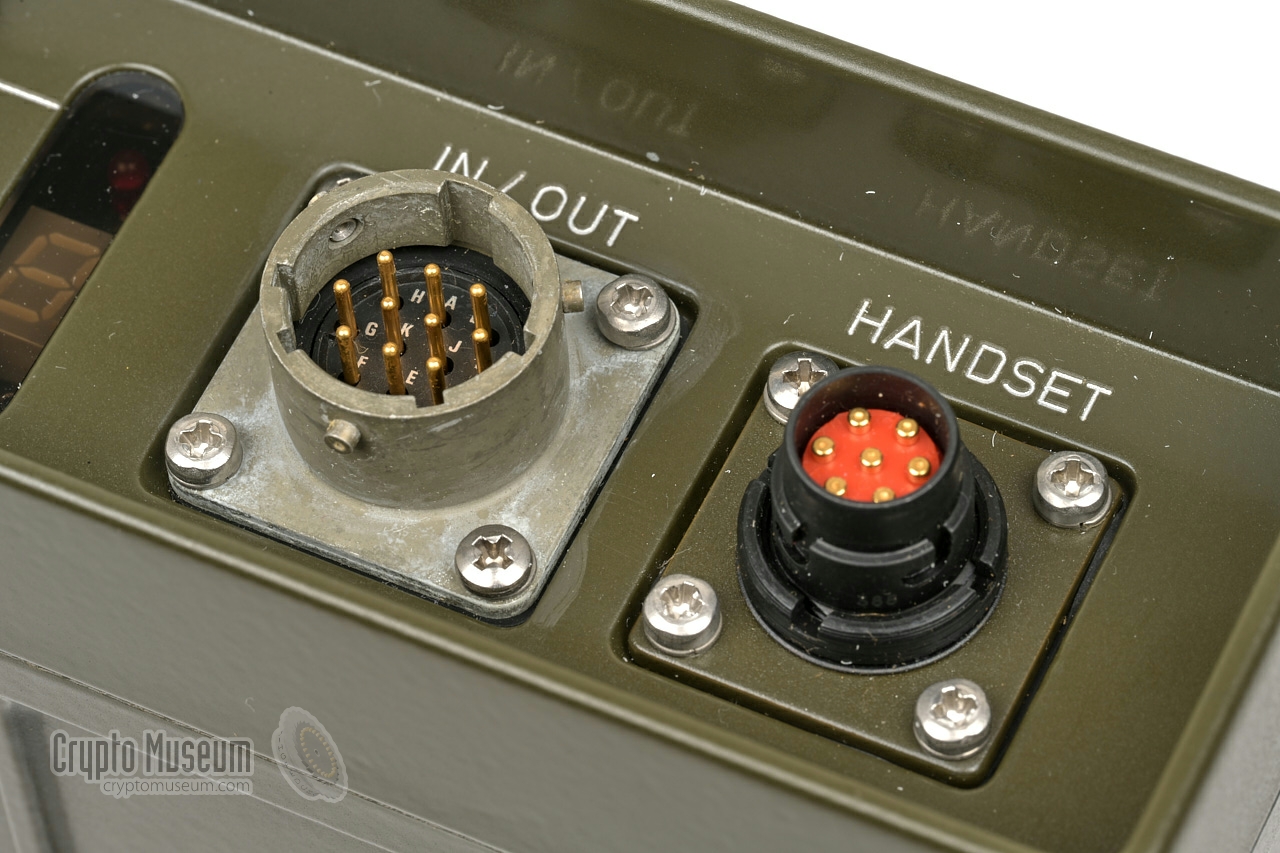
The IN/OUT connector holds the wiring to the connected radio
or (analogue) mobile telephone, and a 12V DC power source such
as the battery of a vehicle. To its right is an
NF7 connector for the handset,
that is wired according to the German standard.
At the far left is the MODE selector. It is used to turn the device
ON or OFF, or to enter a new cryptographic key (SET KEY). When in the
SET KEY mode, the rotary selector to its right must be used to enter
the desired key.
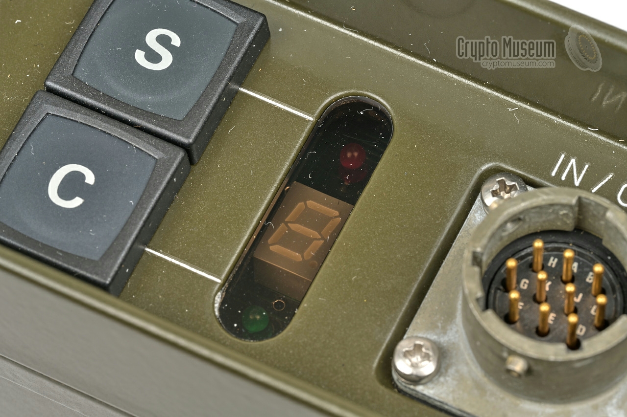
At the centre are two push-buttons: one to select secure mode (S)
and one to select clear mode (C). To their right is a single 7-segment
display plus two LEDs that show the current status.
The buttons and the LEDs are also used in the SET KEY-mode.
|
- Telsy version
This is the original version of the TVC-9000. It was developed and
manufactured by Telsy in Italy as the
TDS-2004M and rebatched by Teltron.
Around 1984, it was replaced
by the interoperable TVC-9000 that was made by Teltron itself.
➤ Original Telsy TDS-2004M
- Teltron TVC-9000 Rev. 1
This is the initial 1984 release of Teltron's own version of the TVC-9000.
It is similar to the device shown here, although the layout of the front
panel is slightly different. The IN/OUT socket is at the far right,
whilst the HANDSET socket is at the far left. Furthermore, the HANDSET
socket is of the same 10-pin military type as on the
Telsy TDS-2004M.
It was resold as an OEM product by
ANT as the
ANTSEC 2001 [6].
- Teltron TVC-9000 Rev. 2 simplex version
With this version, both connectors are at the far right, although the
HANDSET socket is of the German NF7 type.
The simplex version of the device is suitable for any type of 2-way radio,
including (military) HF, VHF and UHF simplex radio sets.
With this version, the analogue board is
not fully populated, and the
scrambler circuit alternates between the transmission and reception
path. In this case the push-to-talk (PTT) in the handset must be used
to switch from receive to transmit. The device features here
is of this type.
- Teltron TVC-9000 Rev. 2 duplex version
This is the same device, but with a fully populated analogue board.
In this case, the scrambler has two separate circuits: one for the
transmission path and one for the reception path. It allows the
device to be used in full duplex telephone circuits, such as the POTS
and analogue mobile phone systems (car phones).
- Teltron TVC-9001
This is the rackmount version of the TVC-9000.
|
|
|
ANTSEC 2004
|
|
In the early days of its existence, around 1972,
Teltron developed its own voice scramblers,
such as the SP-601, which were based on single-frequency
spectrum inversion. In the early 1980s, the company started selling its
TVC-9000 series of two-dimensional scramblers, which were actually OEM
products made by the Italian company Telsy.
This resulted in products like the TVC-9003 and TVC-9004. In 1983,
Teltron decided to develop its own products again
and allegedly copied Telsy's designs and started
the production of the cloned devices [2].
Around 1984, this resulted in the in-house produced TVC-9000,
which is basically a clone of Telsy's TDS-2004M.
It which was reportedly the most secure two-dimensional scrambler for car phones
at the time [3]. A batch of at least 50 units was sold to an African country
[4], probably through the German manufacturer ANT,
a subsidiary of AEG Telefunken. At the time,
ANT sold the rebatched TVC-9000 as its ANTSEC-2001 [6][7].
The theft of intellectual property damaged
the relationship with former partner Telsy.
It prompted Telsy to copy-protect its later designs.
|
|
The TVC-9000 has nine key compartments, numbered 1-9, selectable with
a rotary selector at the front panel.
Set the MODE selector to 'ON'.
Then select the desired key compartment with the rotary (1-9).
Key selection '0' is reserved for PRIVATE operation.
It offers low-security full-duplex conversations, but
is not available on the simplex version of the device.
'X' should be selected when an external remote control
unit (RCU) is used, in which the key is selected on the RCU.
|
Each key compartment can hold a cryptographic key with a length of up to
8 decimal digits. This means that any number between 0 and 99.999.999 can
be used. All keys are equally secure, even if they have less digits.
The keys are held in the device's non-volatile 2KB CMOS RAM,
and will be retained for several
months by the built-in rechargeable backup battery.
Note tat the first digit of the key determines the security mode:
|
1-5 Time domain scrambling (one-dimensonal) 6-9 Frequency and time domain scrambling (two-dimensional)
|
|
To program a key into one of the key compartments, do the following:
|
- Set the MODE selector to 'SET KEY'.
The green CLEAR LED (under the display) will now blink. - Next, select the desired key compartment with the rotary (1-9).
The display shows the selected compartment (1-9).
A blinking display indicates that the key compartment is currently empty. - Press 'C' to clear the contents of the selected compartment.
- Select the first digit of the key with the rotary.
Remember that this digit also determines the security mode. - Press 'S' to set the first digit of the key.
- Select the next digit of the key and press 'S'.
- Repeat the previous step until all digits of the key have been entered.
- Set the MODE selector to 'ON'.
The device is now ready for operation.
|
|
If a mistake is made when entering the key, the red LED (above
the display) will blink. In that case repeat the above procedure and
do not forget to clear the compartment first (point 3).
|
|
In case of an emergency, all keys can be purged instantly, by doing the
following:
|
- Set the rotary to 'X'.
- Set the MODE selector to 'SET KEY'.
The display now shows ≡. If the display blinks, the keys have already been erased. - Press 'C'. All keys have now been destroyed.
|
To operate the device, turn it on by setting the MODE selector to 'ON'.
Ensure that valid keys are programmed into one or more key compartments,
using the procedure described above. Select the desired key compartment
with the rotary, and press 'S' to confirm. The device is now in SECURE
mode (crypto). To return to CLEAR mode, press 'C'.
|
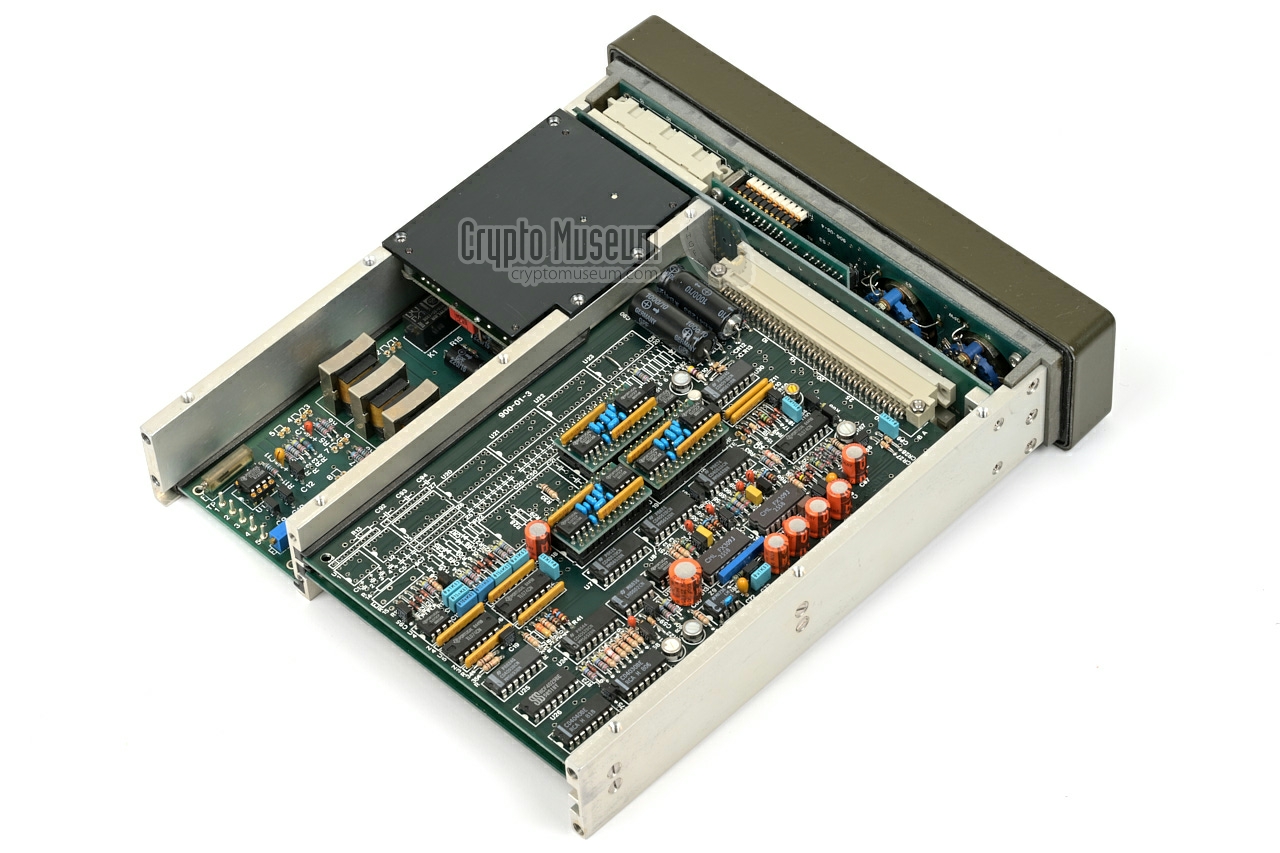
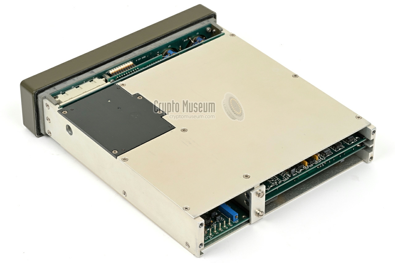
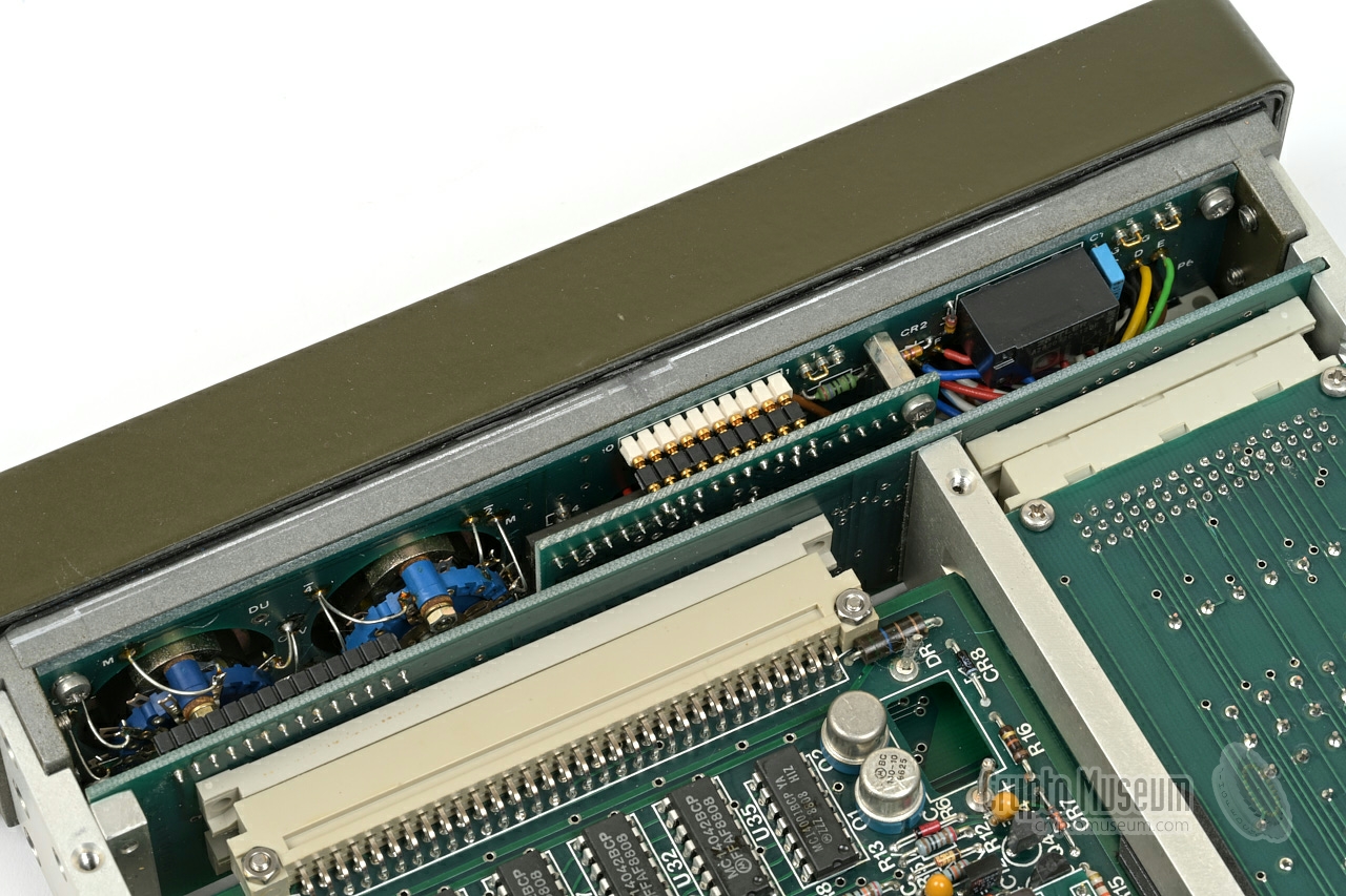
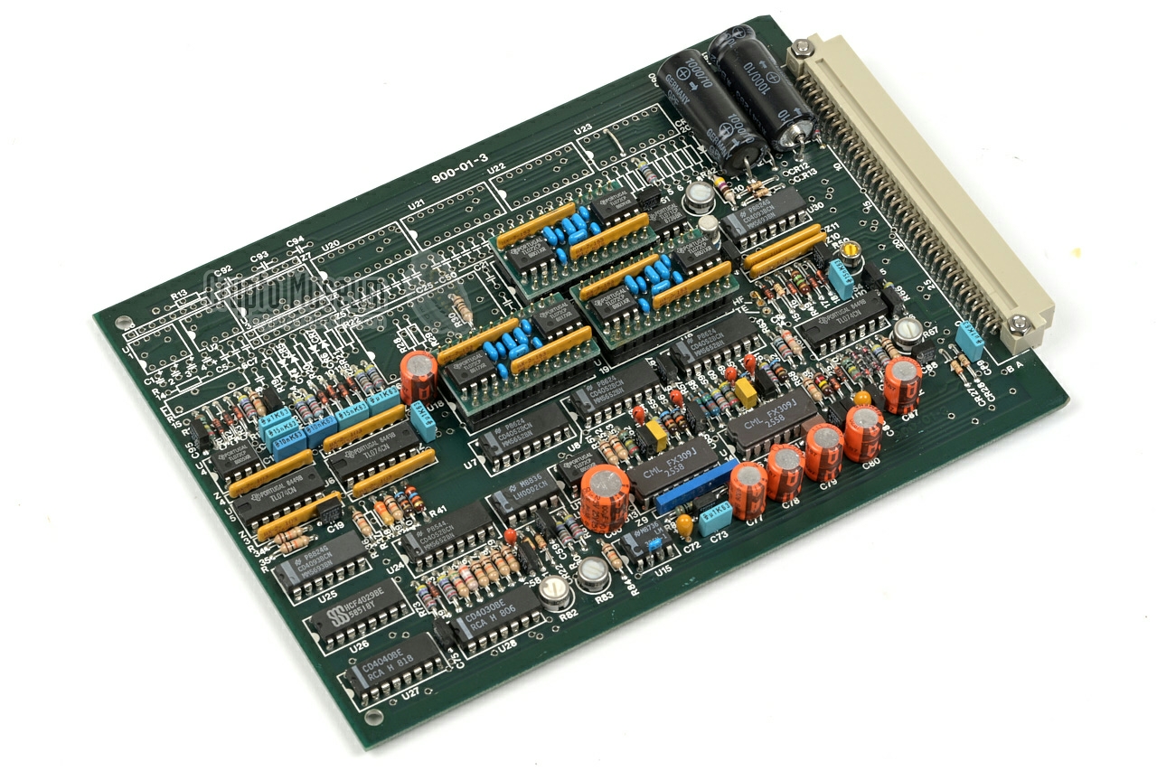
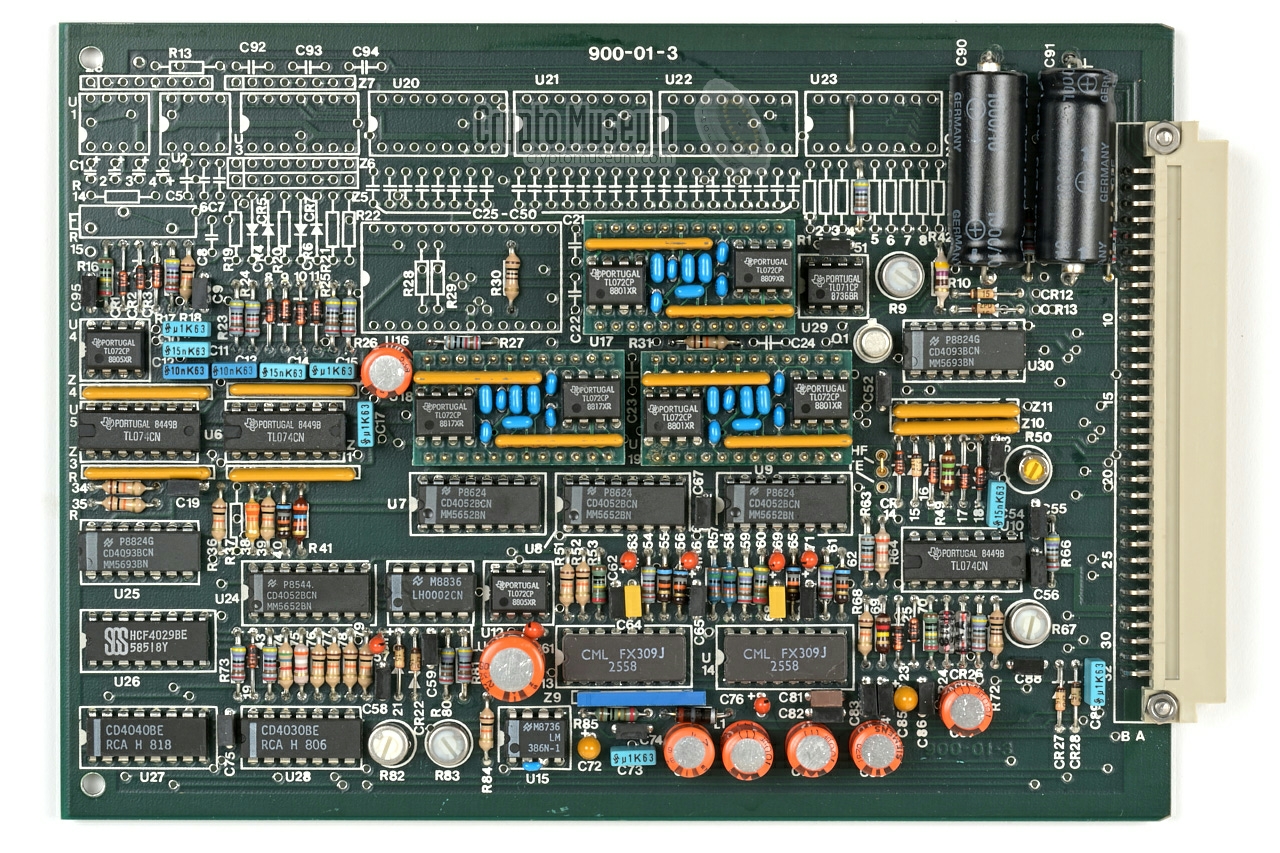
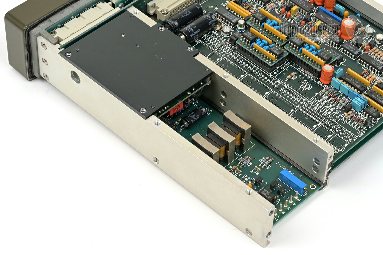
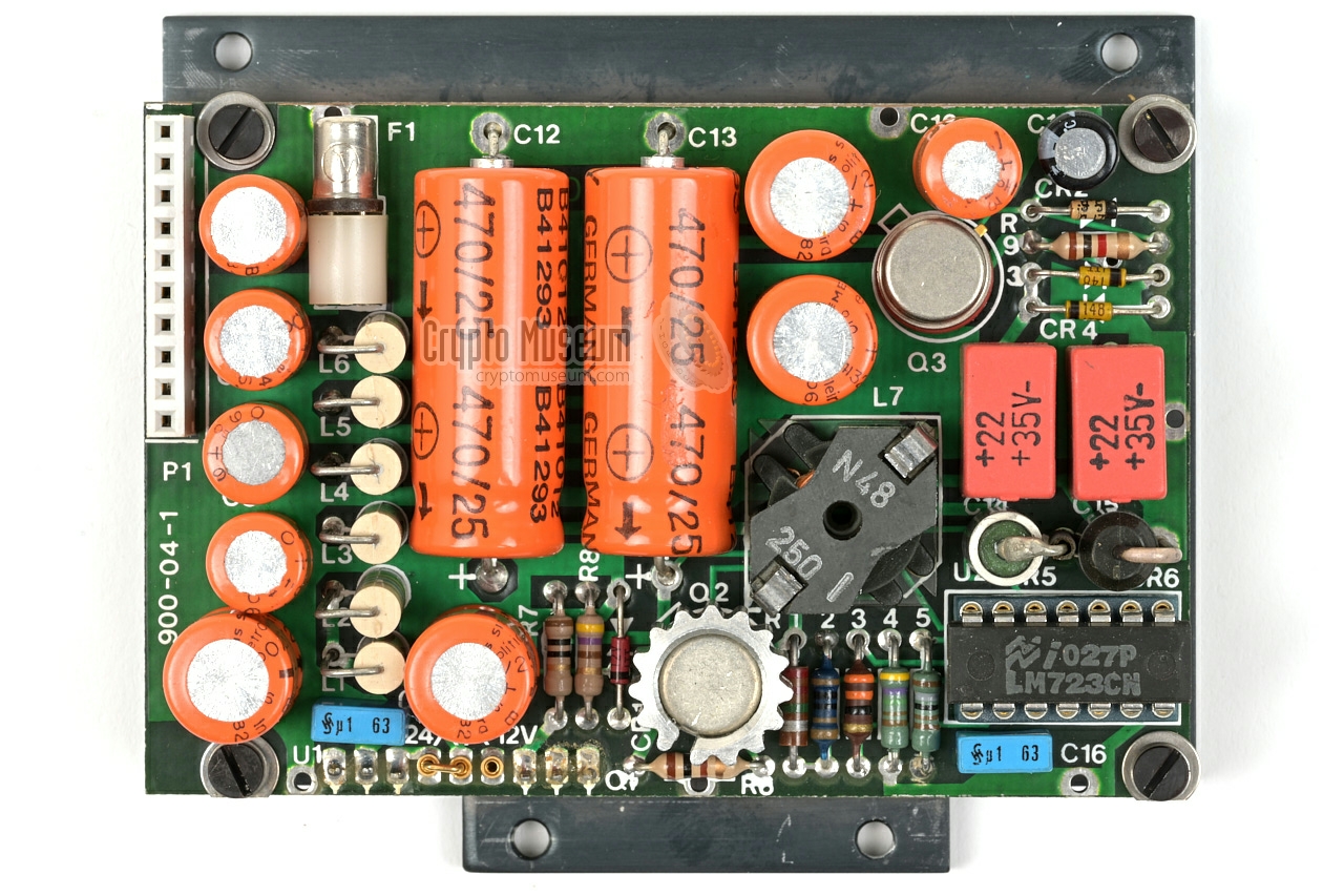
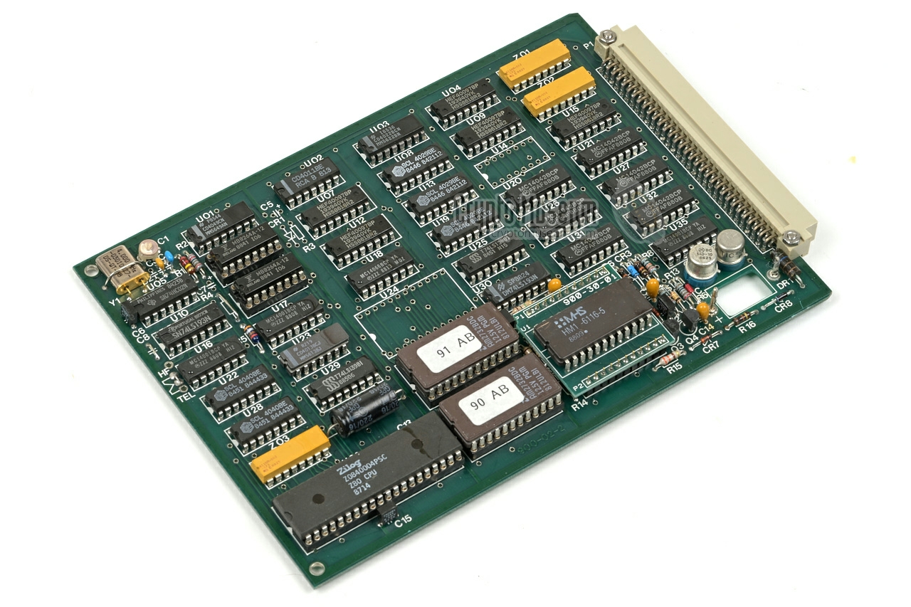
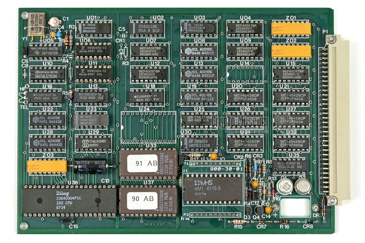
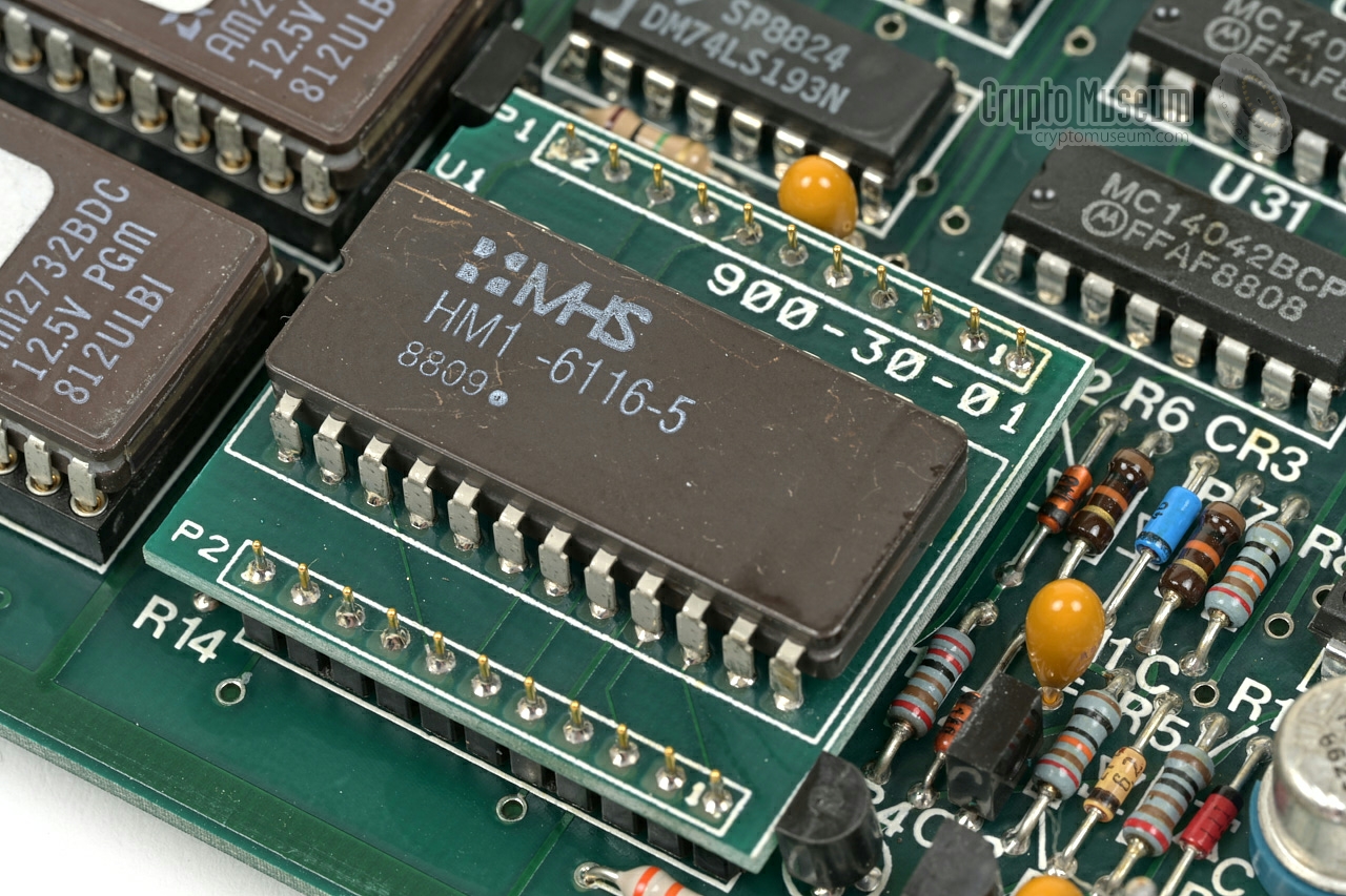
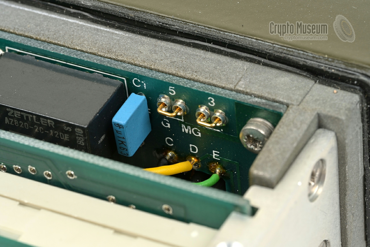
The interior of the device can be accessed by loosening four screws
at the rear, after which the
case shell can be removed. This reveals
the interior as shown in the image below. Inside the device are
seven PCBs, six of which are visible in the image. Immediately behind
the front panel is a PCB that holds the controls and connectors.
It has a small daughter board that holds the display electronics.
The front panel and all other boards are plugged into the
full-width backplane.
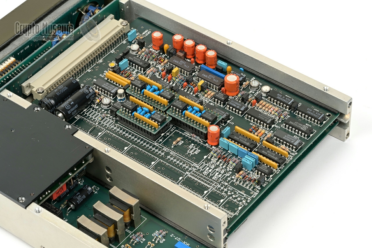
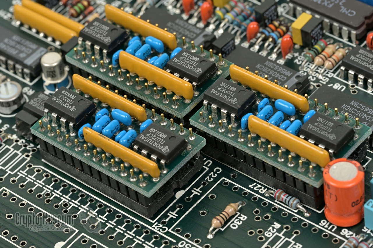
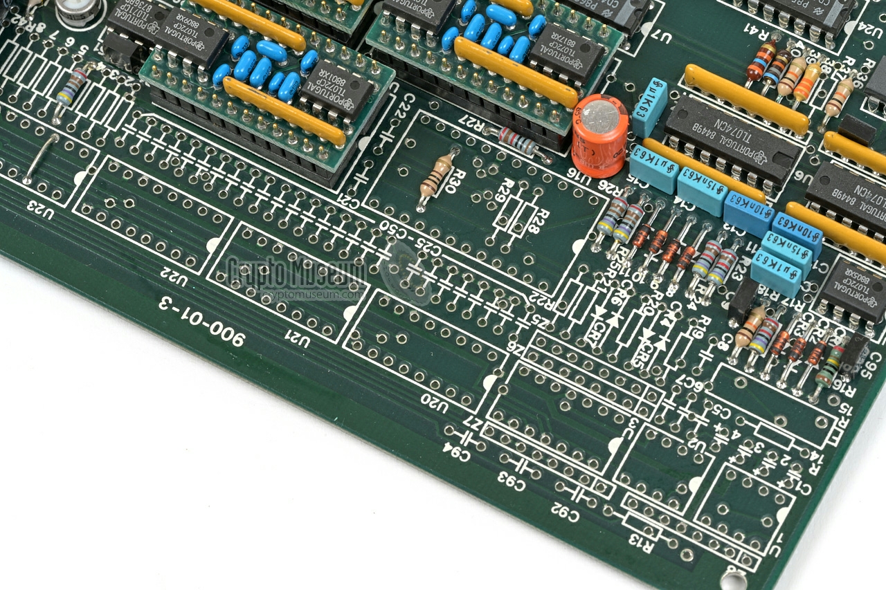
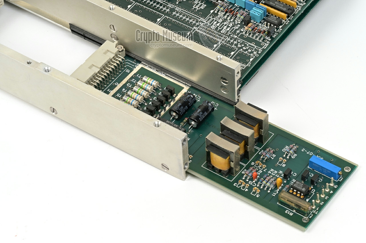
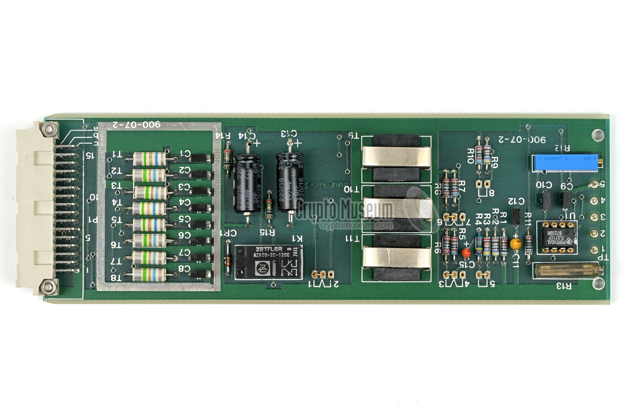
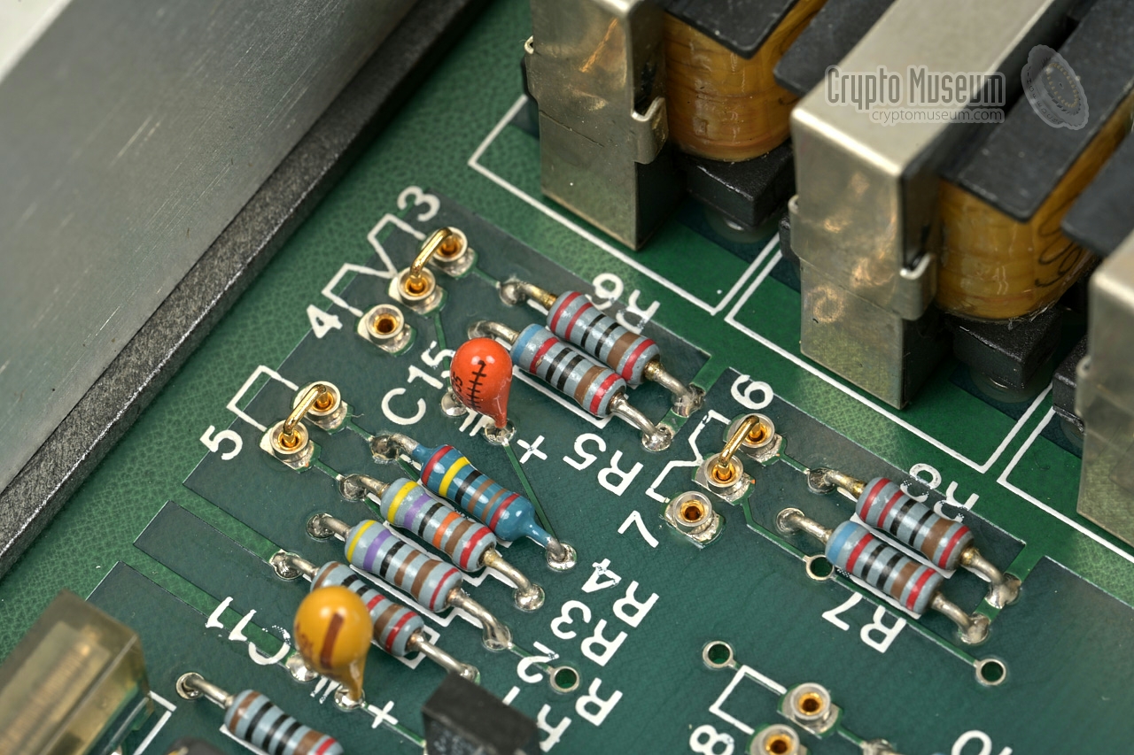
The largest PCB is the analogue board.
It holds the audio circuits and the actual scrambler. At the centre
of this board are three identical plug-in boards.
These are the active filters that replace
the custom TY252x hybrid modules of the
original Telsy design.
The rest of the design is very similar to the Telsy design.
At the right are the two
FX309 CVSD (de)modulators
made by Consumer Microcircuits in the UK. To the left of the
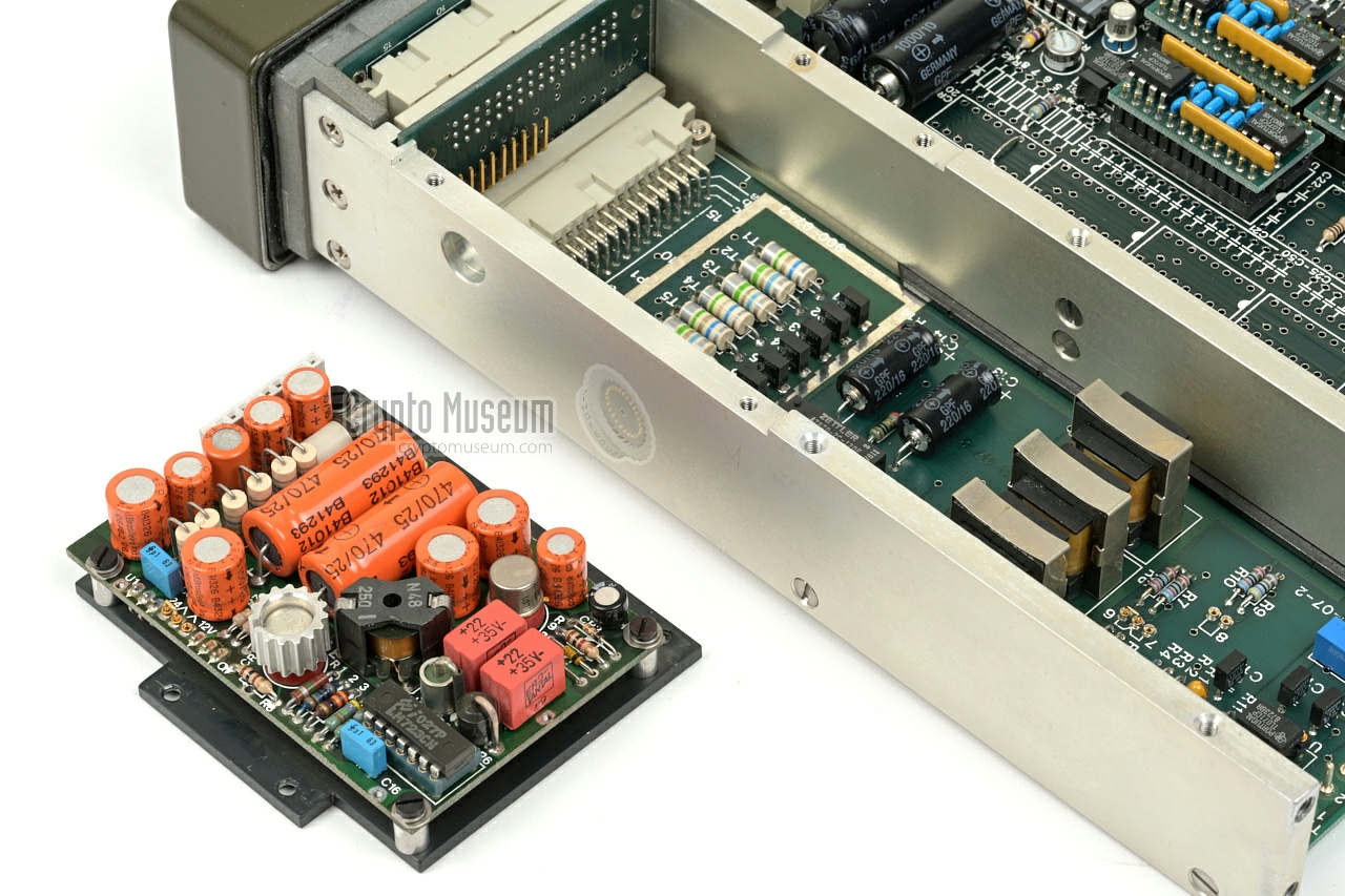
analogue board is a narrow board that
holds the audio filters. The black part above it, is the back side
of the switched mode power supply unit (PSU).
It is responsible for the conversion
of the external 11-15V to the necessary internal voltages.
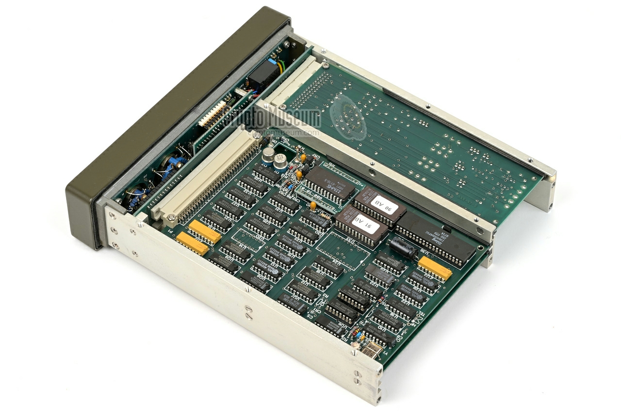
At the bottom side of the device is the
digital board. It is
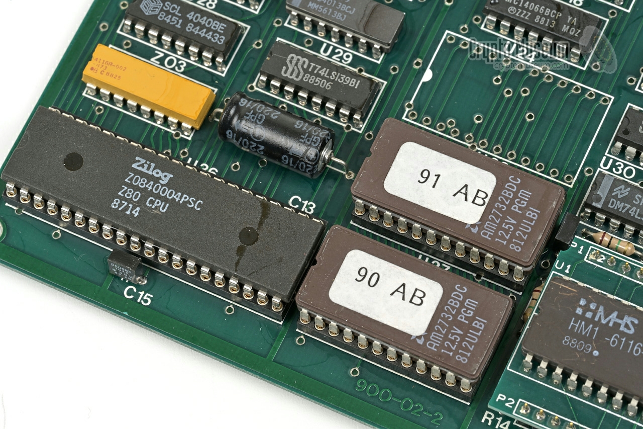
built around a Z80 microprocessor
with two 2732 EPROMs (4KB each) and a
6116 static RAM (2KB).
The contents of the latter are retained by a rechargeable NiCd
backup battery in the corner of the PCB (removed here).
At various places on the PCBs
are configuration straps.
Some of these can be altered manually,
whilst others are permanently soldered in place. In the device
shown here, the permanent straps are configured for HF, which
means that it is suitable for simplex use over HF/VHF/UHF 2-way radio channels.
|
The two devices in our collection were received in December 2025 and were in
mint condition. They don't seem to have any kind of serial number, neither
on the body nor on the inside, which suggests that they were possibly built as
OEM parts. There is no user manual.
To prevent damage from leaking batteries, the
rechargeable NiCd cells had been removed by the former owner.
Since we know the TVC-9000 is a clone of the
Telsy TDS-2004M, we assume that its operation is
largely identical. We also assume that the pinout of the
IN/OUT connector
at the front panel, is identical to the one on the
TDS-2004M.
As we do not have the appropriate cable part for this,
we have not yet been able to test it. We are currently awaiting
delivery of these cable parts.
To be continued ...
|
|
The IN/OUT receptacle at the front panel
is for the connection to a simplex or duplex
radio set. The 12V DC power source for the unit should also be applied here.
It is a standard military 10-way series 12 male receptacle.
The wiring is identical to the TCVR wiring of the
on the Telsey TDS-4000M of which it was a clone.
Below is the pinout when looking into the receptacle.
|
PWR in +12V/DC in SPK out Speaker out REM in Remote key sel. (for 2 keys) TXA out Audio (to radio) GND - Ground MIC in Microphone RXA in Audio from radio REL out Relay (bypass) PTT in Reverse signalling or PTT EAR out Earphone
|
|
|
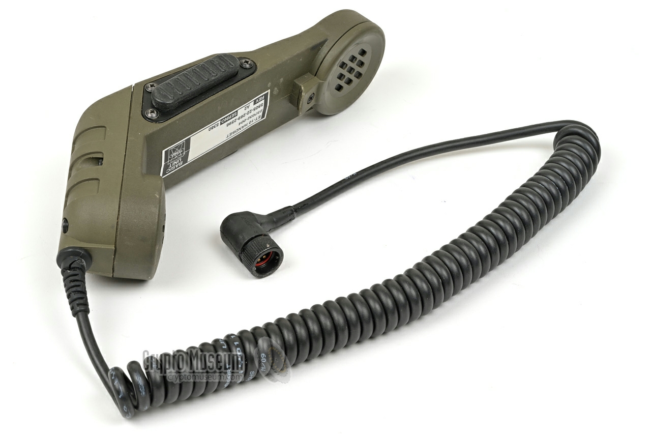
At the far right of the front panel is a 7-pin socket marked HANDSET.
It is an NF7 socket that accepts a standard H-1088/GY military handset
of the German Bundeswehr, such as the ones manufactured by
Telemit.
Note that the wiring for pins (E) and (F) are non-standard.
|
SPK1 Speaker (1) SPK2 Speaker (2) GND Ground PTT Push-to-talk ? unknown 1 ? unknown 1 MIC Microphone
|
|
-
Pins E and F are wired, but we currently don't known what they are used for.
|
Device Frequency and time domain voice scrambler 1 Purpose Secure mobile cellular conversions on analogue network Model TVC-9000 Manufacturer Teltron Year 1984 Country Germany Principle 8 fragment time / 16 fragement frequency division Algorithm Proprietary non-linear Period 500,000 hrs Keys see below Waveform Delta modulation (CVSD) 64 kbps Delay 1 s (in secure mode) Processor Z80 ROM 8KB RAM 2KB Power 11-15V DC (24V optional) Current 300 mA Temperature -10°C to +60°C Storage -20°C to +80°C Humidity ≤ 95% Dimensions 51 × 213 × 252 mm (HWD) Weight 2351 g
|
Compartments 9 (1-9) Digits 1 to 8 per compartment External 108 via front panel (100 million) Custom 107 in firmware Mode Time domain or frequency-and-time domain 1 Storage Battery backed CMOS RAM Battery Rechargeable NiCd
|
- Built-in test equipment (BITE)
- Pseudo digital security
- Long cryptographic period
- Supervisor for suppression of unsuitable fragment combinations
- Microprocessor master control with 8KB program
- Works over standard narrowband voice grade channels
- One- or two-dimensional scrambling
- Wrong polarity and overvoltage protection
- Battery backed key memory
- Dust and splash proof enclosure
|
- Operating instructions
- Technical documentation
|
-
The first digit of the key determines the mode of operation:
(1-5) = time domain scrambling, (6-9) =
frequency and time domain scrambling.
|
-
As the manual for the TVC-9000 is currently not available,
we have listed the manual of the comptible
TDS-2004M from Telsy,
of which the TVC-9000 was a clone. We believe the operation of
the two devices to be largely identical.
|
- Anonymous, Teltron TVC-9000 voice scrambler - THANKS !
December 2025.
- Oscar Steila, Personal correspondence
Former director of Telsy, August 2015.
- Hearings ... Electronic Communications Privacy Act, H.R. 3378, Serial No. 50.
US Government, 26 September 1985 — 5 March 1986.
- Helmut 'Jim' Meyer, HS0ZHK, My way to Ham - Radio and beyond
Website QRZ.COM. Personal correspondence.
Retrieved July 2015.
- Paul Reuvers and Marc Simons, Operation RUBICON
Crypto Museum, 19 March 2020.
- RJ Raggett, ANTSEC Family of Security Equipment
Jane's Military Communications 1985. pp. 542-544.
ISBN 0 7106-0812-8.
- RJ Raggett, ANTSEC Family of Security Equipment
Jane's Military Communications 1986. pp. 505-507.
ISBN 0 7106-0824-1.
|
|
|
|
Any links shown in red are currently unavailable.
If you like the information on this website, why not make a donation?
© Crypto Museum. Created: Sunday 04 January 2026. Last changed: Tuesday, 06 January 2026 - 19:19 CET.
|
 |

|
|
|


