|
|
|
|
|

|
Military reel-to-reel recorder
M-36 was a military portable reel-to-reel 2-track
audio tape recorder
(German: Tonschreiber),
developed in 1971 by AEG Telefunken
for the German Bundeswehr (Army).
The recorder was typically used for presentations (often in combination with
a slide projector) and for recording radio
conversations, for example as part of an
intercept suite.
It was suitable for use in fixed stations as well as in mobile envoronments,
in which case it was supported by a vehicle mount.
|
The device is housed in a die-cast lightweight enclosure with a hinged top
lid. All controls are at the front, whilst the connections are all at the
rear.
It measures just 33.5 × 25.5 × 11 cm and weighs approx. 7 kg.
Standard tape reels are used, which and can played at 4.75, 9.5 or 19 cm/s.
When small diameter reels are used, it is possible to run them
with the top cover closed.
The image on the right shows a typical AEG Telefunken M36 with a tape in place
and the top cover removed. The latter is only possible after removing the two
C-clips from the hinges.
|
|
|
The M-36 is suitable for recording and play-back, for which all connections
are available at the rear. As it is a professional device, balanced inputs
and outputs are available, as well as single-ended outputs on banana-type
sockets. Audio is delivered on a small speaker that is integrated with the
front panel, or to a pair of headphones, selectable with a toggle switch
at the front.
|
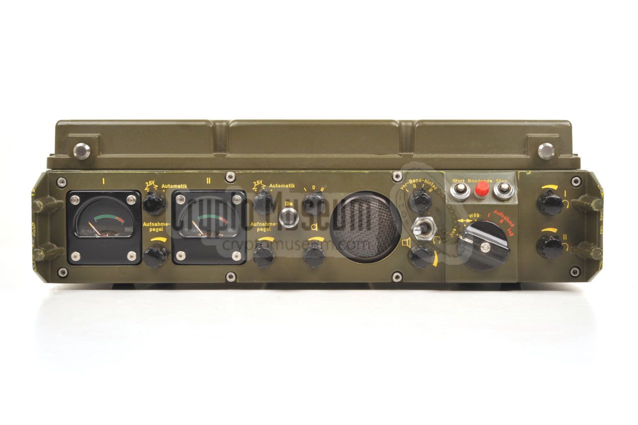
The diagram below shows the front panel of the M36. At the left are the
settings and indicators for the recording level of both input channels
(I and II). At the centre is a round speaker with volume controls.
At the right (somewhat bulged out) is a rotary knob for selecting the
required MODE of operation (record, play-back, winding). Pull-out the knob
to select the (red) recording modes. The tape is started and stopped with
the two push-buttons above the MODE-selector. A small red indicator,
in between these buttons, will be lit when the end of the tape is reached.
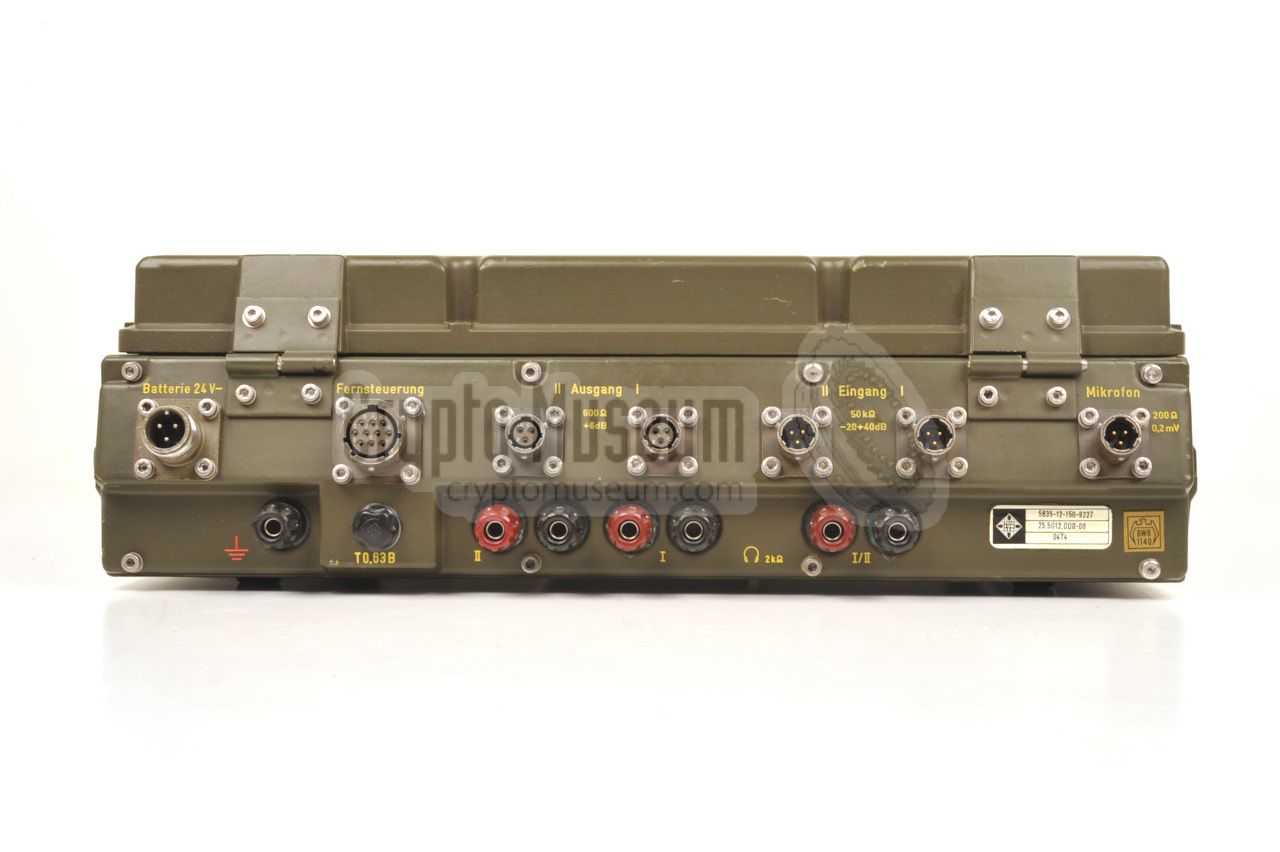
All connections are at the rear. As the device was intended for military
applications, standard military-grade sockets are used. All inputs and outputs
at the top row are balanced. Unbalanced outputs are available on banana sockets.
Headphones should be connected to the banana sockets at the lower right.
A 24V DV power source should be connected to the 3-pin socket at the far left.
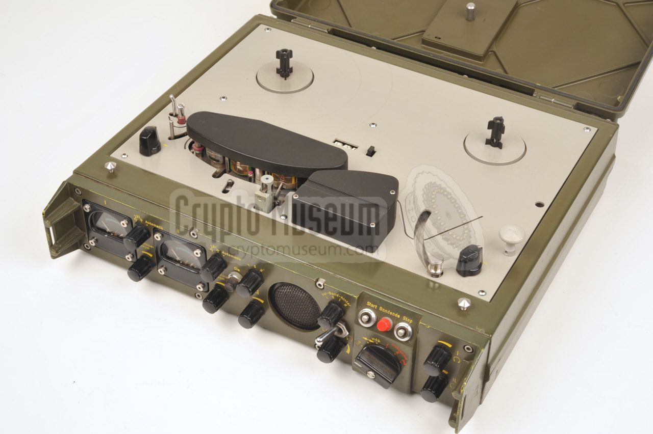
The image above shows a top view of the M-36 on which a small supply tape-reel
is currently installed. In this case, the pick-up reel is somewhat larger.
The tape is guided from the supply reel, past the leftmost tension arm, the magnetic heads, the capstan and the rightmost tension arm, onto the pick-up
reel. Three standard tape speeds are supported, and can be selected
with the 3-position rotary switch at the right. When the MODE-selector (at
the front panel) is set to winding (↔), the winding speed can be adjusted
proportionally with the knob at the front left.
|
|
Getting access to the interior of the M-36 is very simple. If the mechanics
section has to be serviced, the top panel should be removed by taking out 7
hex screws and lifting the panel upwards. This gives access to a die-cast
magnesium frame that holds the motors, pulleys, etc.
|
|
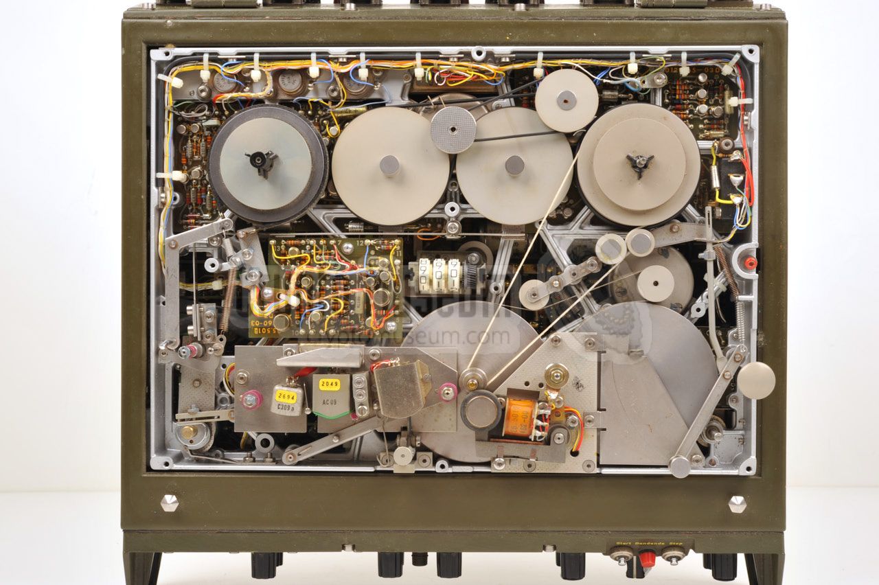
When the underside of the mechanics frame has to be serviced, or when the
electronic circuits have to be accessed, it is not necessary to remove the
top panel. Just loosen the red hex bolt at centre of the right edge of the
top panel and use the knob to pull the hinged frame upwards. It can be locked
in vertical position.
|
|
|
- Ground (chassis)
- + input
- - input
|
- Ground (chassis)
- + output
- - output
|
|
The M36 can be remote controled (start/stop only) from a handheld remote
control unit, or by another M36 unit. The latter is useful when using the
master/slave function to start a second recorder when the first one reaches
the end of the tape.
The diagram below shows the pinout of the 10-pin female socket marked
Fernsteuerung (remote control) at the rear of the machine.
|
- Stop (in) 1
- Remote start (in) 2
- Start (in) 1
- Lamp 3
- Lamp 3
- not connected
- Tape-end (out) 2
- +18V DC (out)
- Electrical ground
- Chassis
|
|
-
Activated by applying +18V from pin H.
-
Pins B and G should be cross-connected between two machines (for
master/slave operation).
-
Lamp 28V/40mA for tape-end warning (output) between pins D and E.
|
Power 24V DC (internally stabilized at 18V) Speed 4.75 - 9.5 - 19 cm/s Size 337 × 324 × 110 mm Weight 7 kg
|
|
|
|
Any links shown in red are currently unavailable.
If you like the information on this website, why not make a donation?
© Crypto Museum. Created: Saturday 16 July 2016. Last changed: Wednesday, 05 November 2025 - 11:46 CET.
|
 |

|
|
|