|
|
|
|
|

|
Covert two-way VHF radio · USSR
Kaira (Russian: Кайра) 1 is a body-wearable
covert radio,
developed in the USSR
in the 1980s. It was used by the MKV 2 and by the
KGB
for covert operations, surveillance and observations.
It has a wire antenna that can
be hidden under the operative's clothing, and operates
in the 150 MHz band (2 meter).
An optional voice scrambler adds
a limited level of speech security to the radio.
|
The radio is housed in a curved enclosure that was shaped in such a way that
it could easily be carried on the body of an operative, concealed under the
clothing. All connections are at the top of the device and all controls are
on a handheld remote control unit
that is at the end of a cable that runs through the sleeve of the
user's coat.
The handheld remote control unit also acts as the microphone/speaker, but
some units came with a small external speaker
that can be hidden under the collar of the coat.
It was attached to the clothing by means of a
safety pin at the rear.
|
|
|
Although it was possible to connect a
vertical antenna,
most Kaira units came with a special
wire antenna that had
several safety pins along its
length, allowing it to be concealed under the operative's clothing.
The radio is powered by a 7.2V battery back,
that is installed from the top.
When used by the KGB and other secret services, Kaira was often issued
with an (optional) speech scrambler, that protected the
communication against the occasional eavesdropper. Contrary to popular
believe though, this scrambler is not built-in, but is an
optional external add-on
[5].
|
-
Кайра (Kaira) is Russian for Guillemo.
Kaira is sometimes written as Kajra or Kayra.
-
MKV = Ministry of Internal Affairs of the Soviet Union (USSR).
This includes the military police, regular public safety police, traffic
police (GAI), customs and interior troups (VV). Often confused with the
KGB.
|
The diagram below gives an overview of the components that were part
of the Kaira radio station. At the centre is the actual radio body,
which has a curved shape so that it can be carried on the body more
easily. It is shown here with a battery installed.
At the left is the wire antenna, that was concealed under the
clothing, using safety pins to attach it to the clothing at various
places.
At the right is the handheld controller, of which
various designs
were available. The one shown here has an
external microphone/speaker,
which is visible at the bottom left, but there was also a model with
a built-in microphone/speaker.
The external speaker has a safety-pin at the rear,
so that it can be attached below the collar of a coat.
The controller was usually carried in the hand,
with the flexible cable running through the sleeve of the coat.
This allows the user to control the push-to-talk (PTT) switch and
adjust the volume, without this being visible to a bystander.
The radio works in the 2-meter radio band, between 152 and 172 MHz,
and was usually populated with crystals for two channels. Switching
between the two channels is done with the
recessed switch at the bottom of the unit.
The channel was never changed during an operation.
|
|
As far as we know there were two Kaira models, but the differences
are currently unknown. The following models are known:
|
- Kaira
This is the basic Kaira model that was introduced in the 1980s.
It was available with three different types of controller, of
which two models are featured in this page. It is believed that the
Kaira shown here, is the basic model.
- Kaira-M1
This was a slightly modified version of the radio, but the exact
differences are currently unknown. It is possible that the only difference
was the simplified antenna socket, as shown in
this image.
|
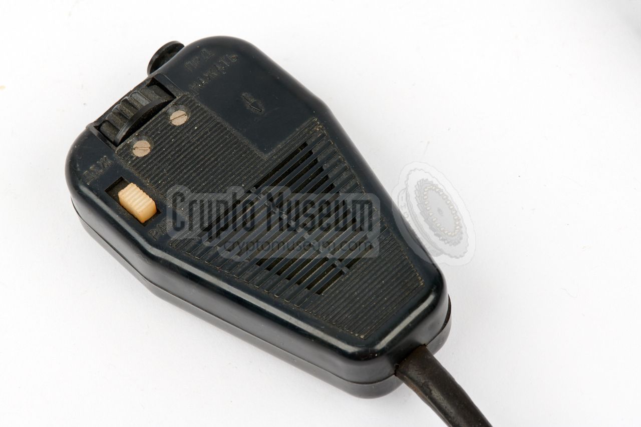
All functions of the radio are controlled with the externally connected
remote control unit, or controller. It is shaped in such a way
that it nicely fits inside the hand. It is connected to the radio by
means of a 1 metre flexible cable, that is usually guided through the
sleeve of the coat.
The controller holds the push-to-talk switch (PTT), the volume adjustment,
and a switch to select silent operation. Some versions of the
controller had a built-in microphone
rather than an external one.
|
|
|
For covert use, the radio was usually supplied with a concealable
microphone/speaker, such as the PDM-1 model shown in the image on the
right. It has a safety pin at the rear,
so that it can be attached
to the clothing, for example under the collar of a coat.
When a controller with built-in speaker
was used, the external speaker was omitted.
|
|
|
The radio is powered by six rechargeable 1.2V AA-size NiCd battery cells,
that are housed in the long rectangular battery packet shown in the image
on the right. It should be installed in the battery slot at the top of
the Kaira radio, and does not go all the way in. About 2 cm of the
battery pack will be sticking out from the top.
Kaira uses the same batteries as Chaika.
It is currently unknown how they were charged, but this was
probably done with an external battery charger. Spare battery
packs must have been available to power the radio in the meantime.
|
|
|
For the best performance, the radio should be used with
a vertical antenna, that can freely radiate in all directions.
When concealing the radio on the body however, this is not possible.
For such situations, the wire antenna shown in the image on the
right is used as a compromise. It decreases the performance of the
radio, but has the advantage to be completely invisible.
The wire has safety pins at various points,
so that it can be easily attached to the clothing.
|
|
|
In non-covert (i.e. overt) situations – such as common police surveillance –
where good performance was important, a straight vertical ¼λ antenna
could be fitted to the radio.
The antenna is shown in the image on the right. It consists of two pieces:
a flexible part in a rubber sleeve, and a shorter thin piece that can be
mounted on top.
The antenna shown here can only be
fitted to the Kaira-M1.
|
|
|
|
|
Speech scrambler
wanted item
|
|
|
To add some level of voice security, an optional speech scrambler could
be installed externally. It was connected between the handset (controller)
and the 16-pin socket on top of the radio. The image on the right shows
an original Kaira Voice Scrambler, as it is held in the collection of the
KGB Spy Museum in Lithuania [5].
It is implemented as a simple
frequency inverter,
that was only intended for protection against an occasional or
accidental eavesdropper. It offers no protection against a professional
interceptor, as speech scramblers in general are insecure.
➤ More about speech scramblers
|
|
|
For covert operations, a special cloth body harness was usually supplied
with the radio. It allowed the radio to be carried inconspicuously under
the operative's clothing. The radio is fitted inside one of the pockets
of the harness, as shown in the image on the right [5].
The image also shows the optional external speech scrambler, which is
described above. Both the harness and the scrambler are currently missing
from our collection. If you have spare items, please contact us.
|
|
|
|
Kaira is housed in a plastic enclosure that consists of two plastic case
shells, held together by a molded metal cover at the top and at the bottom.
Opening the radio is really simple and involves the removal of just
three screws. First remove the two recessed screws from the rear panel.
|
Next, remove the
single screw at the centre of the bottom cover.
Note that
this screw may be sealed and be prepared to remove the wax if necessary.
After the bottom cover is removed, the plastic front and rear case shells
can also be removed. The interior will now be exposed.
The radio consists of
two printed circuit boards (PCBs):
a bigger one
that holds the receiver, and a smaller one – with the transmitter – at the side.
The image on the right shows Kaira's interior, with the receiver at
the front and the top panel at the left. At the right is the
channel selector.
|
|
|
|
The empty space at the front is normally taken by the battery pack, for
which two spring-loaded contacts are present.
The radio consists of a large number of modules that are housed
in a metal enclosure that is very similar to a crystal. The function of
each module can be determined from the number at the top, e.g. M06-20.
The radio shown here was manufactured in January 1990.
|
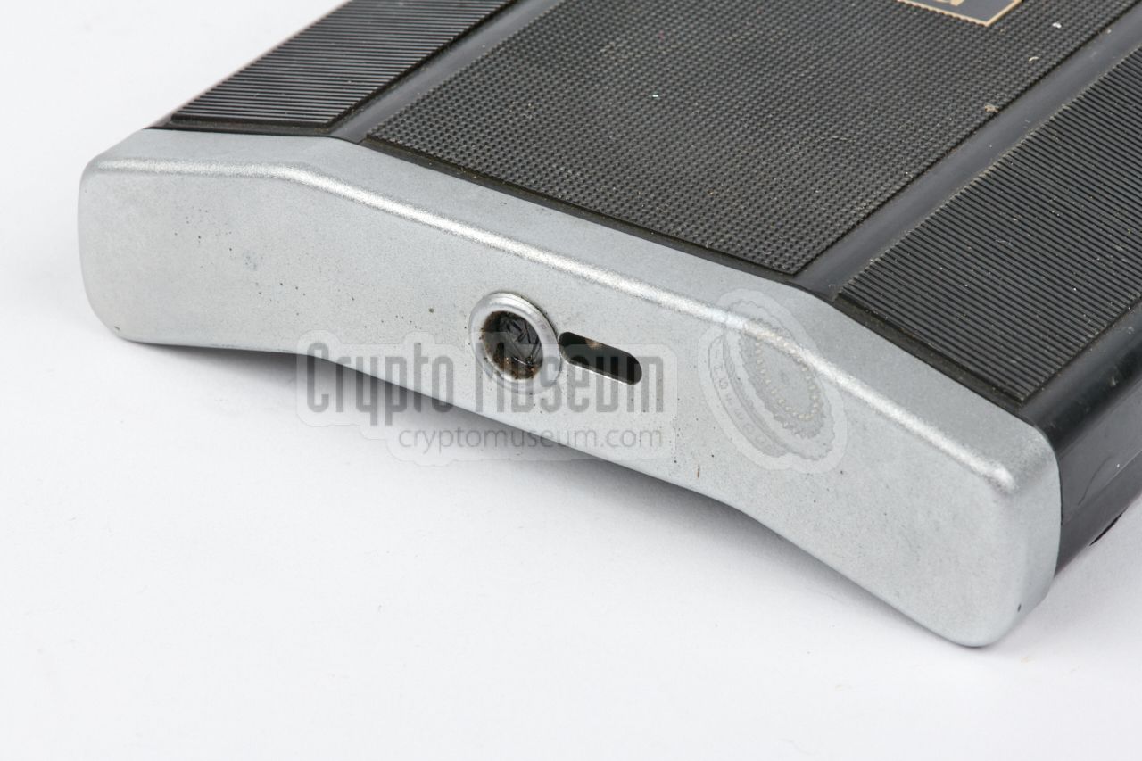
Apart from the antenna socket, there is only one socket at the top panel.
It is a typical 16-pin USSR bus
to which the controller
should be connected. All control and audio signals are available on this
socket. The wiring of the socket can be determined from the
circuit diagram.
Note that the optional voice scrambler
should be connected between the controller and this socket.
|
Voltage 7.2V DC Current 20 mA (RX), 350 mA (TX) Power output 0.3 - 0.5 Watts Frequency 148 - 173 MHz ➤ see table Channels 2 Dimensions 177 x 115 x 23 mm Weight 336 grams (without battery and control unit)
|
|
Depending on the customer and the application, the radio was manufactured
and aligned for a specific frequency band, as assigned by the USSR Ministry of
Internal Affairs (MVD). Three MVD bands are known — A, Б and X — covering the
following frequencies (40 channels each) [4]:
|
A 148.000 - 148.975 MHz B 172.000 - 172.975 MHz X 171.100 - 172.100 MHz (mixed) 1
|
|
The Kaira radios in our collection all have the same two channels in the A-band:
11 (148.125) and 31 (148.175). Althoug in the frequency table, channel two is
20 steps away from channel 1, the actual frequencies are just 50 kHz apart.
This is because the frequencies are not contiguous.
|
-
Band B and band X share three channels:
00 (172.000), 01 (172.100) and 20 (172.050).
|
We are still looking for additional information about this radio, such as
manuals, circuit diagrams, technical details, and backgrounds on where and
how this radio was used. We are also looking for the optional
speech scrambler – that was connected externally –
and the body harness,
that allowed the radio to be carried on the body.
If you can help us in any way, please contact us.
|
- Радиостанция Кайра - Kaira user manual (Russian)
ЯЕ 2.000.151 TO. Date unknown. Available via [1].
- Kaira circuit diagram
Retrieved December 2017 [3].
|
-
Images reproduced here by kind permission from the author.
|
|
|
|
Any links shown in red are currently unavailable.
If you like the information on this website, why not make a donation?
© Crypto Museum. Created: Monday 05 May 2014. Last changed: Friday, 16 November 2018 - 13:12 CET.
|
 |

|
|
|


![Optional speech scrambler. Photograph kindly supplied by KGB Spy Museum [5].](img/kaira_scr2_large.jpg)
![Cloth harness with Kaira radio and optional speech scrambler. Photograph kindly supplied by KGB Spy Museum [5].](img/kaira_scr1_large.jpg)


