|
|
|
|
|

|
|
NRP CIA EC SRS-153 UVK-153 → ← SRR-153
The QRT-153 operates in the 70 MHz band and was generally
placed in the vicinity of the target area. In most cases it was installed
as part of the listening post (LP), which was generally located across
the street from the bugged target area.
The image on the right shows a typical QRT-153 unit that has provisions for
controlling up to four bugs simultaneously. It allows precise control of
the transmission frequency, as well as control of the carrier tones that are
used for the ON and OFF commands, via a field of 24 thumb-wheels, located
behind a plexiglass panel at the top left.
|
|
|
The device has a built-in telescopic antenna
that should normally be
sufficient to reach the QRR-153 switch-receiver
directly. If necessary,
an external antenna can be connected instead. When sending an ON or OFF
command tone, one has to bear in mind that the QRR-153 switch-receiver
is only activated for 23 ms every 1.5 seconds, so the tones
should be sent at least that long.
The activation tones are well above the audible range, so that they would
not raise any suspicion when the signal was accidently intercepted by someone
tuning into a station in the FM broadcast band. The frequencies on which the
(de)activation signals are sent are at the lower end of the broadcast band
and was used in the past in many countries by public services like the police,
and nation-wide paging systems. Sending a brief signal in this band would
not raise any suspicion.
|
All controls and connections of the QRT-153 are located at its front panel.
The device has the same footprint (26 x 17 cm) as the SRR-153 surveillance
receiver, so that it can be placed on top
if the available space is limited.
Power is provided by internal or external batteries, or by the AC mains.
Connections for external power sources are provided at the right edge
of the front panel.
When an external antenna is required, the
BNC bridge plug
at the top right should be removed.
The large meter
provides an indication of the transmitter's RF output power, as measured by
an internal directional detector.
It can also be used for measuring the reflected energy or the
battery voltage, by pressing one of the buttons immediately below it.
The output power is automatically reduced when too much energy is reflected,
so that the PA can not be damaged by a bad VSWR.
At the top left are the thumbwheels for setting the ON/OFF tones
and the RF frequency.
Each function has four presets, selectable by the
channel selector at the bottom.
To prevent accidental change of the settings, the tumbwheels are protected
by a plexiglass panel that is held in place
by four screws at the corners.
This panel should be removed before changing the settings.
At the bottom left is the command knob. It is a momentary switch, that should
be pushed right to send the ON command, and left to send the OFF command,
for the selected channel 1 - 4. The correct timing is selected automatically
by the internal control unit. If necessary, a simple remote control unit
can be be connected to the 3-pin LEMO socket
at the right, allowing an
observation team to quickly turn the bug OFF
in case of an emergency (e.g. when a sweep team is spotted).
|
The diagram below shows a complete setup of the
SRS-153 surveillance system.
The SRT-153 transmitter
is installed at the target area (TA) at
the bottom right. It is powered by two strings of
five Mallory mercury cells each, under control of the
QRR-153 switch-receiver at the top right.
At the listening post (LP), which is generally located across the
street from the target area, is the
QRT-153 activation transmitter,
which can send two carriers (one for the ON command and one for OFF)
via a frequency in the 70 MHz band. It has presets for controlling
up to four QRR/SRT-153 sets simultaneously. Once activated, the
signal from the SRT-153 transmitter can be picked up by the
SRR-153 surveillance receiver
at the bottom left. The latter can also be replaced by an
SRR-90 receiver which has been modified for
the reception of subcarrier-modulated transmitters.
|
Below is the block diagram of the QRT-153 actuator.
Central to the system are two frequency synthesizers:
one for determining the RF transmission frequency in
the range 68 to 78 MHz (C),
and one for creating the ON and OFF command tones in
the range 14 to 24 kHz (B), both driven
by a central timing unit (A).
The 3 boards (A) (B)
and (C) are interconnected via
a backplane (D).
The desired frequencies are defined by setting
a divider (n) by means of the thumbwheels at the left, in the range 00-99.
Separate thumbwheels are available for each of the four preset channels.
The upper synthesizer (C)
drives a VCO (E) which in turn drives
a power amplifier (F) from which the output is passed via a directional
detector to the antenna. The directional detector accurately measures the
outgoing and the reflected power and sends a control signal back to the
modulator (G). The latter controls the PA and is driven by the central
control and timing unit on board (A).
|
The QRT-153 was developed especially for use with the
QRR-153 miniature switch-receiver.
The latter is factory-tuned to a specific frequency in the 70 MHz band,
and responds to two factory-defined command tones, that are used to
control the SRT-153 miniature transmitter (bug).
Each QRR-153 was supplied with a test sheet on which the
factory-defined frequencies were specified. These values were used to
set the position of the thumbwheels at the front panel.
➤ More information
|
|
|
|
The QRT-153 is housed in a strong grey metal enclosure that measures
26 x 17 x 18.5 cm. It consists of a strong metal frame that holds all
parts, including the front panel, surrounded by a metal case shell that
is held in place by six screws around the edges of the recessed front panel.
|
After removing the six screws from the case shell, and removing the
battery pack at the rear, the case shell can be taken off, revealing the
internal frame. The various
building blocks are
each identified by a letter of the Latin alphabet.
The three major circuits, comprising the control & timing unit
and two synthesizers, are each on a separate PCB (marked A,
B
and C) and are installed
at the left,
in a vertical backplane (D).
The image on the right shows the upper board of the stack (A).
Along the far edge is the 1.024 MHz crystal from which all
timings are derived.
|
|
|
The voltage controlled oscillator (VCO) that provides the RF signal,
the 20 dB power amplifier (PA) and the directional detector, are mounted
in two separate metal enclosures,
marked (E)
and (F),
at the rear right of the internal frame.
The modulator/ALC (G)
is mounted to the front
of the unit (E).
|
It controls the power supply to the PA (F)
under control of the subcarrier
tone from the command synthesizer (B),
causing Amplitude Modulation (AM) of the RF signal.
This unit also provides the Automatic Level Control (ALC),
directed by the forward signal from the
directional detector (F).
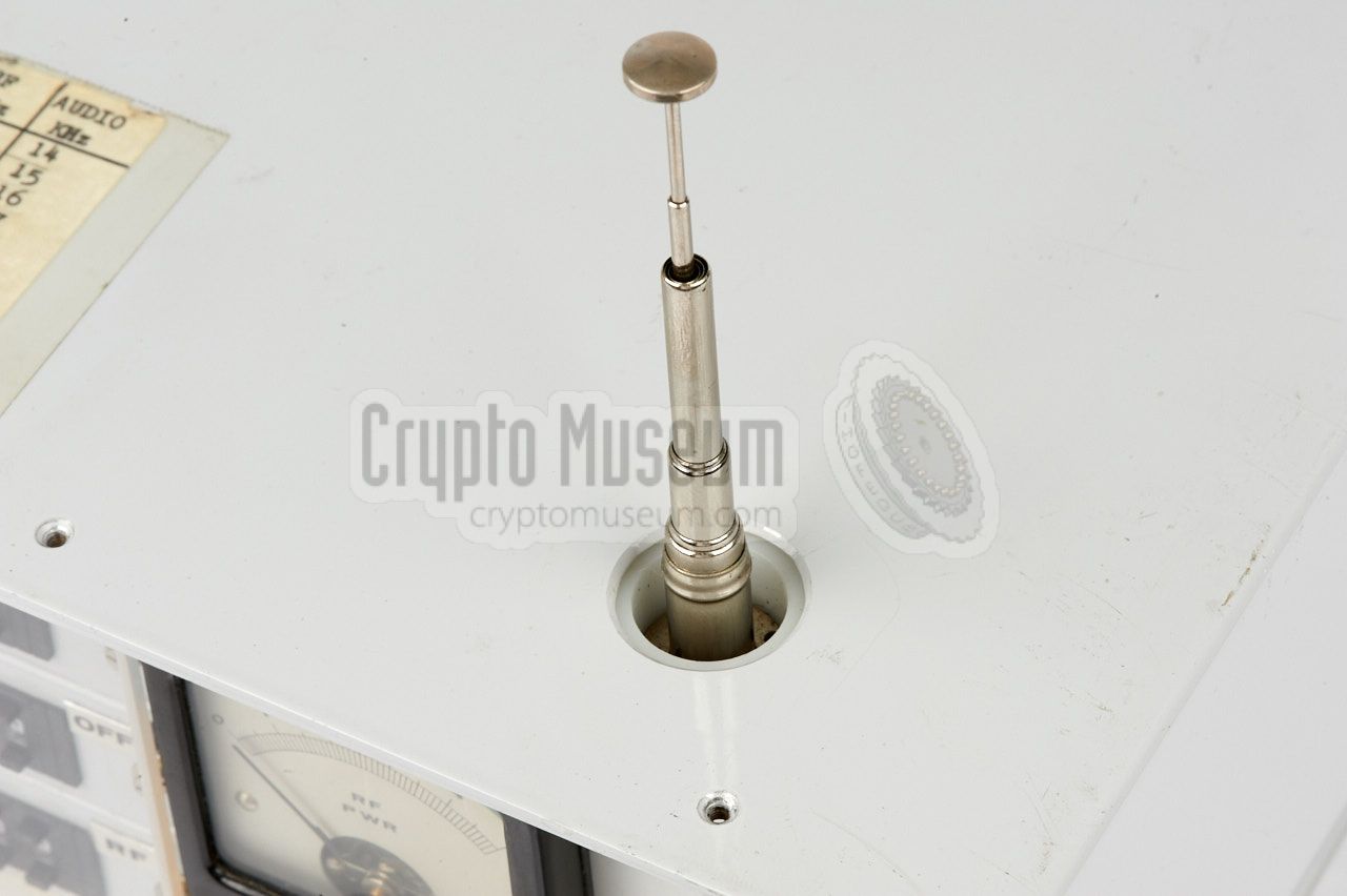
The QRT-153 has an internal telescopic antenna that is isolated by
a teflon mounting, fitted to the rear of the front panel. It is
matched by a series connected coil. It is looped via the front panel,
by means of a bridge plug,
so that it can be replaced by an external antenna if necessary.
|
|
|
When extended, the internal antenna
protrudes a hole in the top
surface of the outer case shell. To the left of the antenna is a
large meter that shows the (forward) antenna power. It can also
show the amount of reflected power or the battery voltage, by
pressing the corresponding push-button on the front panel.
A simple mains PSU is mounted at the
bottom of the internal frame.
|
- Control and timing unit (1.024 MHz reference oscillator)
- Subcarrier frequency synthesizer (14 - 24 kHz)
- RF frequency synthesizer (68 - 77.9 MHz)
- Backplane (interconnection board)
- RF VCO (68-77.9 MHz) and ÷100 prescaler
- Power Amplifier (PA) and directional detector
- Modulator / Automatic Level Control (ALC)
|
00 68 MHz 10 69 MHz 20 70 MHz 30 71 MHz 40 72 MHz 50 73 MHz 60 74 MHz 70 75 MHz 80 76 MHz 90 77 MHz 99 77.9 MHz
|
00 14 kHz 10 15 kHz 20 16 kHz 30 17 kHz 40 18 kHz 50 19 kHz 60 20 kHz 70 21 kHz 80 22 kHz 90 23 kHz 99 23.9 kHz
|
|
The QRT-153 can be powered in three ways, controlled by a 4-position
rotary switch at the front panel. In the leftmost position, the device
is fully turned off. Note that all circuits are designed in such a way,
that they do not draw any current when the device is not actively
sending a signal.
|
- AC Mains 100-135V or 200-270V AC (50/60 Hz)
- Internal batteries (10 x 1.5V C-size)
- External battery 11 - 16.5V DC (connected via front panel)
|
|
A simple remote control can be connected to the
3-pin LEMO socket
at the right of the front panel. The common contact of a single-pole
double normally-open (n.o.) momentary
switch should be connected to the male pin (3) of the socket.
This duplicates the front panel switch.
|
- Proposal for Prototype SRS/QRS-53
NRP, November 1977. CM302627/B.
- Concise Operating Instructions for QRT-53 Actuator
NRP, March 1979. 2 pages. CM302627/C.
- Manual for QRT-53 Actuator
NRP, April 1979. CM302627/D.
- Environmental Test Report on XQRT-53 Actuator
NRP, July 1979. CM302627/E.
- Manual for QRT-153 Actuator
NRP, September 1981. CM302627/P.
|
- NRP/CIA, Collection of documents related to SRS-153
Crypto Museum Archive, CM302627 (see above).
|
|
|
|
Any links shown in red are currently unavailable.
If you like the information on this website, why not make a donation?
© Crypto Museum. Created: Thursday 18 May 2017. Last changed: Monday, 21 November 2022 - 13:30 CET.
|
 |

|
|
|