|
|
|
|
|

|
|
NRP CIA EC SRS-153 QRT-153 → ← QRR-153
The receiver covers a frequency range from 260 to 320 MHz in a single
linear band,
and can demodulate a 22 KHz frequency modulated subcarrier. Some versions
were (optionally) also capable of demodulating a 44 kHz subcarrier. 1
It was developed especially for the reception of the SRT-153,
which was merely a 'chinese copy' of a bug developed by an unknown adversary,
that was found in the desk of a US Ambassador in the mid-1970s. The CIA
went through great lengths to copy every aspect of the bug, from the
choice of components to the enclosures. 2
|
|
|
Unlike earlier
CIA surveillance receivers,
like the versatile and modular
SRR-90
and SRR-91,
the SRR-153 can only be used for the reception of
transmitters (bugs) that feature subcarrier audio masking, such as the
SRT-93 and the
SRT-105, both developed by different
CIA contractors. The SRR-153 was used at the heart of a listening post,
commonly alongside the QRT-153 actuator.
Although the SRT-153 transmitter
and the QRR-153 switch-receiver
are near exact copies of the original ones,
the peripheral equipment was developed by
the NRP from scratch.
The SRR-153 is part of the SRS-153 surveillance system
and was added to the range in 1981, with full production starting
in 1982, three years after the launch of the system.
In was in production until at least 1985.
Until its launch, an upgraded version of the
SRR-90 had been used
as an interim solution.
|
-
This was done by setting a jumper on the audio board.
-
For more information, check out the
history of the SRS-153.
|
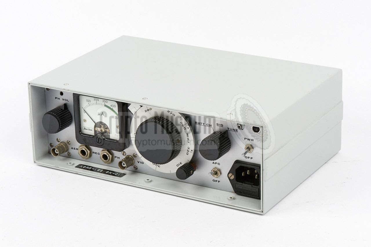
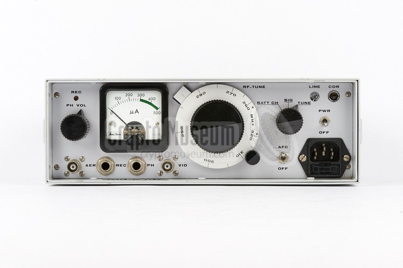
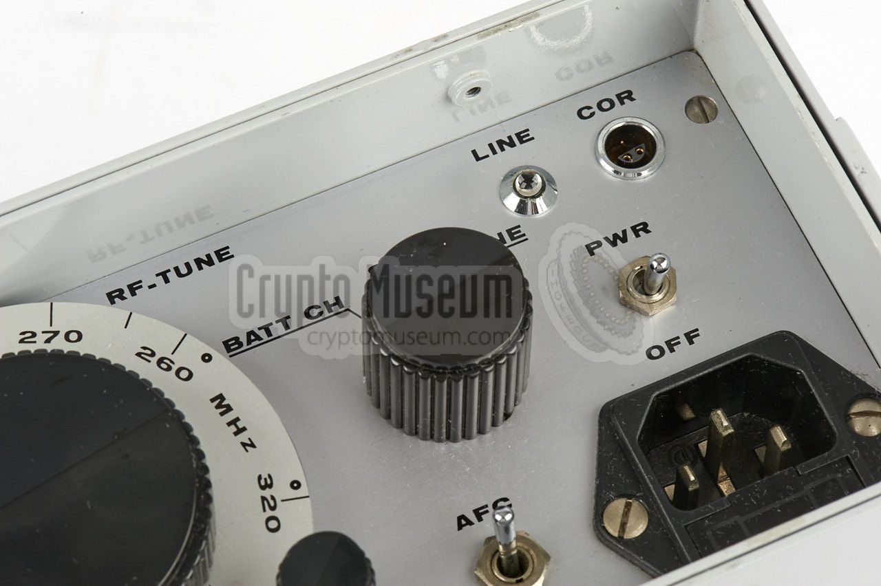
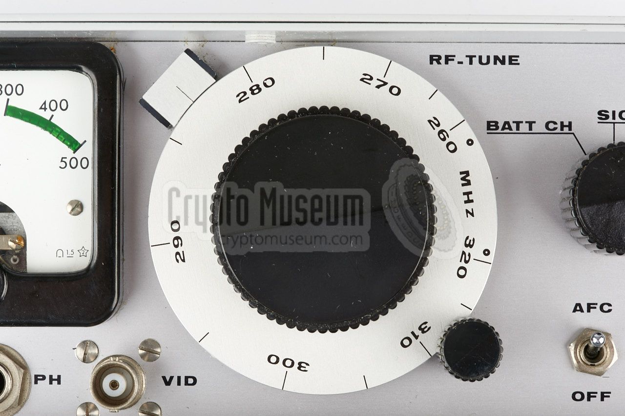
All controls and connections are located at the recessed front panel of
the SRR-153. At the bottom right is an euro-socket for connection
of the mains power cable. The ON/OFF switch is located immediately
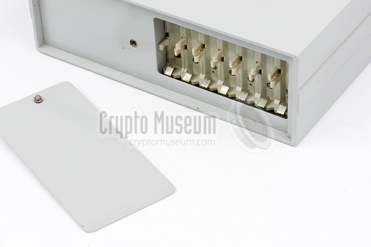
above it. Alternatively, the unit can be powered by internal batteries
that should be installed in the special compartment
at the rear. Seven 1.5V AA-size batteries are used.
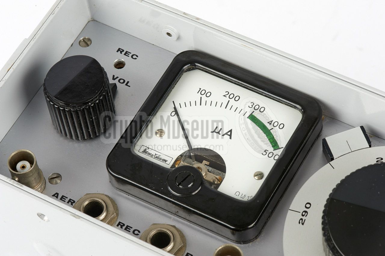
Central to the front panel are a large tuning knob (with a fine-tuning
knob at the bottom right) and a clear indicator (meter) to measure the
signal strength, discriminator and battery voltage. At the far left is
the volume knob. Apart from this, the SRR-153 has no further controls.
Unlike the earlier SRR-90 receiver, it is only suitable for the reception
of subcarrier-modulated bugs.
Connections for antenna and headphones are at the bottom left.
A separate output is available for a recording device, which can be
started and stopped automatically, by using a relay contact that is
available on the COR socket at the top right. The wideband IF-signal
is available from the VID socket (video) at the bottom edge.
It allows the signal to be processed by external hardware.
|
|
The following CIA bugs are known to work with the SRR-153:
|
The diagram below shows a complete setup of the
SRS-153 surveillance system.
The SRT-153 transmitter is installed at the target
area (TA) at the bottom right.
It is powered by two strings of
five Mallory mercury cells each, under control of the
QRR-153 switch-receiver at the top right.
At the listening post (LP), which is generally located across the
street from the target area, is the
QRT-153 activation transmitter,
which can send two carriers (one for the ON command and one for OFF)
via a frequency in the 70 MHz band. It has presets for controlling
up to four QRR/SRT-153 sets simultaneously. Once activated, the
signal from the SRT-153 transmitter can be picked up by the
SRR-153 surveillance receiver
at the bottom left. The latter can also be replaced by an
SRR-90 receiver which has been modified for
the reception of subcarrier-modulated transmitters.
|
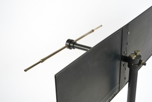
A suitable directional antenna for the SRR-153 listening post (LP)
is the SRN-9-L, or the later SRN-9. It offers a gain of 7 dB and is
in fact an adjustable dipole on a horizontal boom (which acts as a
balun), mounted in front of a reflector.
The antenna can be disassembled completely, and the reflector plane
can be folded at the centre, so that the entire unit can be stored inside
a regular briefcase, along with the SRR-153 receiver and its accessories.
➤ More information
|
|
|
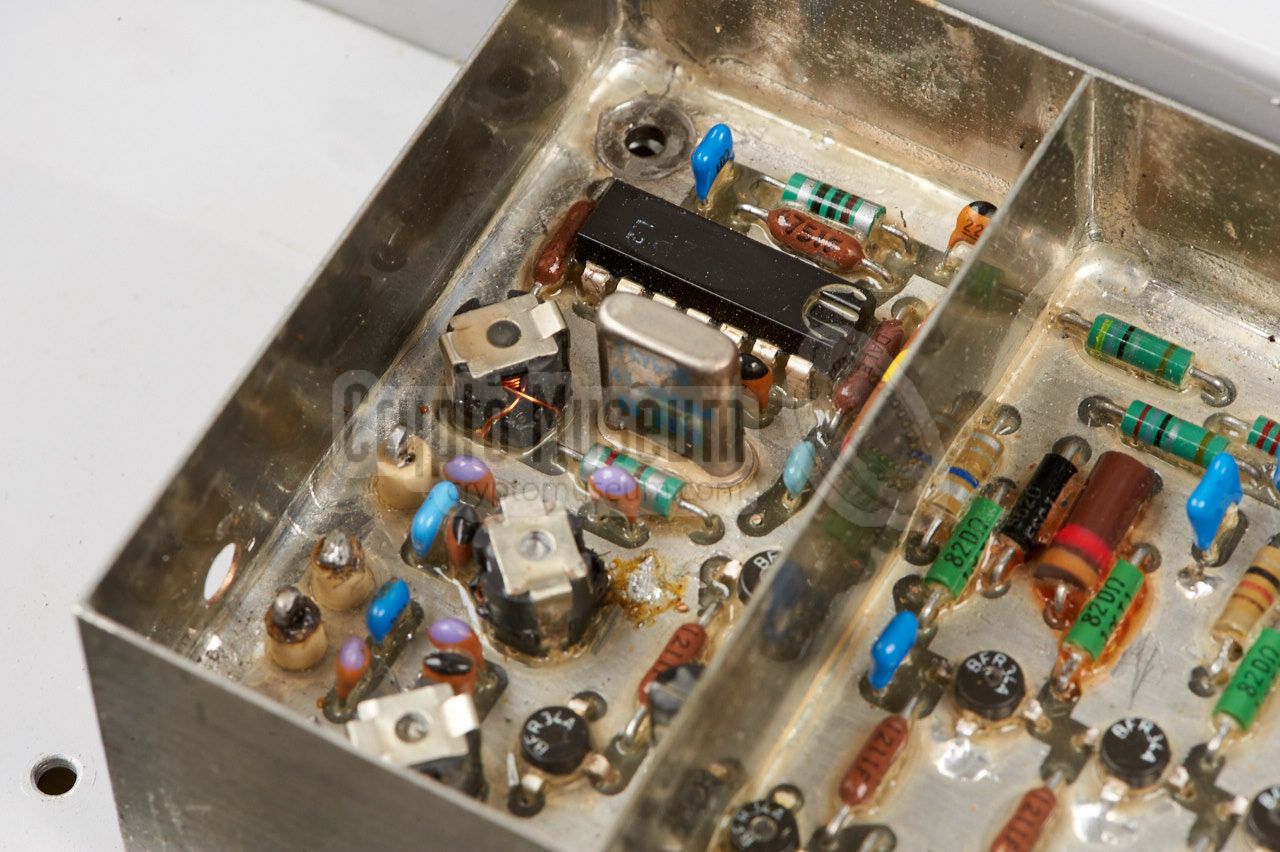
Below is the block diagram of the SRR-153. At the left is the tuner that is
housed in a separate fully shielded enclosure. Its output fed to the IF section
at the top right. Once the FM signal is discriminated, the resulting video
signal is fed through a 22 kHz (or 40 kHz) bandpass filter, onto the
subcarrier demodulator. The resulting signal is filtered, amplified
and supplied to the phones.
The signal from the demodulator is also fed through a 10 kHz bandpass filter,
onto a noise detector that drives the squelch circuit as well as the (delayed)
COR output. The latter is used to start/stop an external recording
device. The video signal is also used for the AFC. Note that some versions
have a jumper on the audio board, to select between a 22 kHz and a 40 kHz
subcarrier.
|
|
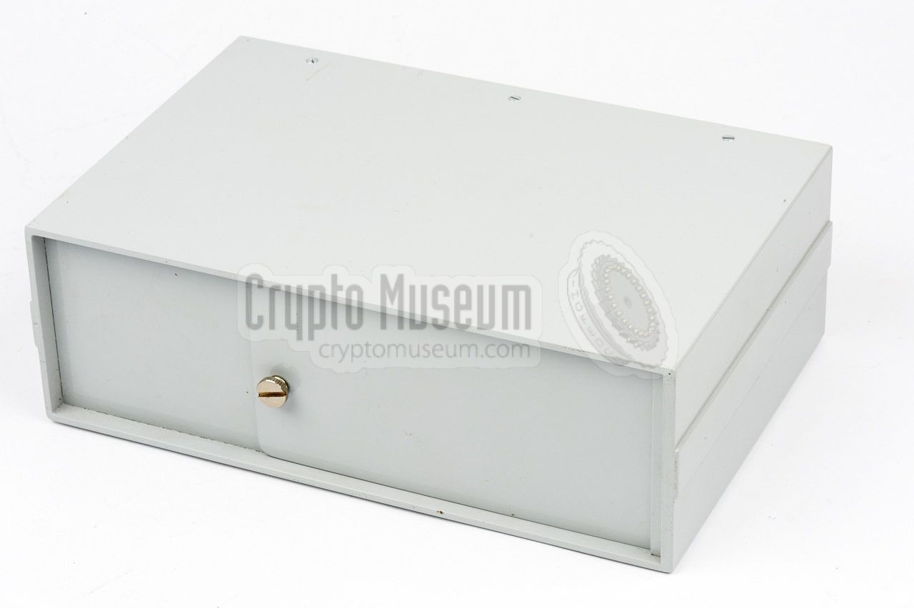
The SRR-153 is housed in a sturdy metal enclosure that measures
26 x 17 x 8.5 cm. It consists of a metal frame that holds all of the
internal parts plus the front panel, enclosed by a metal case shell
that is held by six screws around the edges of the front panel,
plus a large one at the rear.
|
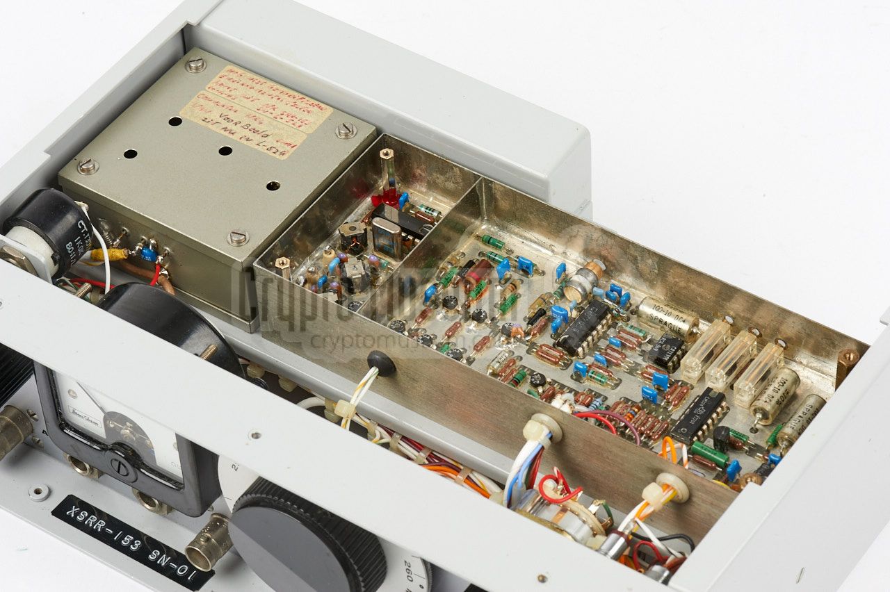
After removing the six screws plus the lid of the battery compartment
at the rear, the case shell can be removed and the internal frame will be
exposed. The image on the right shows the top half of the frame, which
holds the RF tuner, the IF strip and the tuning control plus AFC section.
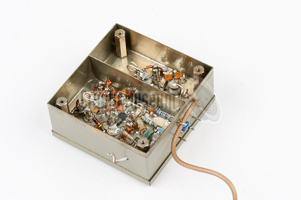
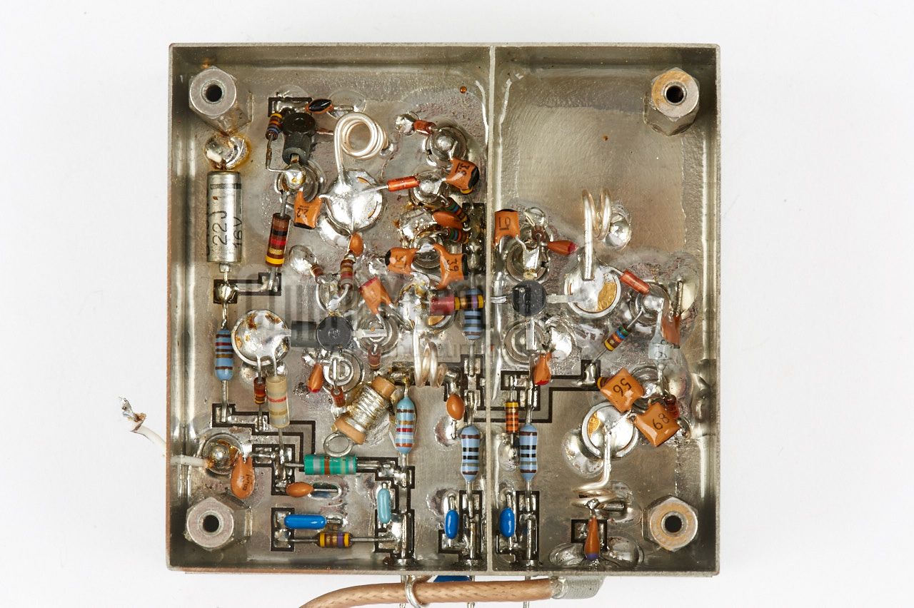
The RF tuner is the closed square box at the left.
All tuning is by means of VARICAP diodes, under control of a linear
adjustable voltage that can be adjusted with
three internal multi-turn potentiometers,
in order to calibrate the tuning scale
at the front panel for the full 260 - 320 MHz range.
|
|
|
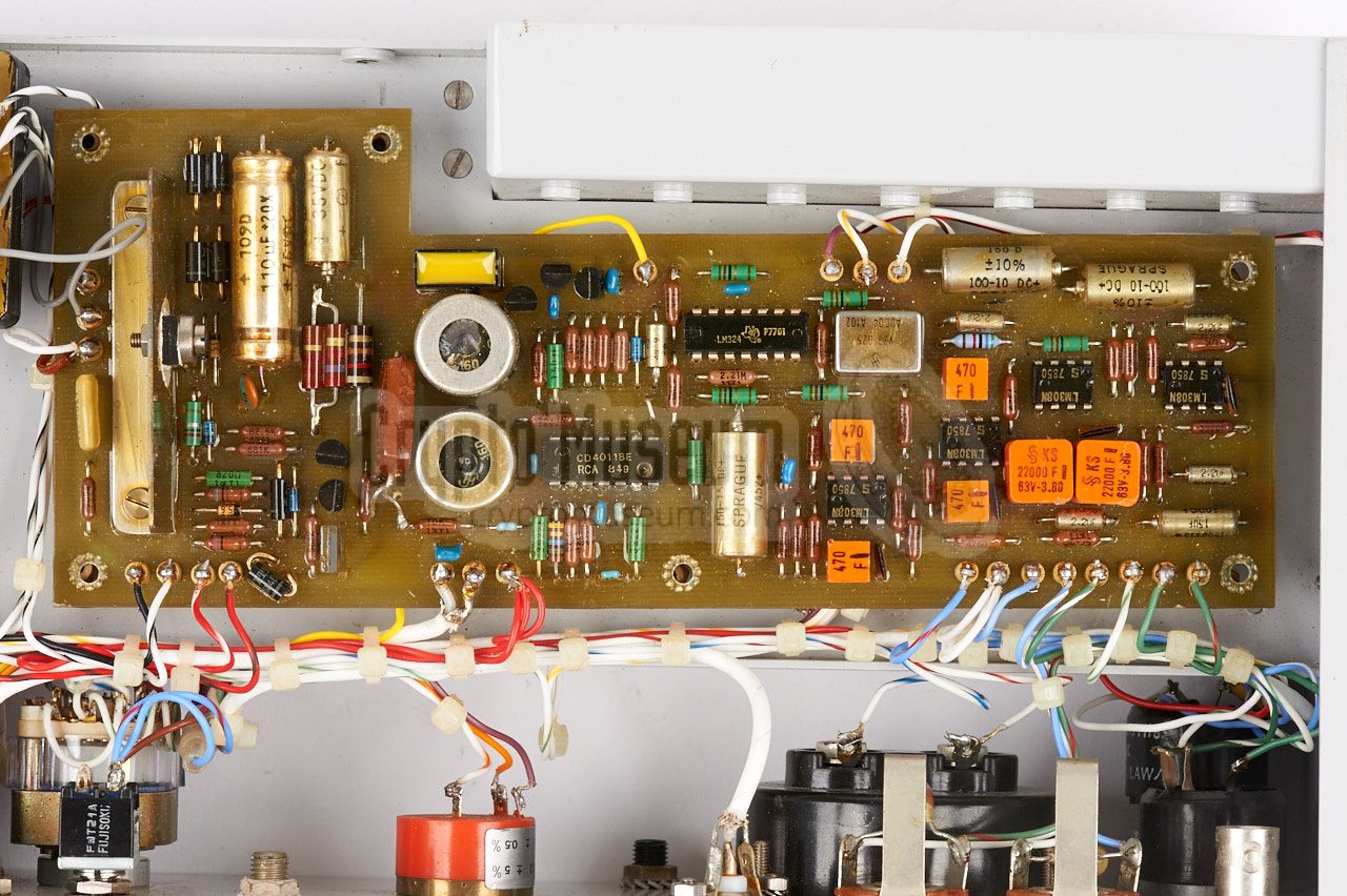
The bottom side of the frame holds the mains transformer and PSU,
the audio amplifier and the COR. The latter automatically detects a valid
subcarrier-modulated signal and turns off the noise canceller.
It also controls a relay that can be used to start/stop an external
recording device.
|
- Proposal for Prototype SRS/QRS-53
NRP, November 1977. CM302627/B.
- Preliminary Partial Manual for XSRR-153 Receiver
NRP, 7 May 1981. CM302627/L.
- Environmental Test Report on XSRR-153 Basic Receiver
NRP, July 1981. CM302627/M.
- Operating and Test Manual for XSRR-153 Receiver
NRP, September 1981. CM302627/O.
- Operating and Test manual for SRR-153 Receiver
NRP, November 1983. CM302627/Q.
- Environmental Test Report on SRR-153 Receiver
NRP, November 1983. CM302627/R.
|
- NRP/CIA, Collection of documents related to SRS-153
Crypto Museum Archive, CM302627 (see above).
|
|
|
|
Any links shown in red are currently unavailable.
If you like the information on this website, why not make a donation?
© Crypto Museum. Created: Thursday 18 May 2017. Last changed: Monday, 21 November 2022 - 13:29 CET.
|
 |

|
|
|