|
|
|
|
|

|
|
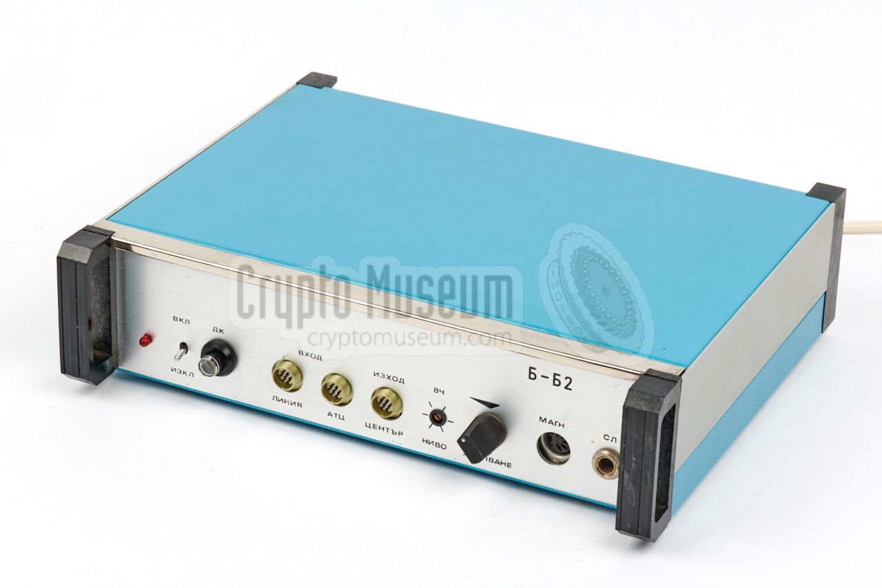
Bugs Stasi Bodil B2 →
The device is housed in a cylindrical aluminium enclosure, that is 47 mm long, has
a diameter of 11 mm and weighs just 12 grams. At the front is a removable cap
behind which a subminiature
BT 1751 buffered microphone
– made in the USA by Knowles 3
– is located.
At the rear are two white teflon wires, by which the device can
be connected to an analogue 'host' telephone line.
The device does not contain a radio transmitter, but instead acts as a parasitic
device on the host (telephone) line. It is a Passive Element that uses the line for transport
of energy and intelligence.
|
|
|
|
Carrier modulation
is used to transport the intercepted audio over the line,
which means that the (analogue) telephone line
can be used as normal, without the bug being overheared during the conversation.
BODIL is remotely activated by injecting a 30 kHz carrier wave into the
phone line.
|
The injection is done at the tapping point, which is commonly somewhere
outside the target area or even outside the building.
As its frequency is above the audible range (supersonic), it can not be
overheard accidentally by the calling parties.
Inside the device, the 30 kHz carrier frequency is multiplied to 60 kHz
and phase-modulated (PM) with room audio, before it is returned to the
line. A Bodil B2 receiver – installed at the tapping point – can be used
to demodulate the 60 kHz signal and retrieve the audio, so that it can
be recorded on tape for analysis and transcription.
|
|
|
|
The protective metal cap at the front end of the device is normally glued in place,
but has been removed here so that we can
check the interior.
According to a test report of June 1981, the East German security service,
the Stasi,
had approved the device for operational use and was going to order
700 bugs, 500 receivers and ~200 leased-line interfaces over the course of
five years [4].
|
|
BODIL is very similar (but not identical) to the
Bulgarian Pchela/Peperuda system
(known by the Stasi
as 33020)
in which a 35 kHz signal is sent and received.
Many thanks to Detlev Vreisleben in Germany for giving us access
to a BODIL transmitter (B1), the matching receiver (B2),
and their technical and historical documentation, obtained from the
archives of the former Stasi
[1].
|
-
Бодил (Bodil) is the Bulgarian word for Thorn.
-
In its capacity as a highly-developed technological country,
Bulgaria was often referred to as the Silicon Valley of the Eastern Bloc
at the time [3].
-
Ironically, many of the Knowles subminiature microphones were developed
during the 1970s with funding from the US
Central Intelligence Agency (CIA).
|
|
A complete BODIL B bugging system consists of the following items:
|
- BODIL B1 (33343-1)
This is the actual bug as shown above. It is powered by a strong 30 kHz
AC signal, sent to it via an analogue telephone line. The device produces
a modulated 60 kHz signal that is sent as a supersonic phase-modulated (PM)
signal via the telephone line to a BODIL-B2 receiver.
BODIL B1 was known by the Stasi
under project number 33343-1.
- BODIL B2 (33343-2)
This is the base station that is connected to the telephone line
at the tapping point.
It contains a 30 kHz signal generator (used for activating the BODIL-B1
bug) and an FM demodulator for supersonic phase-modulated carrier
signals, sent by BODIL-B1.
The receiver – BODIL B2 –was known by the Stasi
under project number 33343-2.
➤ More
|
The diagram below shows how and where the two devices are connected
to the telephone line. At the left is the POTS 1 telephone exchange
from which multiple two-wire cables (here shown in red/blue) are
connected to homes and offices. Somewhere along the way to the
target area, the wires are tapped and the BODIL-B2 receiver is
covertly connected to the line.
This can be done in a patch case, at an underground
cable junction or amplifier, or at the telephone exchange itself.
The BODIL B1 bug is installed in the target area and is connected
to the telephone line, in parallel to the telephone set. By default,
the bug is inactive. In order to activate it, the B2 receiver has
to be switched on and sends out a 30 kHz / 850 mV activation signal.
This signal is rectified into a DC voltage that is just high enough
to power the bug. Inside the bug, it is also doubled to 60 kHz,
which is then phase-modulated (PM) with the ambient sound and
returned to the line.
This process is known as
carrier modulation, and is frequently
used in radio bugs as an audio-masking technique.
As the 30 kHz and 60 kHz signals are relatively far apart,
they can easily be discriminated at the receiving end by using
band filters. Instead of the loudspeaker, it was also possible to use
an additional telephone line to guide the signal to a state security
listening post.
The security service of the former DDR (East Germany)
– the Stasi – also used the
central antenna installation (CAI) of an appartment building as the
transport medium for BODIL. Especially for this application, a
transformer-based modification
was suggested, that allowed the B1 bug
and the B2 receiver to be connected directly to the coaxial cable of the
central antenna system [C]. In such cases
the bug was usually placed inside or near the antenna wall socket
of the TV/radio set.
|
 |
-
POTS = Plain Old Telephone System. Common expression for
the old analogue telephone system.
|
The transmitter, also known as BODIL-B1 or 33343-1, is shown in the image on the
right. It is extremely small – especially considering its age – and can easily
be hidden in the target area.
It was connected to the telephone line,
which means it had to be installed inside or near the telephone set,
or a cable junction box. In case the TV antenna cable was used as a transport
medium, the transmitter was often hidden inside the antenna wall socket
or inside the TV set.
|
|
|
A special matching receiver, known as BODIL-B2 or 33343-2,
was used for remote activation and powering of the transmitter,
and for decoding the returned intercepted audio signal.
It was connected in parallel to the subscriber line and delivered
its audio to a pair of headphones, a (tape) recorder or directly
to a state security monitoring station via a so-called leased line.
➤ More information
|
|
|
The block diagram below shows how the transmitter works. At the far right is
the telephone line from which the 30 kHz activation signal is received
(sent by the receiver). This signal is filtered and then rectified,
creating just enough DC voltage to power the circuit and the microphone.
The 30 kHz is also doubled to 60 kHz and fed to the modulator, where
the amplified sound from the microphone is added, resulting in a
phase-modulated 60 kHz carrier signal that is injected into the
telephone line. The 30 kHz and the 60 kHz signals are way above the
audible range, so that they can pass the cable unnoticed. Yet they are
sufficiently low to pass the existing cables and junction boxes,
especially if the distance between transmitter and receiver is not too large.
The receiver is connected directly to the subscriber line,
as shown at the bottom of the block diagram above.
At the left is the 30 kHz generator that
delivers the activation signal for the bug. The returned modulated 60 kHz signal
is filtered, demodulated, amplified, filtered again and compressed,
and is then fed to the headphones and/or a recorder.
Alternatively, the signal can also be delivered directly to an external
state security listening post via a leased line. The receiver can be
powered from the mains, by internal batteries, or from the (optional) leased
line.
➤ More about the receiver
|
|
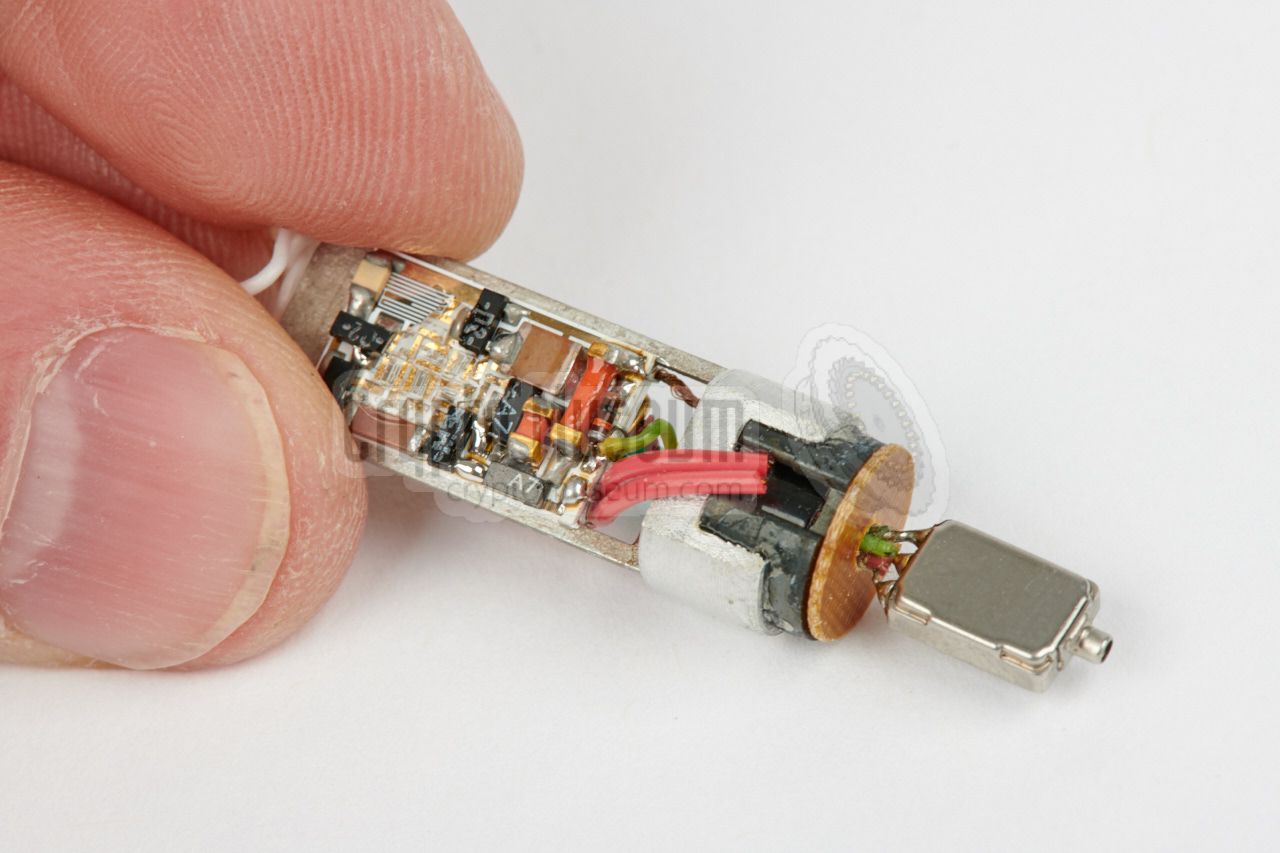
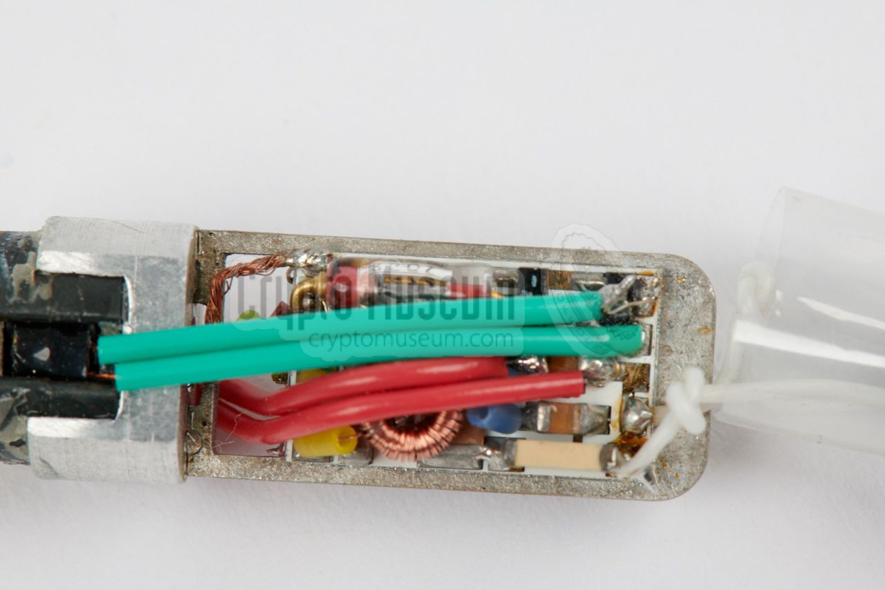
The interior of the BODIL-B1 transmitter is easily accessible. All you have to
do is remove the protective cap from the front end of the enclosure and
carefully pull the Knowles microphone that sticks out below the cap.
If the teflon wires are not blocked, the interior should come out easily.
|
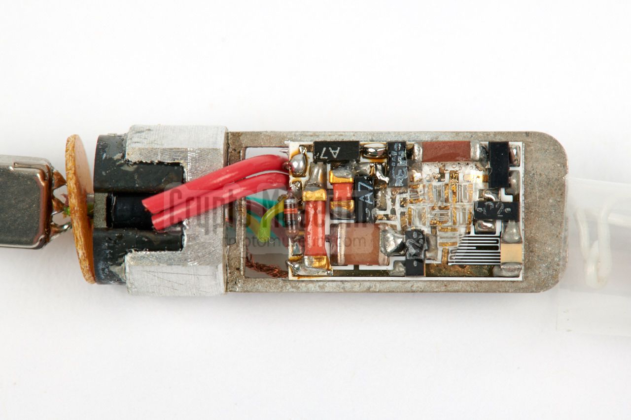
The unit is built on a silver-plated frame and consists of two printed
circuit boards (PCBs), each constructed from a ceramic substrate. One
board holds the power circuit,
whilst the other one holds the
frequency doubler and modulator.
At one end of the frame is a 'large' transformer that is needed
to obtain a galvanic separation between the bug and the telephone line.
On top of the transformer is a
Knowles BT 1751 or 1752 microphone
with a built-in buffer. The three wires of the microphone are guided
through a hole at the center of the cylindrical transformer.
|
|
|
|
Microphones like the Knowles BT 1751 are extremely sensitive and offer a
very good audio quality in the smallest possible package. For that reason
they were commonly used in the hearing aids of the 70s and 80s.
Ironically, they were developed with help from the
Central Intelligence Agency.
|
As part of their miniaturization strategy, the CIA funded much of the
research and development at Knowles at the time.
They did that, of course, with the intention to use them in their own bugs,
but despite Cold War export restrictions, they could not avoid that many of
them found their way into Eastern Bloc countries, commonly under the guise
of local hearing aid manufacturing.
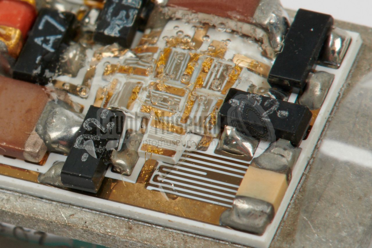
Another point of interest is the sophisticated manufacturing skills
of the Bulgarians at the time. The image on the right shows a close-up of a
series of embedded laser-trimmed resistors.
|
|
|
|
Each resistor is consists of a small rectangular ceramic chip on which
resistive material has been evaporated. Gold-plated contact strips are
present at either end. Seven such resistors are directly bonded to the
ceramic PCB substrate and are fixed in place with a drop of transparent epoxy.
|
Below is the circuit diagram of the transmitter. At the bottom right
is the telephone line (a/b) from which the 30 kHz activation signal
is received. This signal passes transformer Tr1 and is then rectified
in D5-8 into a 60 kHz pulsating voltage. Behind diode D4 this signal
is smoothed by C5 into a stable DC voltage that powers a 3-stage
amplifier consisting of transistors T1-T3.
The voltage for the FET (T4) is delivered by a stabilizing
circuit around D1, D2, D3 and C2.
The signal from the electret microphone (Knowles BT-1751), is amplified
by the 3-stage amplifier (T1-T3) and is then fed to the gate of T4,
which acts as a voltage controlled resistor (much like a potentiometer).
The output of T4 is mixed (modulated) with the pulsating 60 kHz signal
from the bridge rectifier (D5-8) and fed to transformer Tr2,
which injects it into the telephone line (a/b).
The image above shows what the 30 kHz activation signal – produced by the
Bodil receiver – looks like on an oscilloscope. Due to the non-linear
behaviour of the rectifier diodes in the listening device, the signal shows
a slightly distorted pattern which gives away its presence.
|
TF-B (carrier) bugs can be discovered with a special bug finder that can
handle Long-Wave (LW) frequencies, such as the
Scanlock 2000,
the Scanlock ECM
and the OSCOR 5000.
The Stasi checked its own telecommunication and power lines for carrier bugs,
by means of the Capri detector shown in the image on the right. It is suitable
for carrier frequencies from 15 to 410 kHz and can recover the audio.
As Bodil produces a phase-modulated carrier signal, the quality of the audio
produced by Capri is not very good – it is an AM device – but is sufficient
for discovering and locating the bug.
➤ More information
|
|
|
- БОДИЛ Б (BODIL B), Technical manual and operating instructions
Bulgaria, 1979. Original manual in Bulgarian/Russian language.
BStU, 21 pages marked BStU 0178—0199. 1
- Bodil, Beschreibung
DDR, date unknown. Hand-written description (German).
BStU, 10 pages, marked BStU 0223—0232. 1
- Bodil Anpassung, Beschreibung des Vorslages
Hauptmann Bräunig, Suggested modification (German).
Date unknown. BStU, 2 pages marked BStU 0221-0222. 1
- Information Linie B, Nr. 1/86. Kennblatt 'Bodil' 33343-1, 33343-2
Bodil technical specifications (German). January 1986. 6 pages marked BStU. 1
|
-
Document from BStU archives [2],
kindly supplied by Detlev Vreisleben [1].
|
-
Full name: Bundesbeauftragte für die Unterlagen des Staatssicherheitsdienstes
der ehemaligen Deutschen Demokratischen Republik
(DDR) —
Federal Commissioner for the Records of the
State Security Service
of the former German Democratic Republic (GDR) —
officially abbreviated to BStU.
|
|
|
|
Any links shown in red are currently unavailable.
If you like the information on this website, why not make a donation?
© Crypto Museum. Created: Wednesday 02 May 2018. Last changed: Wednesday, 05 November 2025 - 11:38 CET.
|
|

|
|
|


![Collection of Bodil B1 devices at the Stasi in 1985 [D]](img/bodil_stasi_large.jpg)