|
|
|
|
|

|
|
Bugs Stasi
There are two basic versions: one with a built-in
Knowles microphone (33014-10)
and one with an external microphone (33014-11).
Both types are housed in a metal
cylindrical enclosure that is 65 mm long and has a diameter of 12 mm.
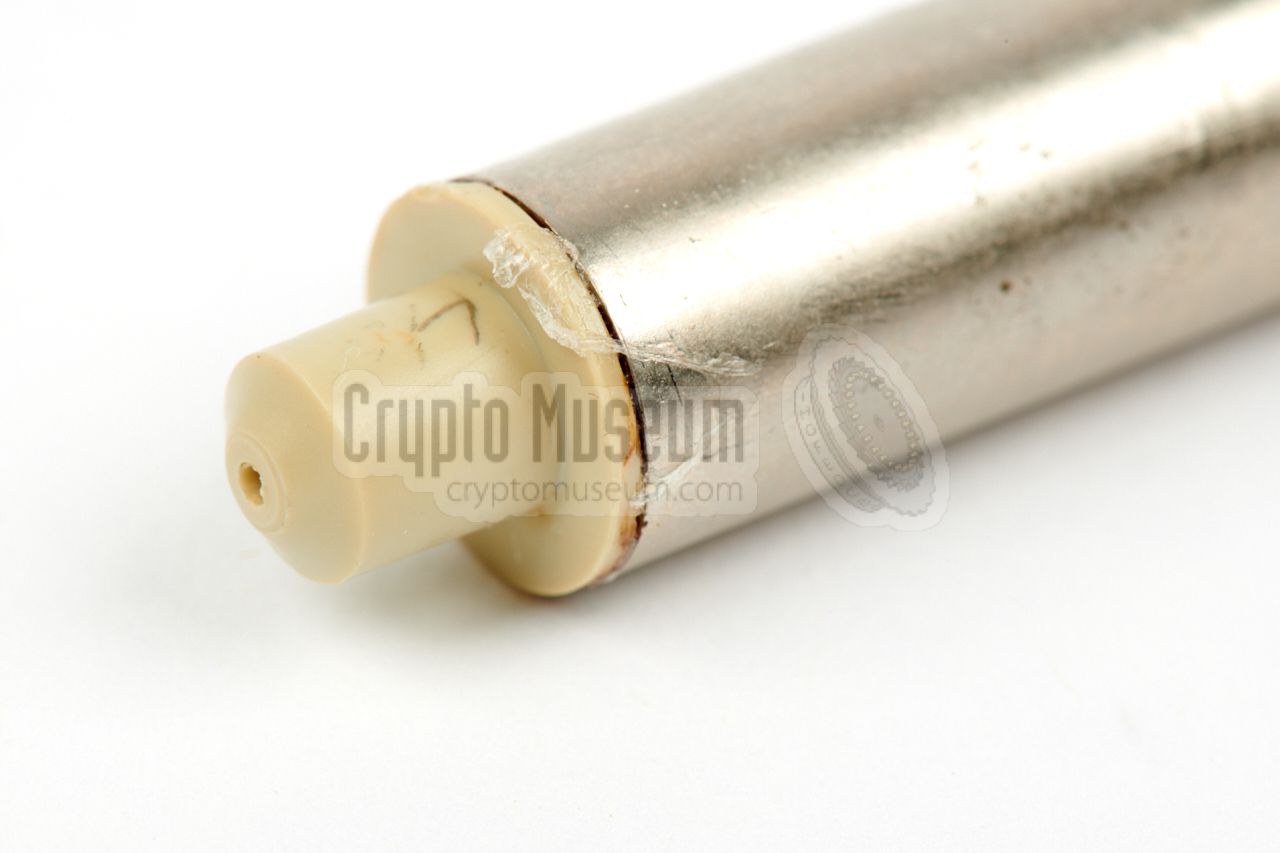
The image on the right shows the 33014-10, which has an internal
Knowles BT-1759 electret microphone.
It can be recognised by the conical plastic tip at the front end. The sound
port of the BT-1759 is located behind the small hole at the centre
of the tip. The 33014-11 version was used with an external
BT-1751 microphone.
|
|
|
Although the device was suitable for various types of domestic wiring,
it was usually connected to a standard analogue telephone line, from which it
also drew its power. Any sound picked up in the
room, was amplitude-modulated (AM) onto an inaudible carrier
and injected back into the telephone line. The audio signal was retrieved
elsewhere in the building (or sometimes outside the building)
with a special receiver,
and relayed to a Stasi monitoring station via a
dedicated line.
According to the original Stasi drawings, development of the device was
started in 1981, with the first devices being available in
1982. It was in production until at least 1986. In March 1985, a warning
was issued for all 33014 devices that had been manufactured until that
date. Although the device was designed to allow three units to be
connected to a single telephone line – using three different carrier
frequencies – it had become clear that this could cause malfunction of
the regular telephone service, which could potentially expose the bugs
and jeopardize the mission.
This was solved by adding an external power supply unit (PSU) in
situations with three bugs [C].
|
The diagram below explains how the 33014 bug was used. At the right is a
regular analogue telephone set which is connected to the telephone exchange
at the left via a subscriber line. The bug is placed in the room under
surveillance and is connected in parallel to the telephone set.
At some point, the subscriber line is tapped and a suitable receiver,
or carrier demodulator, is connected to reveal the intercepted
sound, which is then monitored or recorded locally,
or transferred to a Stasi monitoring station
via a leased line. Note that the tapping point can be inside the target
building, or even outside the building,
with a maximum distance of 5 km.
|
There are two basic versions of the 33014: one with a built-in microphone
– known as the 33014-10 – and one with an external microphone connected by
a short piece of shielded cable – known as the 33014-11. The diagrams below
show a cross-section of both versions.
|
33014-101 With built-in microphone 33014-102 With built-in microphone 33014-103 With built-in microphone 33014-111 With external microphone 33014-112 With external microphone 33014-113 With external microphone
|
33014-1 TF-B Sender (basic device) 33014-10 Version with built-microphone 33014-11 Version with external microphone 33014-9 Microphone capsule for 16 mm PCV pipe 1 TGL 11689 PCV pipe 16 mm Ø (type 100) 2
|
-
Obtained via Stasi department 26/4.
-
Obtained via Stasi department 26/2.
|
|
As the device uses an existing telephone line for the transmission of its
intelligence, the picked-up audio has to be modulated onto a carrier frequency
that is above the human audible range, as otherwise it would interfere with
a regular phone call. In the case of the 33014, three such carrier frequencies,
or channels, were assigned, allowing up to three bugs to share 1
a single line:
|
- 24 kHz
40 kHz ← the one featured here - 104 kHz
|
-
In practice, the number of bugs to be powered from a single telephone
line, was limited to two units, as otherwise the line might be malfunctioning
and the bug might be exposed. When connecting a third bug on the same
line, it had to be powered externally [C].
|
Below is the circuit diagram of the 33014. At the right is the telephone
line (a, b) of which the power is rectified in a rectifier bridge,
consisting of four BAS20 diodes. At the left is the Knowles electret
microphone, which is connected to the input of an USK-14 hybrid modulator
circuit. The output of the USK-14 is injected, or superimposed,
onto the telephone line via TR1, L1 and C4.
Depending on the required carrier frequency, R1, R2 and C4 (purple)
were altered accordingly.
The circuit diagram of the USK-14 ceramic hybrid unit – made by KKWH 1 in
Hermsdorf (DDR) – is currently unknown. It can not be taken down as it
is completely cast in white silicone compound. It is very likely though,
that it holds a Voltage Controlled Oscillator (VCO), identical or very
similar to the CD4046
(from RCA) [5], that was also used in other
designs like the 33010
and 33011.
|
 |
-
KKWH = Kombinat Keramische Werke Hermsdorf. After the fall of the
DDR part of Tridelta, now part of Fraunhofer IKTS (2017) and
LUST Hybrid-Technik GmbH [3].
|
|
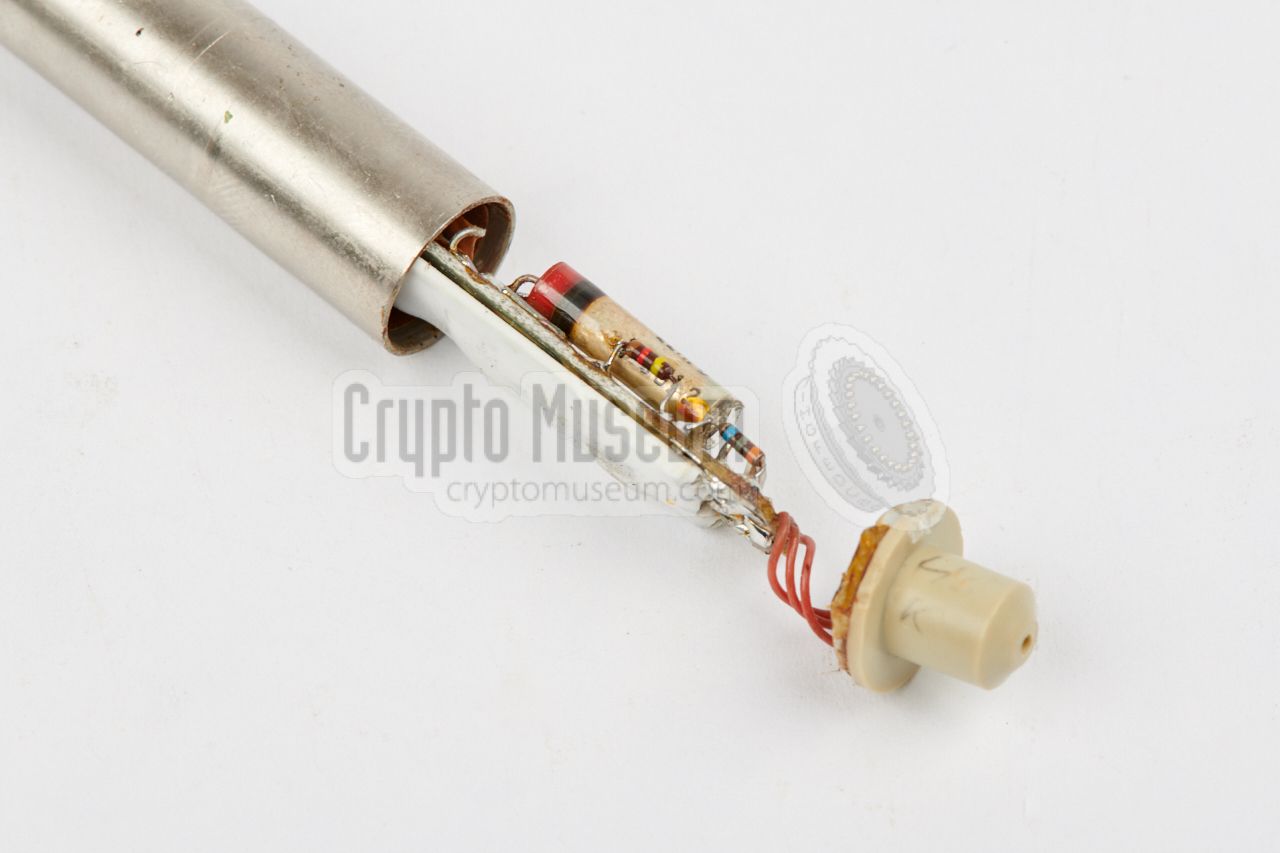
The 33014-10 is housed in a metal tube with an outer diameter of 12 mm. At
the rear, the pipe is
closed with a metal disc
through which the (yellow)
line wires are fed. At the front is a plastic tip that is shaped in such a
way that it forms a sound port for the Knowles BT-1759 microphone.
|
With the 22014-11, the plastic tip is replaced by a plastic disc through
which the microphone lead is fed. The tip and the disc are both held in
place by UHU glue. At the rear end, the yellow ground wire is soldered to the
enclosure. The inside of the tube is isolated with
impregnated paper.
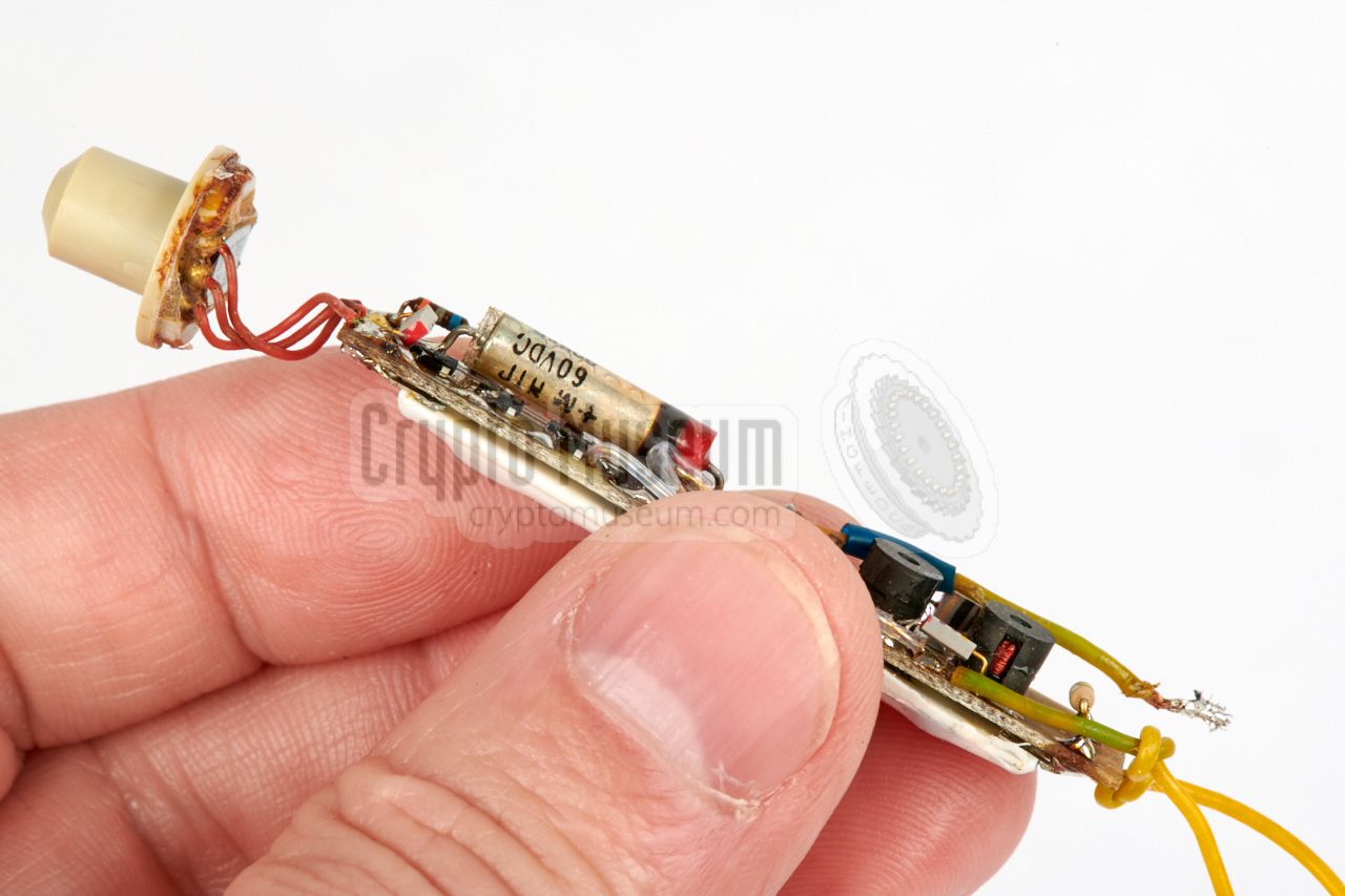
The image on the right shows the front side of the 33014-10, of which the
circuit is partially extracted from the metal tube. At the left is the
plastic tip behind which the Knowles microphone is located. The
top side of the circuit board
(PCB) holds the SMDs and conventional components.
|
|
|
|
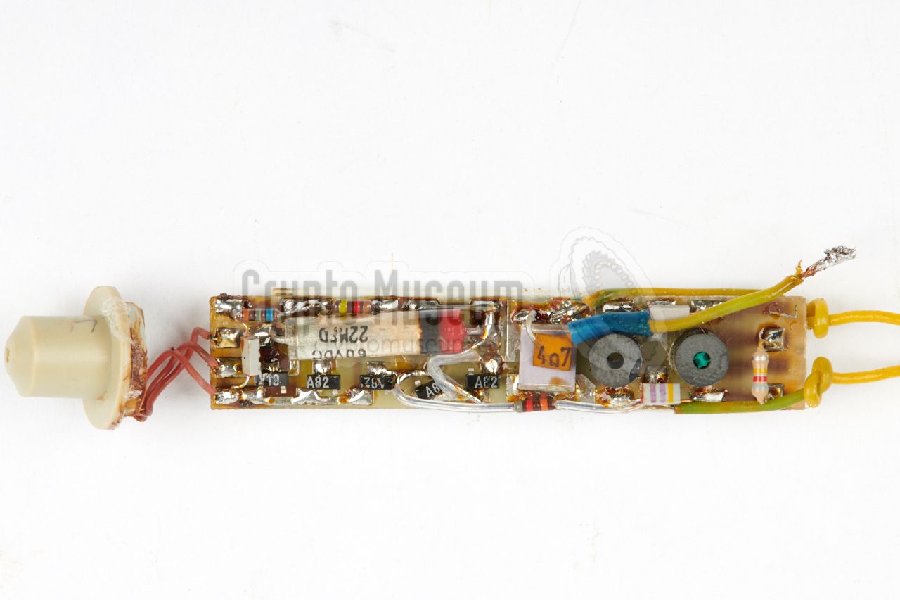
At the bottom side of the PCB
is a ceramic hybrid circuit that holds the
audio pre-amplifier, the Voltage Controlled Oscillator (VCO) and the
voltage stabilizer for the VCO. This hybrid circuit was purpose-built at
Keramische Werke Hermsdorf (KWH, or KKWH) to the specifications of the
Stasi.
It has four solder terminals at either side and its parts are
covered by a white silicone compound.
|
Nevertheless, the contours of some of the parts on the hybrid circuit
are clearly visible through the silicone.
It is certain that a miniature 16-pin chip is located
at the centre of the hybrid and that there are several SMD transistors at
either side of it. This matches with the CD4046-based circuit of — for example
— the 33010 bug
[7].
The image on the right gives a sense of the size, compared to a human hand.
The image also reveals its construction. At the
centre is a thin double sided expoxy printed circuit board (PCB),
with the white USK-14 hybrid at the bottom.
|
|
|
|
All parts that could not be fitted on the hybrid, are at the top side
of the PCB. At the left are three red wires by which the Knowles electret
microphone is connected to the PCB. Note that with the 33014-10, a Knowles
BT-1759 is used. It is mounted perpendicular to the longitudinal axis of
the device, in such a way that its (large) sound port is directly
behind the cone-shaped plastic tip.
|
The diagram below shows the two different electret microphones that were
used with the 33014. The one at the left is a Knowles BT-1759
that was used as the internal microphone of the 33014-10,
fitted perpendicular behind the plastic tip.
The one at the right – a BT01751
– was used with the 33014-11, at the end of a 15 cm long shielded cable.
It has a small tube-style sound port.
The fact that Knowles microphones
were used, is remarkable. Such miniature
microphones were developed and manufactured in the USA, and would not have
been avaiable during the Cold War,
to the countries behind the Iron Curtain.
It is possible though, that they were imported under the pretence that they
were needed for the manufacture of hearing aids. Ironically, the Knowles
sub-miniature microphones were developed during the 1970s and 80s with
help and funding from the US
Central Intelligence Agency (CIA),
who needed them for the production of
their own bugs.
|
TF-B (carrier) bugs can be discovered with a special bug finder that can
handle Long-Wave (LW) frequencies, such as the
Scanlock 2000,
the Scanlock ECM
and the OSCOR 5000.
The Stasi checked its own telecommunication and power lines for carrier bugs,
by means of the Capri detector shown in the image on the right. It is suitable
for carrier frequencies from 15 to 410 kHz and can recover the audio.
➤ More information
|
|
|
Voltage ± 7.5 — ± 60V Current < 500 µA Output 200 mV (into 150Ω) Channels 3 (24, 40 or 104 kHz) Temperature -10 — +45°C Input +85dB max. Audio 300 Hz — 3400 Hz Dimensions 72 x 12 mm Ø Weight 14 grams
|
-
Document obtained from BStU [2] and kindly supplied
by Detlev Vreisleben [1].
|
- Detlev Vreisleben, 33014, technical and historical documentation
Personal correspondence, July — October 2018.
- Bundesbeauftragte für die Stasi-Unterlagen (BStU) 1
Federal Commissioner for the Stasi-Records.
- Fraunhofer IKTS, TRIDELTA im Wandel
Standort-Brochüre Hermsdorf 2017. Prospect (German).
Fraunhofer-Institut für Keramische Technologien und Systeme IKTS, November 2017.
70 pages.
- Robotron Technik, Keramische Werke Hermsdorf (KWH)
Retrieved October 2018.
- Texas Instruments, CD4046 Datasheet
2003. Retrieved January 2014.
- Application note ICAN-6101, The RCA COS/MOS Phase-Locked-Loop,
a versatile building block for micro-power digital and analog applications
October 1972. pp. 614-617.
- Louis Meulstee, 33010 (GDR line bugs VI)
Wireless for the Warrier, Volume 4 Supplement, Chapter 168 v1.00.
Retrieved October 2018.
|
|
-
Full name: Bundesbeauftragte für die Unterlagen des Staatssicherheitsdienstes
der ehemaligen Deutschen Demokratischen Republik
(DDR) —
Federal Commissioner for the Records of the
State Security Service
of the former German Democratic Republic (GDR) —
officially abbreviated to BStU.
|
|
|
|
Any links shown in red are currently unavailable.
If you like the information on this website, why not make a donation?
© Crypto Museum. Created: Sunday 14 October 2018. Last changed: Sunday, 03 May 2020 - 08:01 CET.
|
|

|
|
|