|
|
|
|
|

|
Wired room monitoring bug
Projekt 31550-6 was a miniature audio frequency (AF) 1
covert listening device (bug),
developed in 1977 by the state security service of the former
DDR (East Germany),
the Stasi.
The device was intented for room bugging,
and delivers an LF audio signal onto a 2-wire line that also supplies the
power. The device requires a dedicated line and cannot be used over
switched networks [1].
|
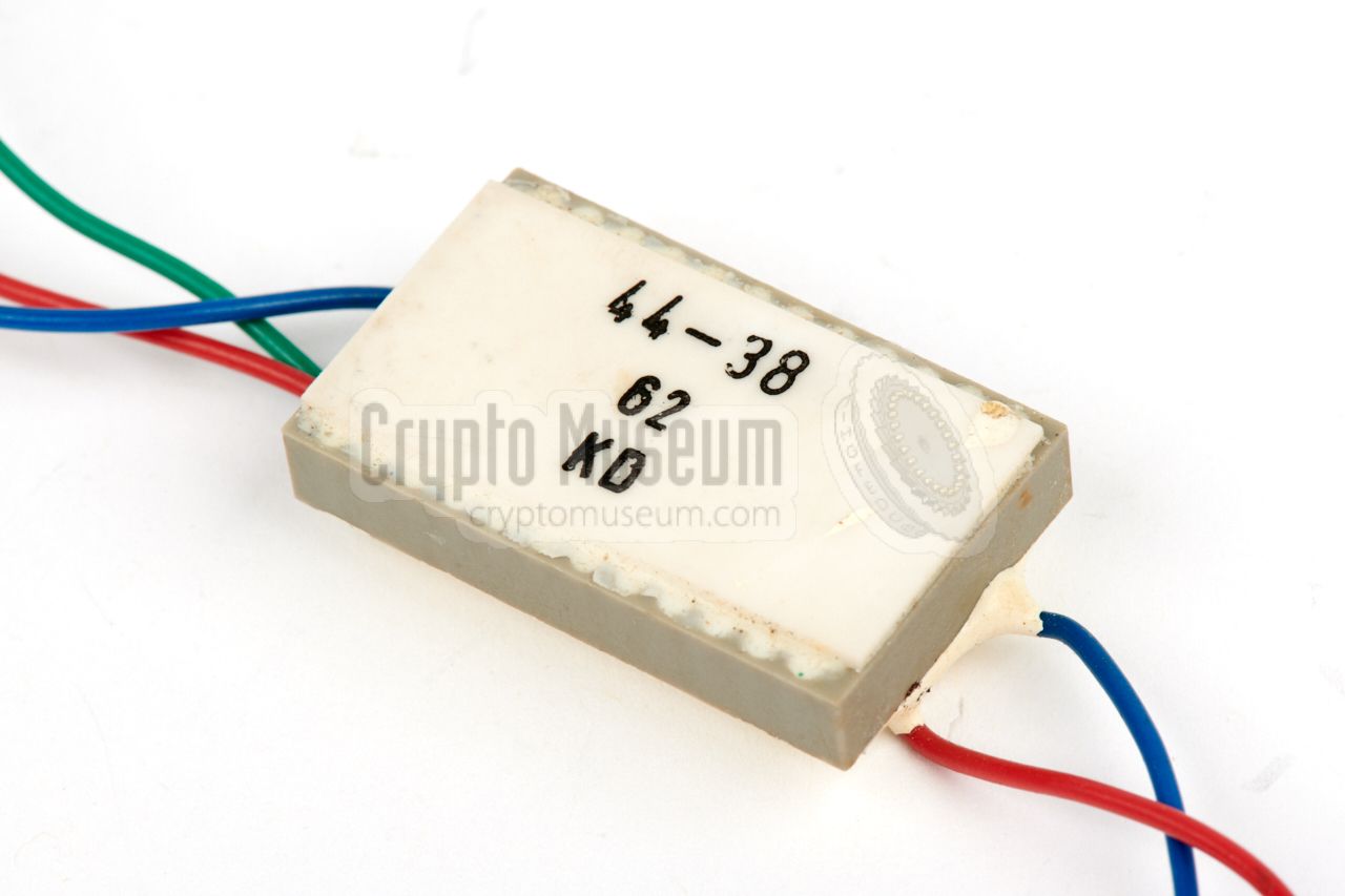
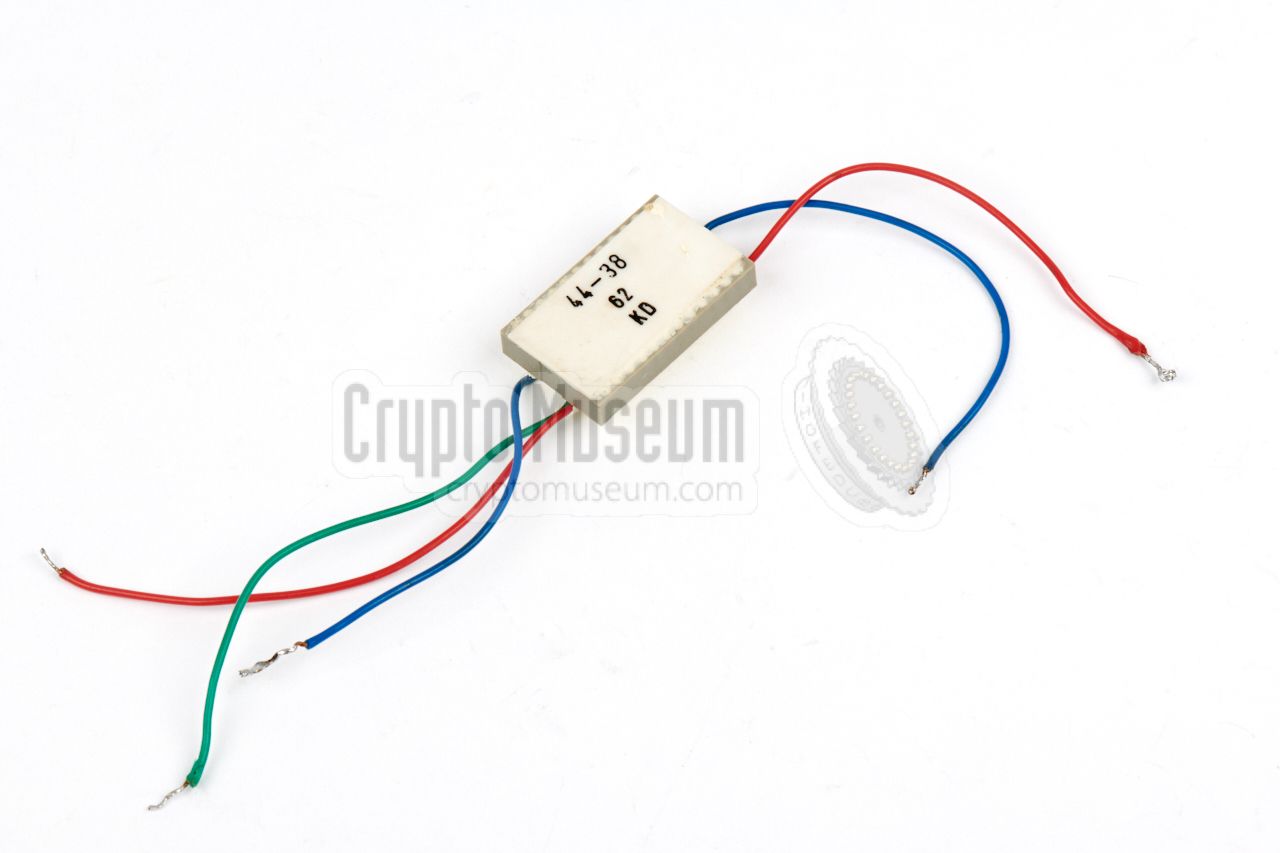
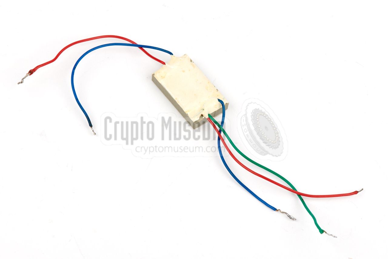
The device is built on a ceramic substrate and is housed in a 24-pin
DIL IC socket, cast in white epoxy. Without the epoxy, it measures 32 x 20 x 5 mm and weighs just 8 grams. At one side are two wires (red and blue) for
connection to the remote listening post. The bug delivers its signal
to these wires and is also powered via them.
At the other side are two or three wires to which an external microphone
should be connected. The image on the right shows a typical 31550-6 with
a 3-wire microphone connection. The red wire supplies 1.5V for
an electret microphone.
|
|
|
|
The 31550-6 is built around the FSA-6 circuit
and is powered by 2.5V.
The numbers 44-38 refer to the circuit diagram, whilst 62 is an
indication of the sensitivity (61 ... 63). At the bottom is the date code KD
which translates to December 1978 [1].
The full circuit diagram is available below.
|
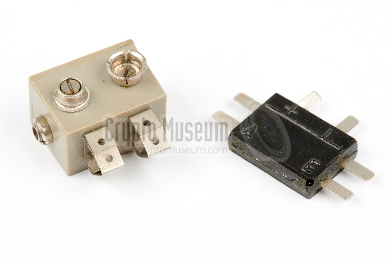
Note that the device was not connected directly to a suitable power source,
but rather via the external black unit shown in the image on the
right. It was located elsewhere in the house and was connected at
the end of the cable, where it
separated the audio signal from the power line.
The item at the left is the power block, that allows a suitable power
source to be connected to the black junction box. It has the terminals
of a standard 9V block battery at the top – for connection of a
3V battery pack – and a socket for connection
of a mains adapter at the side.
|
|
|
|
Devices like the 31550-6 were heavily used by the Stasi for (permanent)
monitoring of homes or offices, in which case they were commonly embedded in
a wall, hidden behind the plastering. In many cases, miniature microphones
from western manufacturers were used, such as the dynamic
Sennheiser MM-301 that
was available in 1971 for US$ 13.50 [3]. The 31550-6 shown here has an extra
wire for powering an electret microphone, and is therefore perfectly suitable
for use in combination with some of the sub-miniature elements from the
American manufacturer Knowles.
|
-
AF = Audio Frequency. German: NF = Niederfrequenz.
|
The diagram below shows a 31550-6 bug ready for use. The actual bug is
visible at the bottom left and is marked 44-38 62 KD. At the right are
two wires (red and blue) for connection of the 2.5V DC power input. A
simple circuit is used to decouple the audio from the power line. At the top
left is the microphone, which can be virtually any type of dynamic or
electret element. It is shown here with a
Shure MC-30, but in practice a
Sennheiser MM-301 was commonly used.
|
Below is the circuit diagram of the FSA-6 circuit that is used at the heart
of the 31550-6. It is basically a 4-stage audio amplifier built around four
identical BCE108B 1 miniature transistors. Power (2.5V) should be applied to
the red terminal at the right via an external 600 Ohm resistor. This voltage
is lowered by the 12k resistor to approx. 1.5V for the first three stages and
the (optional) electret microphone. The last stage (T4) injects the audio
signal into the power line.
The circuit is tolerant to a 15V power supply but will be damaged when
the polarity is reversed. It is built in surface mount technology
(SMT) on a img/302920/003/full.jpg,
which is then placed in a DIL 24 socket,
before casting it in epoxy.
In the above diagram, the red numbers correspond to the pins of the
DIL 24 socket. The device should be connected via the 31530-1 unit shown here:
At the left is the 31550-6 bug with its red (+) and blue (-) wires which
should be connected to the corresponding terminals of the T-shaped black
31530-1 junction box. At the bottom right is the power supply,
which was usually a 31530-2 or 31530-3 unit. At the top right is the audio
output which can be fed to a suitable audio amplifier for recording,
monitoring or distribution.
|
 |
-
The BCE108B is an Eastern Block miniature version of the well-known BC108
transistor. It is basically a universal NPN transistor and is equivalent
to the Western BC848 SMD transistor (in SOT23 enclosure).
|
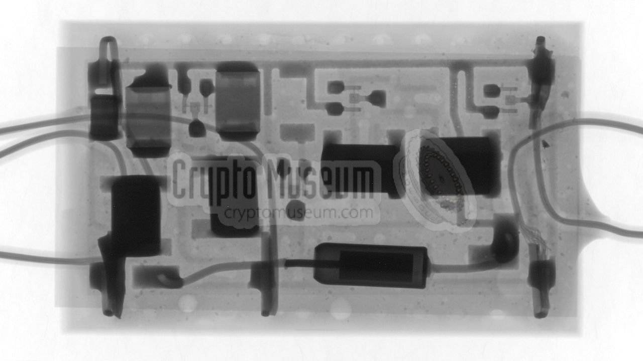
The interior of the 31550-6 can not be inspected easily, as each unit is
cast is white artificial rubber. The only way to see what is inside, is by
making an x-ray image, such as the one below. In the image the ceramic substrate
is clearly visible, along with most of the components. Note that the four
transistors are barely visible (they are the only parts with three legs).
At the bottom is the 47µF capacitor that appeared to be dried out,
which caused a malfunction (see restoration).
|
|
When we received the 31550-6 device featured on this page, it was in
non-working condition. As the circuit is entirely cast in a strong
white epoxy resin, there was virtually no chance of getting access to
the internal parts and, hence, the chances of getting it working again
were slim to none.
|
When we applied 2.5V power to the appropriate terminals via an
improvised coupling circuit
— similar to the 31530-1 junction box
shown in the previous section —
and monitoring the audio output on an oscilloscope, we noticed that
the circuit was exhibiting unwanted oscillations at two different
frequencies: 20 Hz and 80 kHz.
As the input and output voltages were otherwise correct, it seemed likely
that the oscillations were caused by a bad 47µF capacitor on the
secondary power rail (1.5V). It is quite common for such capacitors to
dry out after many years.
|
|
|
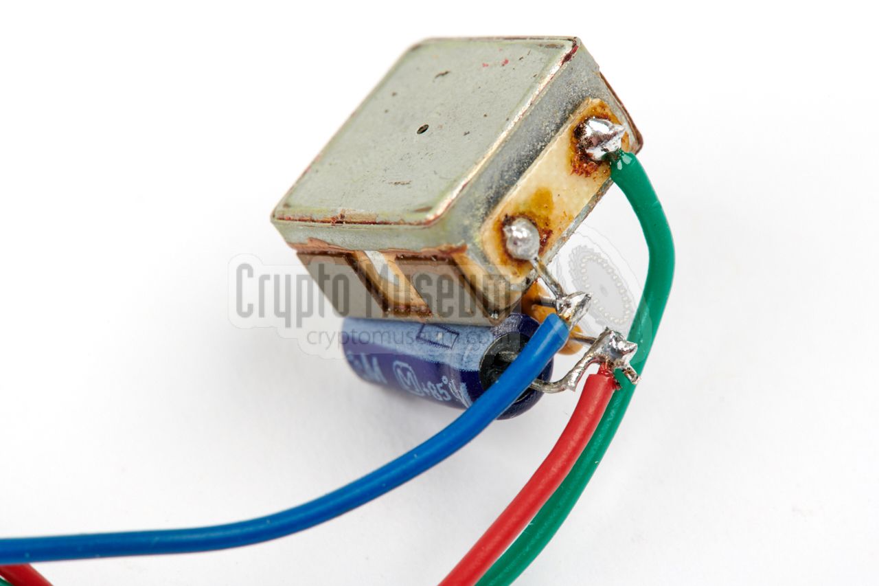
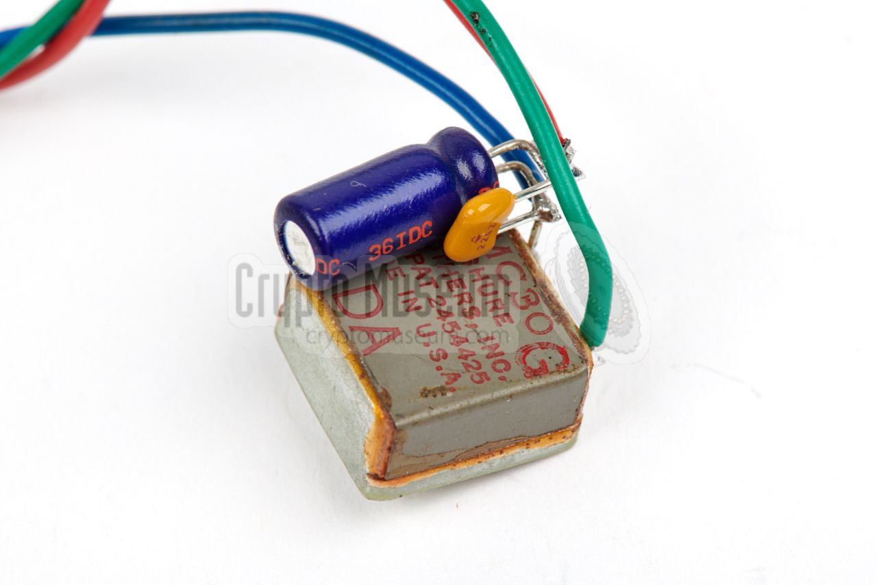
Luckily, the secondary power line is available externally, as it is also
used for powering an electret microphone. Connecting
two external capacitors
of 47µF and 22nF between the 1.5V line and ground, was enough
to get rid of both oscillations and make the bug
fully functional again.
As it is likely that other surviving bugs of this type will exhibit the
same anomaly after all these years, here is how we fixed it for this one.
The two capacitors that were added externally are at the left.
|
The 31550-6 is housed inside the framework of a grey plastic DIL 24 IC socket,
of which some pins are used for the wiring. The diagram below shows the
assignment of the active pins when looking at the device from the top
(text side). All other pins are uncnonnected. Although it is
not possible to access the solder joints (these are cast in epoxy resin),
they can be reached from the top, by pusing a thin sharp measuring pen into
the soft silicone paste that covers the holes.
|
Voltage 2 — 3V DC Maximum 15V Current 1.1mA — 2.0mA Frequency 120 Hz - 10 kHz S/N 30dB Gain 60dB — 69dB Impedance ≥ 40 kΩ Microphone Dynamic or electret Load 600 Ω Temperature -15°C — +45°C Dimensions DIL 24
|
-
Document obtained from BStU [2] and kindly supplied
by Detlev Vreisleben [1].
|
-
Full name: Bundesbeauftragte für die Unterlagen des Staatssicherheitsdienstes
der ehemaligen Deutschen Demokratischen Republik
(DDR) —
Federal Commissioner for the Records of the
State Security Service
of the former German Democratic Republic (GDR) —
officially abbreviated to BStU.
|
|
|
|
Any links shown in red are currently unavailable.
If you like the information on this website, why not make a donation?
© Crypto Museum. Created: Saturday 16 June 2018. Last changed: Wednesday, 05 November 2025 - 11:36 CET.
|
|

|
|
|


