|
|
|
|
|

|
|
Racal MA-4235
Ruggedized thermal printer
The MA-4133 is a compact military ruggedized thermal printer for use with
message equipment, developed and built in the late 1970s by
Racal Datacom Ltd. (UK).
It was designed especially for printing incoming messages on the
Racal MA-4231 automatic morse receiver, but was also used
with other message equipment and cipher machines.
Also known as NSN 5865-99-539-6085.
|
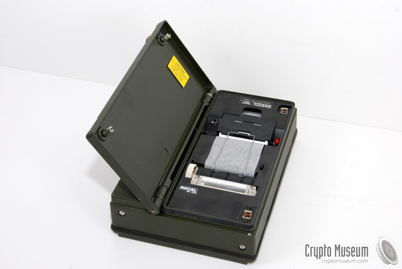
The device was typically used with the MA-4230 morse encoder
and the MA-4231 decoder, and is roughly the same size as both
these units together. It allowed them to be mounted size-by-size inside a
Samsonite briefcase of the era.
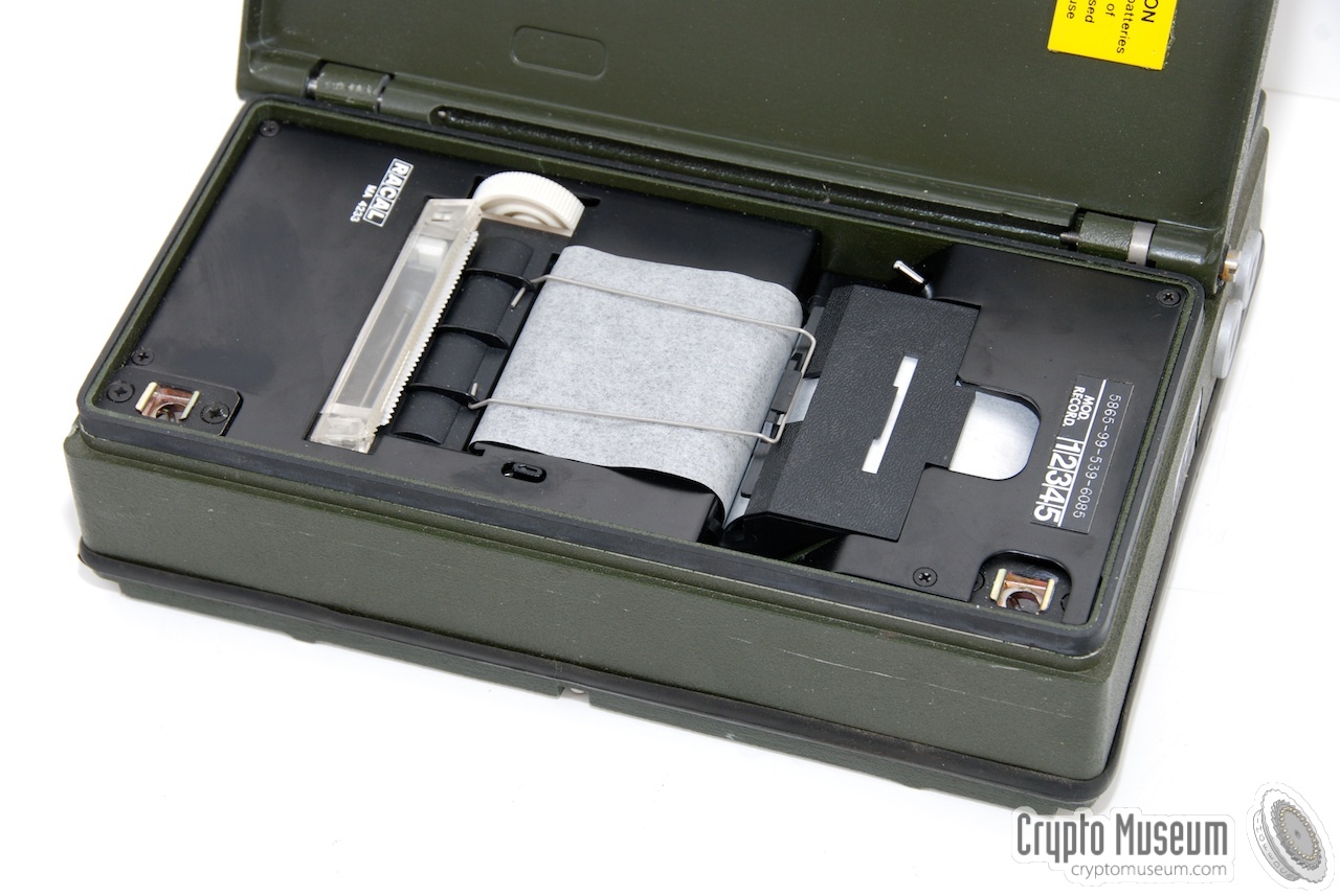
The unit is housed in a green die-cast aluminium enclosure that
measures 232 x 170 x 63 mm and weighs ~3 kg.
Power is provided by an internal rechargeable battery that is charged
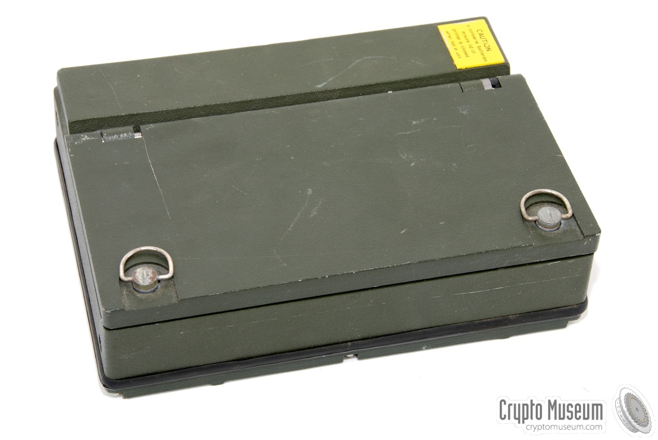
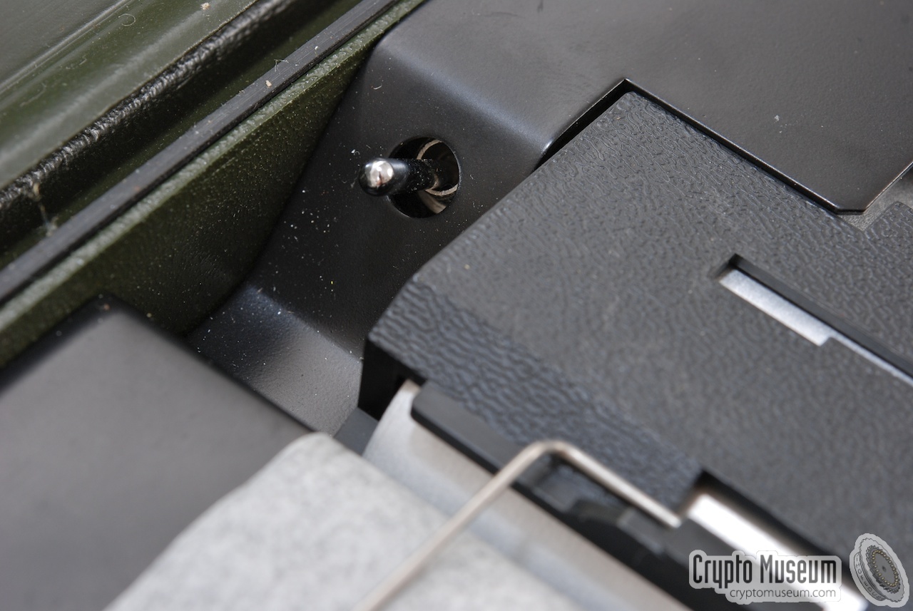
from an external power supply. It has a lid at the top that
is constructed in such a way that it cuts the power supply automatically
when it is closed.
|
|
|
|
The device has a serial interface with 5V TTL level signals, and accepts
5-bit data (ITA2)
as well as 8-bit data (ITA5, ASCII)
at speeds between 50 and 9600 baud, configurable with internal DIP switches.
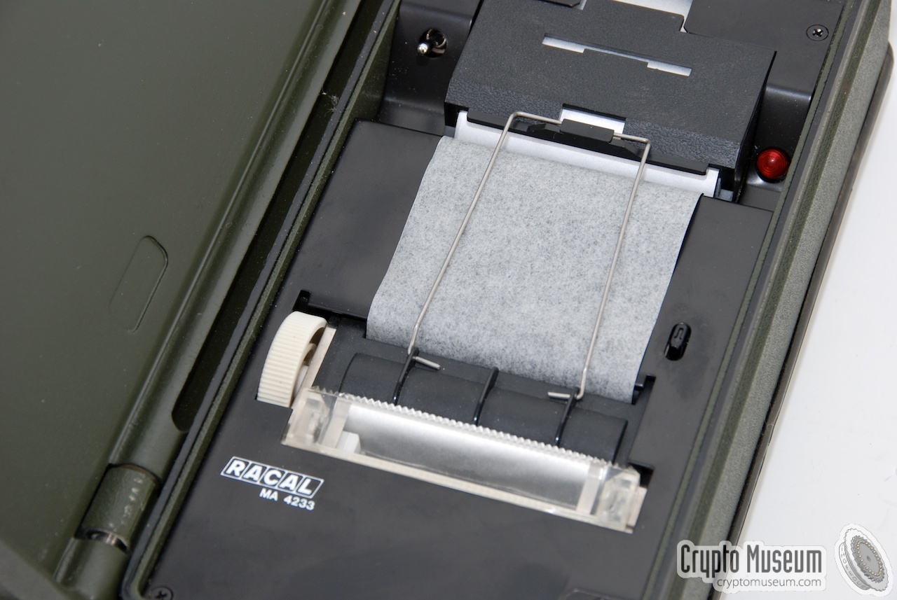
Latin characters are printed in a 5 × 7 matrix on 60 mm wide metallic electrosensitive thermal paper (~30 m).
Text is printed per line upon receipt of an EOL character or when
the unit is idle after receipt of a message. It can print up to 31 characters
on a sigle line at 60 cps. This means that it can print
~200 lines of text per minute.
For other languages, such as Farsi and Arabic, a variant with a 7 × 7 matrix
was available. The Arabic version is known as MA-4233A.
|
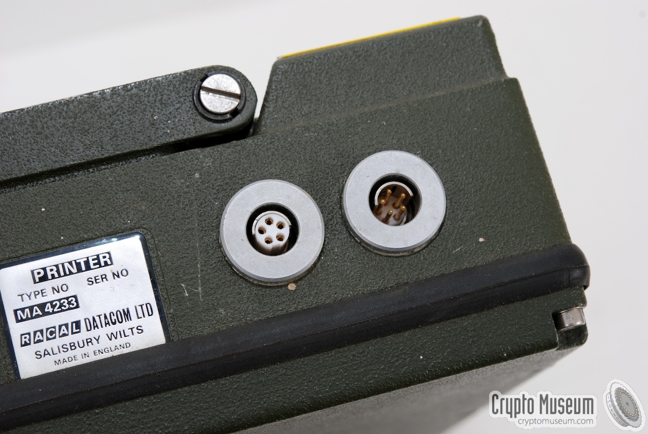
The MA-4233 printer has two 5-pin Fischer sockets at its right side.
The leftmost one (female) is the serial data input. It is designed for a
1-on-1 connection with the Racal MA-4231 morse receiver.
|
| |
Looking into the Fischer sockets
|
The pins of these sockets are numbered from 1 thru 5, but note that this
numbering is different from the numbering inside the matching plug!
The pins are wired according to the wiring diagram below. The colours specified
in the table are the ones used in the original Racal cables.
Connection to the MA-4231 (left)
|
| Pin | Name | Colour | Description |
|
|
| 1 | n.c | - | No connection |
| 2 | DATA | Red | Serial data input, from MA-4231 |
| 3 | READY | White | Printer ready (input) |
| 4 | Power | Yellow | Power supply or battery charger (+ 11 to 30V) |
| 5 | GND | Green | Common connection (ground) |
| Shield | GND | Braid | Common connection (ground) |
|
A suitable male connector for this socket is Fischer S103 A054-130+.
Connection of a battery charger (right)
|
| Pin | Name | Colour | Description |
|
|
| 1 | n.c | - | No connection |
| 2 | n.c | - | No connection |
| 3 | n.c | - | No connection |
| 4 | Power | Yellow | Power supply or battery charger (+ 11 to 30V) |
| 5 | GND | Green | Common connection (ground) |
| Shield | GND | Braid | Common connection (ground) |
|
A suitable female connector for this socket is Fischer S103 Z054-130+.
|
The unit is powered by a set of internal rechargeable NiCd batteries that can
be charged via any of the connections at the right. Please note that the
batteries must be fully charged before the unit can be operated, even
when an external voltage is supplied.
Also note that the batteries in most of these surplus devices, are either
dead or worn-out, even when the device (and in some cases the battery)
looks brand new. These units were built around 1980 and its battery
life time has long expired. Whithout a healthy battery, the unit can not
be operated properly.
Inside the MA-4233 are two different batteries. One consists of 2 VARTA
12 V NiCd packs connected in series (24V total). The other battery is a
6V high-current battery. When these batteries start leaking, they may
cause permanent damage to the PCB and the internal connectors.
The charging voltage is supplied to the same pins of the sockets on all
devices of the MA-4230 family.
These pins (4 and 5) are all interconnected, allowing a
battery charger or external power supply to be connected anywhere in the
chain. Generally though, a battery charger would be connected to the printer
(if present). When connected to a suitable radio, power would generally
be supplied by the radio (connected to the MA-4230 unit).
Please note that, when using an external power source for charging the
batteries (e.g. power taken from a transceiver),
the battery charger should be disconnected.
|
|
The MA-4233 is housed in a ruggedized die-cast aluminium case with a lid at
the bottom. The lid is held in place by 6 hex-head bolts that are easily
removed. All electronics are contained on a single PCB. Once the lid is
removed, the solder side of the PCB is revealed.
|
The PCB covers the entire bottom section of the printer.
By removing a couple of bolts at the bottom, the PCB can be removed.
Three green connectors are used to connect the PCB to the thermal printer unit,
the batteries, the power switch and the two Fischer connectors.
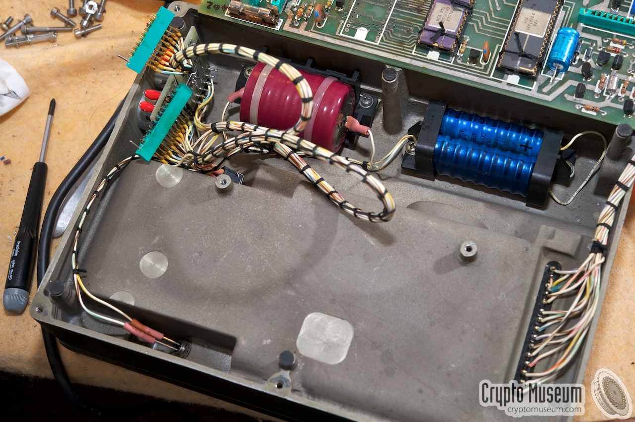
The batteries are mounted in the top section of the
die-cast case. This is rather unfortunate, as old batteries are likely to
leak their chemical substance onto the PCB, causing permanent damage.
Two battery packs are present:
one for the 6V and
one for the 24V power supply.
|
|
|
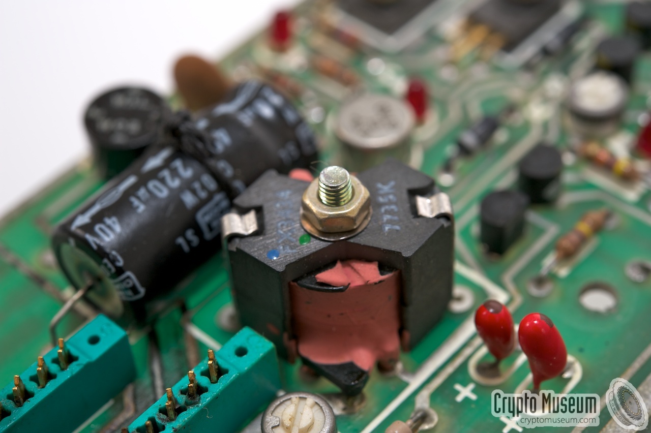
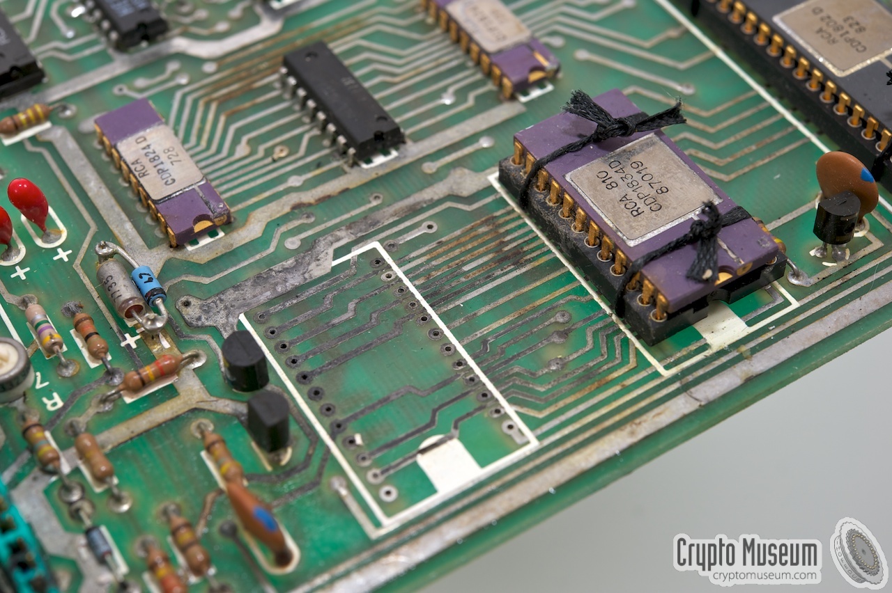
The images below show the interior of the MA-4233 and the layout of the PCB.
The rightmost image shows how the PCB can be
damaged by leaking batteries.
|
|
|
Connecting the printer to an MA-4231
|
|
|
|
The MA-4233 is a universal thermal printer, that can be connected to a wide
variety of devices, including (portable) PCs
and the MA-4231 automatic morse receiver. The printer has a
standard RS-232 compatible serial port and can be configured for a wide
range of baud rates.
|
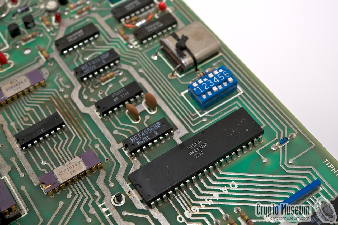
Baud rate and word format can be configured with 6 DIP switches
towards the edge of the PCB. Unfortunately, the PCB has to be removed
before the settings of the DIP switch can be changed.
The first four switches (1, 2, 3 and 4) are used for selection of the
baud rate.
Switch 5 is used for selecting the word length (5 or 8 bits),
whilst switch 6 is used for selecting the number of stop bits.
Unlike the MA-4231 morse decoder, the printer does not support parity.
A table for setting the DIP switches is present on the inside of the bottom lid.
|
|
|
The table below shows how the DIP switches should be set for a particular
baud rate. Please note that the top row of the blue DIP switch is marked
with a + sign. The table shows the position of the notch on the row with the
+ sign, which is either up (U) or down (D). The DIP switches in the
above image are set up for 1200 baud 8N1.
|
Device Printer Type Dot matrix, thermal Purpose Printing text messages in the field Manufacturer Racal Model MA-4233 Country UK Year ~1979 Language Latin matrix 5 × 7 Power Internal NiCd batteries Charge 12-30V DC / 80 mA Paper Metallic electrosensitive, 60 mm wide, ~30 m long Interface Serial, 5V TTL Format ITA2, ITA5 (ASCII) Baudrate 50, 75, 110, 134.5, 150, 200, 300, 600, 1200, 1800, 2400, 4800, 9600 Stop bits 1, 1.5, 2 Temperature -10°C to +55°C Storage -10°C to +70°C Dimensions 232 × 170 × 63 mm Weight 3 kg
|
|
|
|
Any links shown in red are currently unavailable.
If you like the information on this website, why not make a donation?
© Crypto Museum. Created: Thursday 26 August 2010. Last changed: Wednesday, 05 November 2025 - 11:27 CET.
|
 |

|
|
|
| |