|
|
|
|
|

|
|
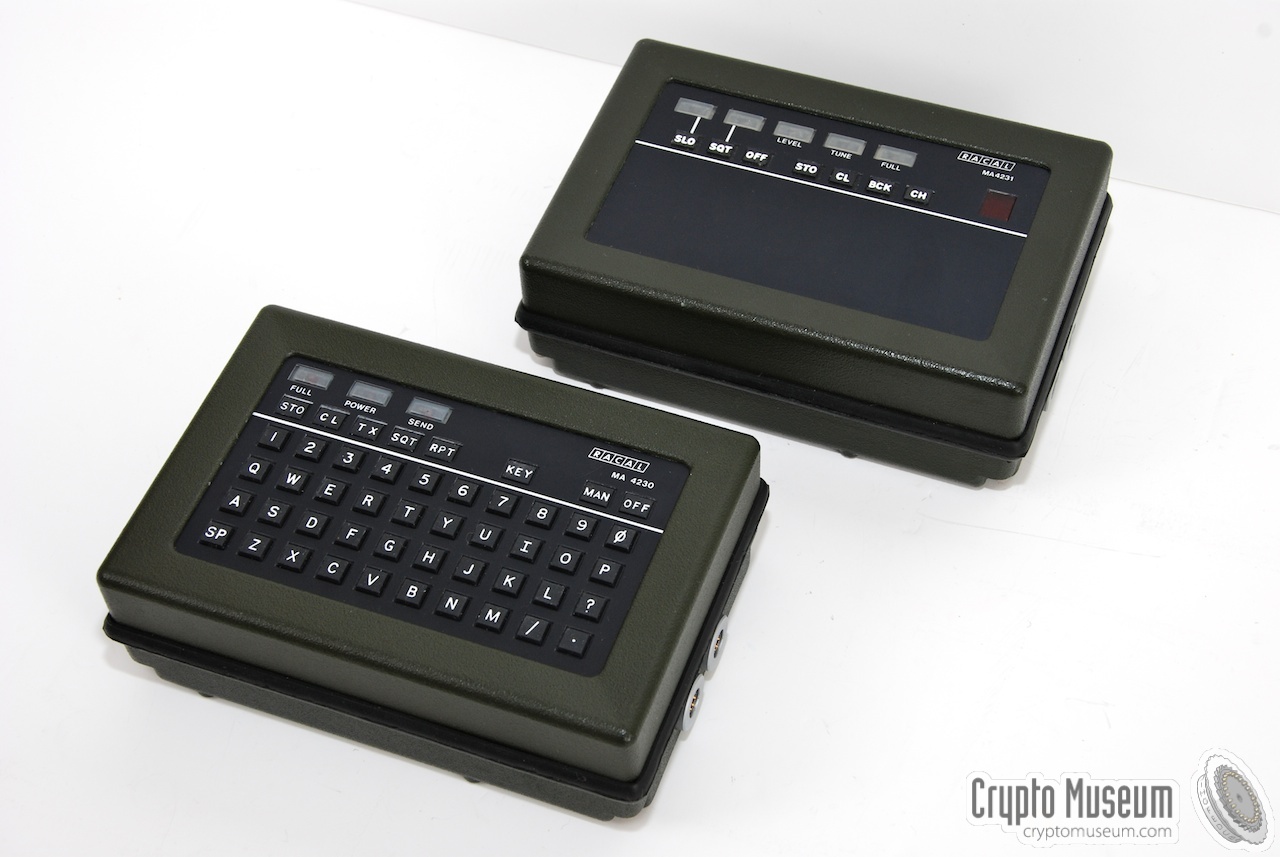
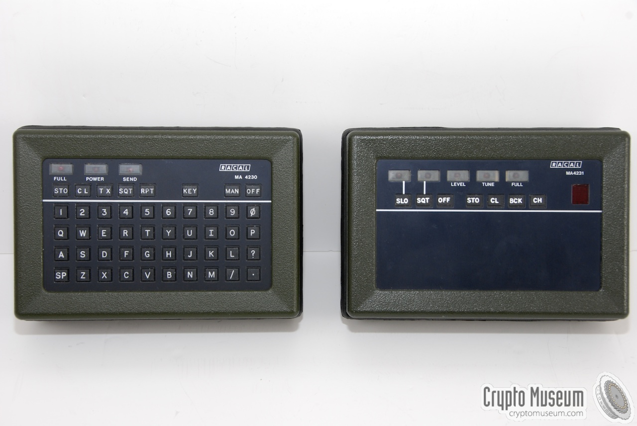
Racal MA-4235 ← MA-4230
Morse burst decoder
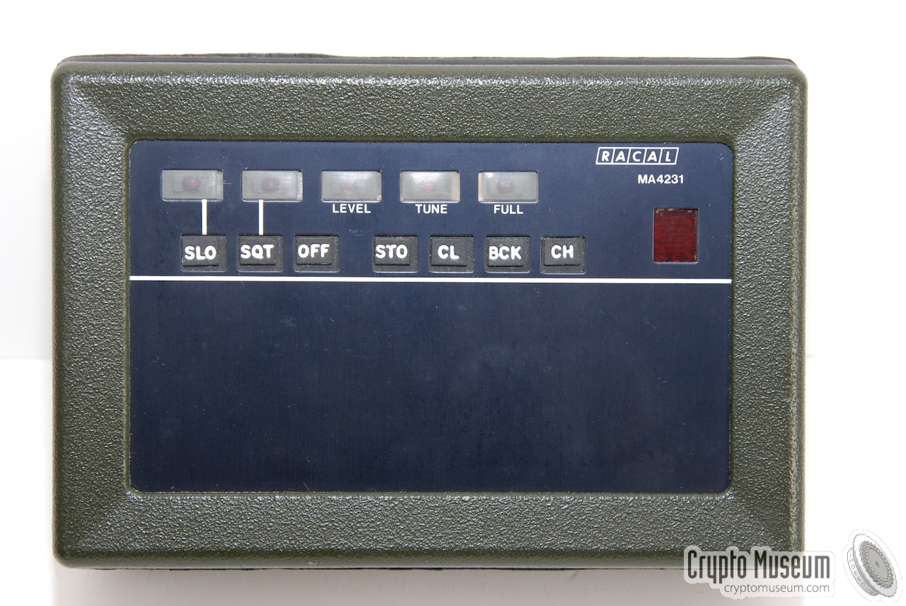
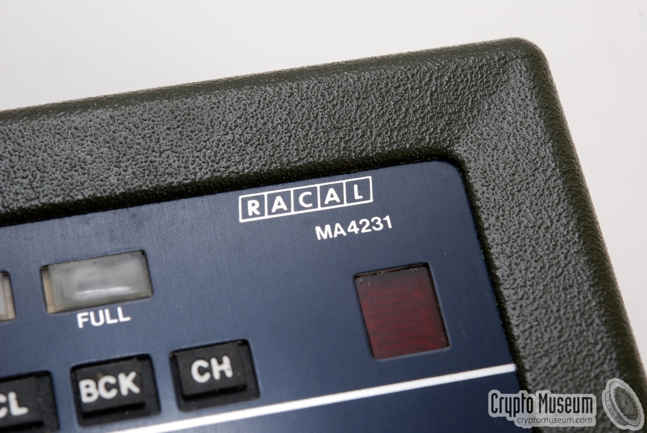
The MA-4231 was an automatic morse decoder, designed and build by
Racal Datacom Ltd. (UK) around 1977.
It messages, sent in morse code
at various speeds, to be recorded
and played back. It was part of a family of devices,
including a morse burst encoder, a printer and various power sources.
It was intended for use as part of a spy radio set and by Special Forces (SF).
|
The image on the right shows a typical MA-4231 unit.
It is housed in a case that is identical to that of the
MA-4230, albeit with far less keys on it.
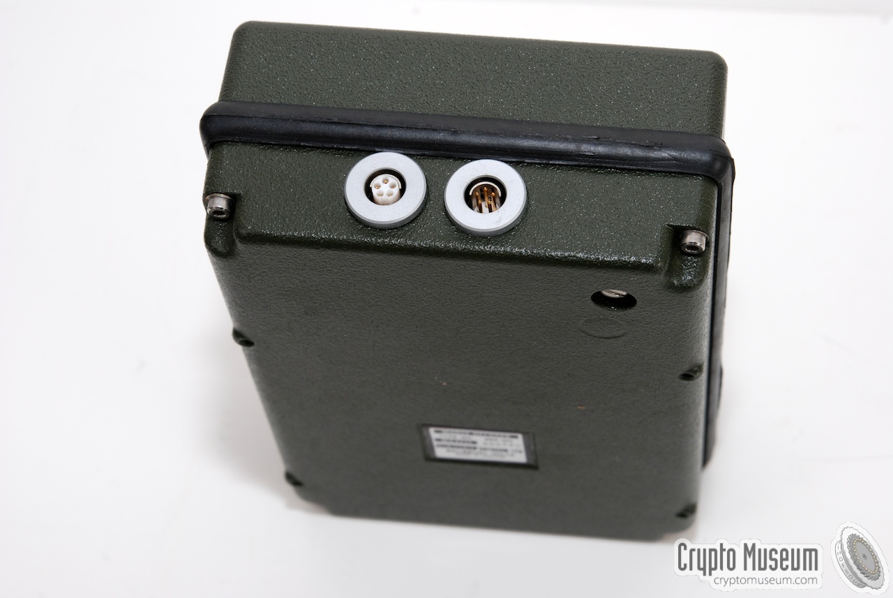
It has two sockets at its right,
allowing it to be connected to the MA-4230 burst encoder and to an
(optional) printer or teletype unit.
The unit is powered by an internal rechargeable battery, that allows the
receiver to be used continuously for approx. 10 hours withut recharging.
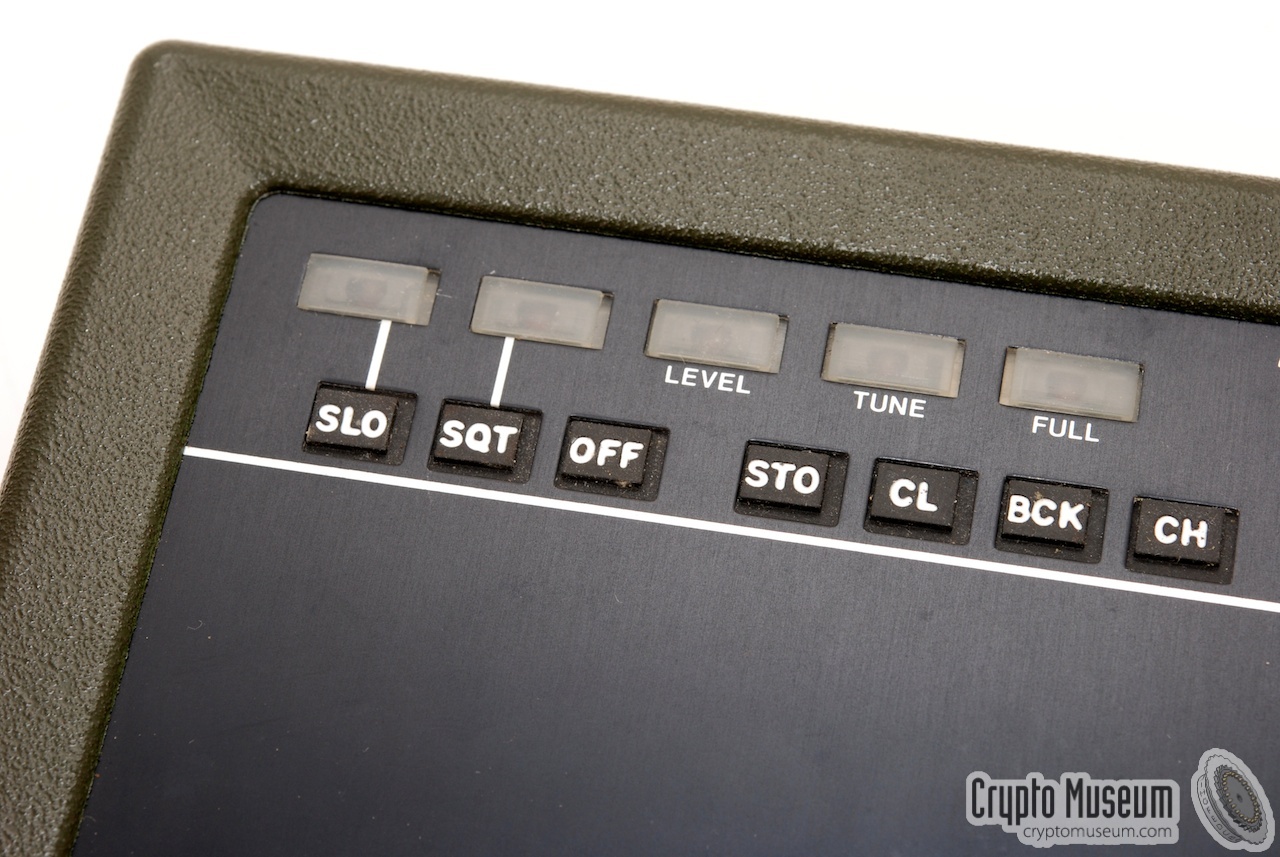
It can receive morse code
signals at normal speed (10-30 wpm) and at
high speed (30-160 wpm). This is called Squirt Mode.
|
|
|
When receiving morse code
signals, the MA-4231 needs at least 32 code elements
to stablish the transmission speed. This means that the sender has to include
a preample, containing at least 4 dots, 4 dashes, 4 inter-unit spaces and
4 letter spaces, at the beginning of a message. These characters should then
be considered lost.
When using the MA-4231 in combination with an
MA-4230 burst encoder at the other end,
the units are synchronised by a pilot tone sent by the MA-4230 at
the start of each message. Once synchronized by this tone, no characters will
be lost.
During reception, the received morse code
signal is decoded and shown on the
red dot-matrix display in the upper right corner, one character at a time.
The message is also stored in the internal memory, so that it can be read
back later using the CH and BCK keys.
The output can also be sent to a complementary printer,
such as the MA-4233.
If such a printer is connected, the received message will not be shown
on the dot-matrix display and can not be read back using the CH and BCK keys.
|
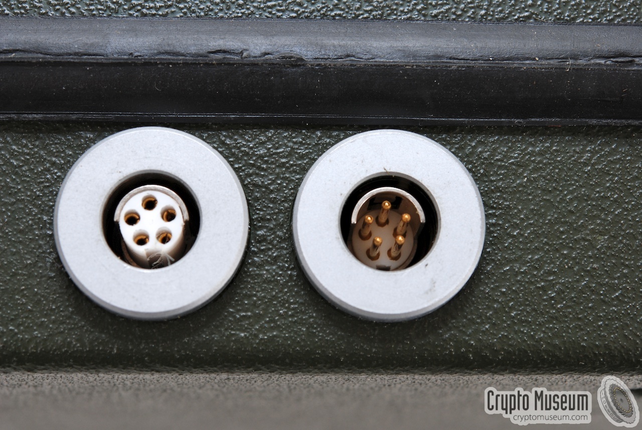
The MA-4231 has two 5-pin Fischer sockets at its right side.
The rightmost socket (male) is used for connection to the MA-4231 morse encoder,
whilst the leftmost one (female) allows a printer or a teletype unit to be
connected.
|
| |
Looking into the Fischer sockets
|
The pins of these sockets are numbered from 1 thru 5, but note that this
numbering is different from the numbering inside the matching plug!
The pins are wired according to the wiring diagram below. The colours specified
in the table are the ones used in the original Racal cables.
Connection to the MA-4230 (right)
|
| Pin | Name | Colour | Description |
|
|
| 1 | RX | Blue | Audio from receiver (keyed tone) |
| 2 | TX | Red | Keyed tone from MA-4230 (monitor) |
| 3 | PTT | White | PTT input (controlled by transceiver or MA-4230) * |
| 4 | Power | Yellow | Power supply or battery charger (+ 11 to 30V) |
| 5 | GND | Green | Common connection (ground) |
| Shield | GND | Braid | Common connection (ground) |
|
A suitable female connector for this socket is Fischer S103 Z054-130+.
*) The operation of the PTT signal at pin 3, is determined by a link on the
Keyer board inside the MA-4230.
When the link is open, pin 3 is configured as
a PTT output. During a tranmission, pin 3 is held low (GND) for the duration of
the message plus 1.5 sec.
When the link is closed, pin 3 acts as a KEY output (active low), synchronised
with the tones at pin 2 [A].
Connection to a printer (left)
|
| Pin | Name | Colour | Description |
|
|
| 1 | n.c. | - | No connection |
| 2 | OUT | Red | Serial data out |
| 3 | READY | White | Printer ready (input) |
| 4 | Power | Yellow | Power supply or battery charger (+ 11 to 30V) |
| 5 | GND | Green | Common connection (ground) |
| Shield | GND | Braid | Common connection (ground) |
|
A suitable male connector for this socket is Fischer S103 A054-130+.
|
The unit is powered by an internal rechargeable NiCd battery that can
be charged via any of the connections at the right. Please note that the
batteries must be fully charged before the unit can be operated, even
when an external voltage is supplied.
Also note that the batteries in most of these surplus devices, are either
dead or worn-out, even when the device (and in some cases the battery)
looks brand new. These units were built around 1980 and its battery
life time has long expired. Whithout a healthy battery, the unit can not
be operated properly.
The charging voltage is supplied to the same pins of the sockets on all
devices of the MA-4230 family.
These pins (4 and 5) are all interconnected, allowing a
battery charger or external power supply to be connected anywhere in the
chain. Generally though, a battery charger would be connected to the printer
(if present). When connected to a suitable radio, power would generally
be supplied by the radio (connected to the MA-4230 unit).
Please note that, when using an external power source for charging the
batteries (e.g. power taken from a transceiver),
the battery charger should be disconnected.
|
|
The MA-4231 allows a variety of printing devices to be connected to the
leftmost Fischer connector, ranging from 5-bit teletype
devices (ITA2) to modern telex units and printer with an 8-bit serial
interface (ITA8). A set of jumper wires on the Interface Board of the
MA-4231, allow the data format to be configured. The following can be set:
|
- Baud rate (50, 75, 110, 134.5, 150, 200, 300, 600 or 1200 baud)
- Parity (on/off, even/odd)
- Word length (5-bits or 8 bits)
- Stop bits (1, 1.5 or 2 bits)
|
The baud rate can be configured by adding or removing 4 wire links on the
interface board. All other options are selected by links in the form of
10K and 100K resistors. The drawing below shows the position of the various
links on the interface board.
The MA-4231 supports 9 different baud rates that are selected by 4 wire links
on the interface board. The links are numbered S0 (top) to S3 (bottom).
The table below shows the relation between the wire links and the baud rate.
A black dot indicates the presence of a wire link.
Please note that when a printer is connected to the MA-4231, the message
can not be read from the message buffer manually using the CH and BCK keys.
|
|
The MA-4231 is housed in a ruggedized die-cast aluminium case, similar to that
of the MA-4230 burst encoder. The case consists of 2 halves
(shells), with a rubber gasket in the middle. The two shells are kept
together by 4 hex-head bolts at the bottom.
|
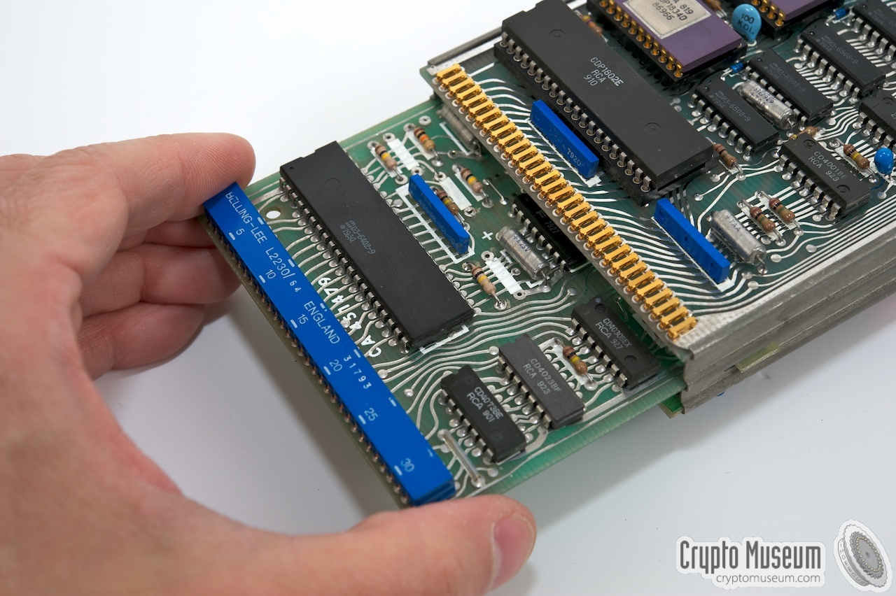
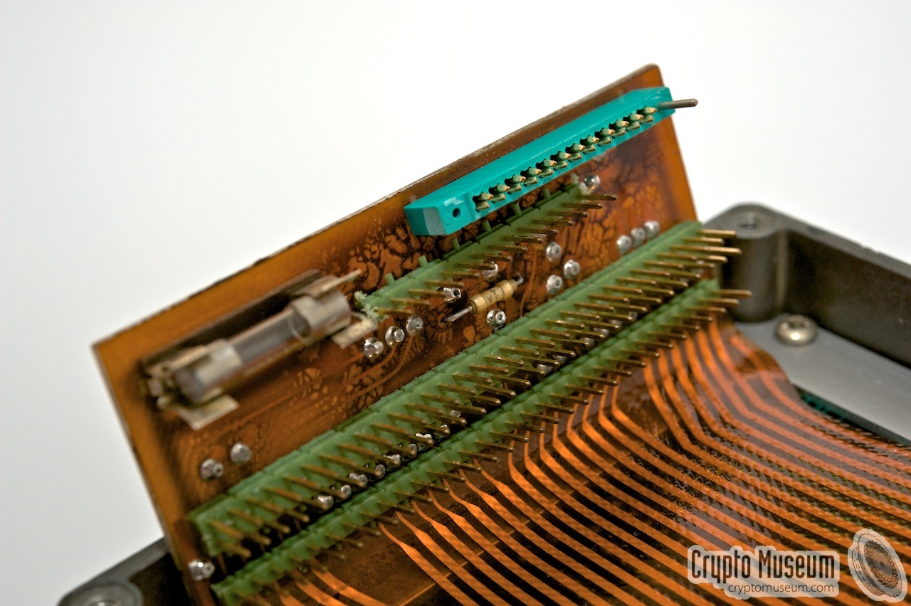
After separating the two halves of the case, the interior is revealed.
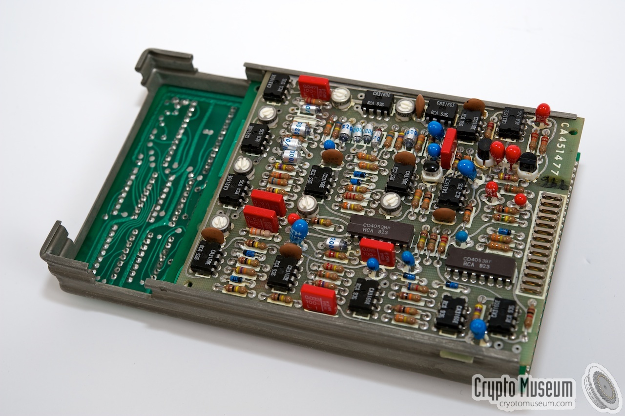
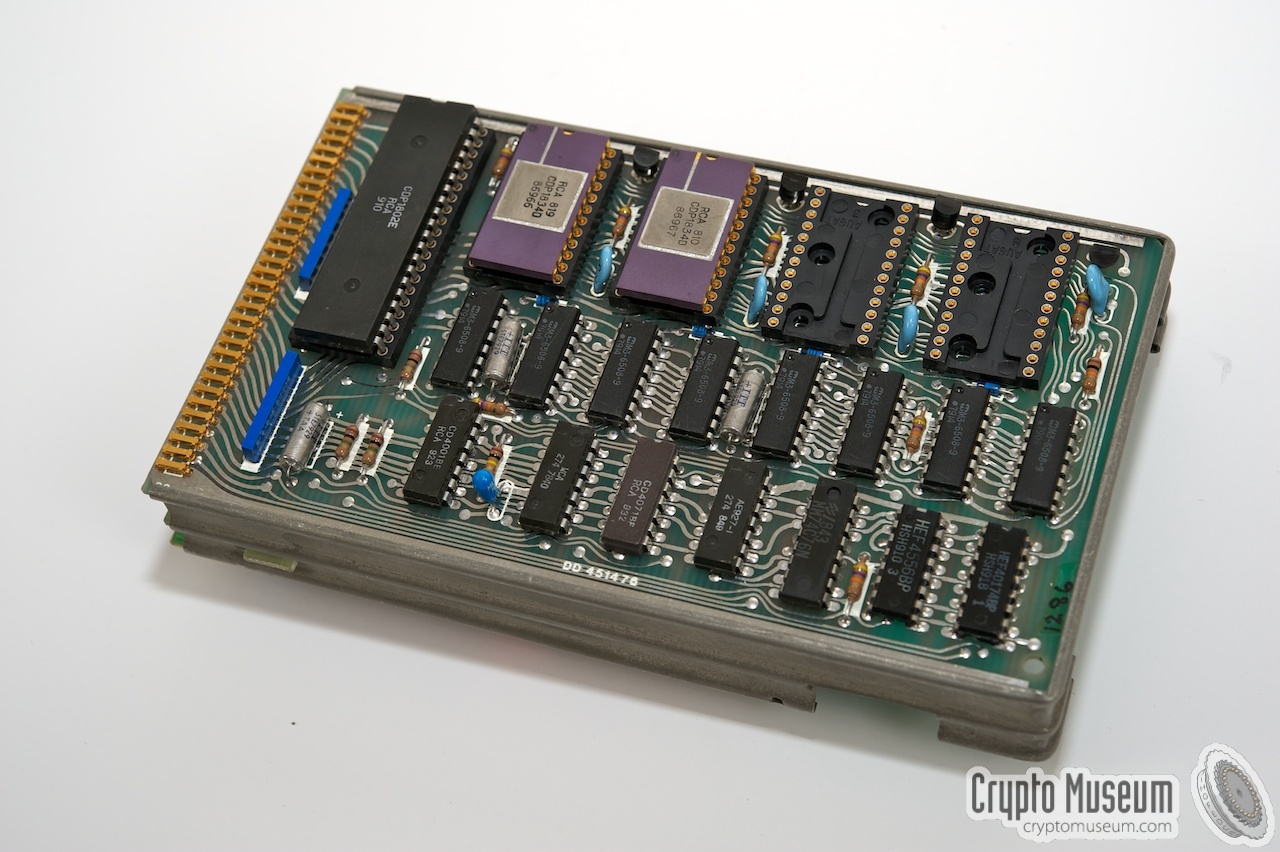
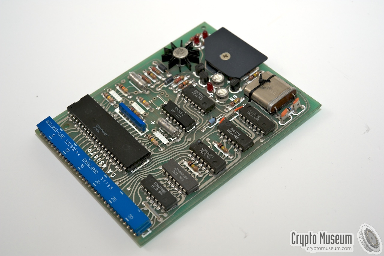
It consists of a metal frame, holding three PCBs:
the Processor Board,
the Audio Board
and the Interface Board.
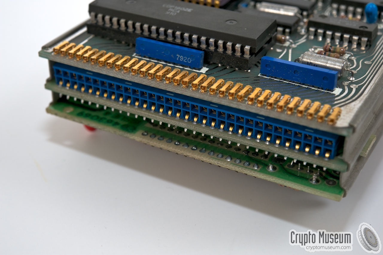
The latter is in between the two other boards
and can easily be pulled out. Setting of the
serial baud rate and word format is described above.
The boards are connected together at one end by means of a
backplane. This backplane is part of a
flex PCB that is also connected to the keyboard PCB
(mounted in the top half of the case). The keyboard also holds the display.
|
|
|
According to date codes on the various components, the MA-4231 shown here
was manfuctured in 1979 or 1980.
The unit is powered by a 6V rechargeable battery
that is mounted in the bottom half of the case. Although the battery in the
image looks brand new, it should be considered lost after so many years.
More about the batteries and power supply above.
|
|
|
|
Any links shown in red are currently unavailable.
If you like the information on this website, why not make a donation?
© Crypto Museum. Created: Thursday 26 August 2010. Last changed: Thursday, 14 December 2023 - 10:19 CET.
|
 |

|
|
|
| |