|
|
|
|
|

|
|
UK Norway Spy radio RX
Clandestine radio receiver
Type 31/1 — also known as Sweetheart —
was a miniature valve-based clandestine receiver,
developed in 1943 by the Norwegian Willy Simonsen, for use by the British
Special Operations Executive (SOE)
during WWII.
Approx. 50,000 units were manufactured by Hale Electric Co. Ltd in London (UK),
that were dropped over occupied Europe, in particular in France and Norway [2].
|
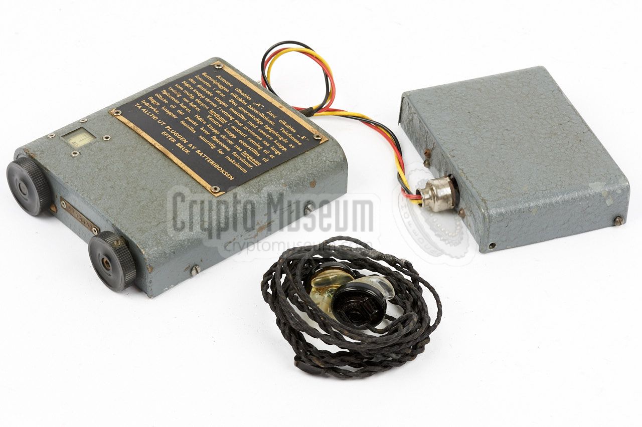
The device consists of a small body wearable unit — the actual receiver
— a separate battery pack,
and a special pair of earphones that came in a hermetically sealed
tobacco tin, as it could not withstand the low pressure in an airplane.
The receiver is small enough to be transported unobtrusively in the pocket
of, say, a coat, and is powered by two batteries that supply 4.5 V (LT)
and 30 V (HT) respectively. Due to the use of crystal earphones 1
it uses very little power.
The HT battery lasted for up to 200 hours,
whilst the LT battery had to be swapped every 50 hours.
|
|
|
|
The receiver does not have a power switch, and can only be switched off
by disconnecting the battery pack.
Production of the receiver started at the Hale Electric Co. Ltd factory
in London (UK) in 1943, and by the end of the war, approx. 50,000 units
had been manufactured. About 5000 of these were dropped over occupied
Norwegian territory.
It allowed the resistance to listen to the coded messages, broadcast
by the BBC in London. For this reason, Sweetheart is also known
as the Propaganda Set.
The operating instructions are
printed on the body
in English or Norwegian.
|
-
Also because the valve-stages are resistance-capacitance coupled
(rather than by means of transformers).
|
The diagram below provides a quick overview of the controls and connections
on the body of the Sweetheart receiver, when looking at the device from the
rear. The red/black/yellow wiring is fixed to the body of the receiver,
and ends in a 3-pin plug that mates with the 3-pin socket on the
battery box.
The antenna and ground wires should be connected to the
'A' and 'E' sockets.
At the left of the rear panel
is a socket with slide-contacts, that accepts
a Brush hearing-aid earphones plug.
The same plug
is used to fit the twisted cable
to the earbuds. The receiver is turned ON by connecting it to the
battery box.
The tuning controls are at the front panel.
|
|
In 1942, the Norwegian graduate electronics engineer Willy Simonsen
escaped to England where he was put to work at the Inter Services
Research Bureau (ISRB).
He used his knownledge and experience with Norwegian resistance
work, to design a small pocket-size receiver with very low power consumption,
that could be driven for a long time from standard domestic batteries.
|
For the design of the Sweetheart, he was not allowed to use military-grade
components. As a result, the receiver had to be built from standard
domestical – unpreferential – electronic parts.
Furthermore, the receiver could not be built by the highly skilled
craftsmen that assembled the other spy radio sets,
so they had to revert to a regular civil manufacturer.
As it was built under supervision of the SOE,
the receiver was given the designation Type 31/1.
It was nicknamed Sweetheart, probably because of a nice young lady who worked on the
project with Simonsen.
|
|
|
|
Approximately 50,000 Sweetheart receivers were built
by Hale Electric Co. Ltd., at a price of just 8 GBP each.
About 5000 of them were intended for the Norwegian
government in exile, and were subsequently dropped over occupied
Norwegian territory where they were used by the resistance.
|
The image on the right shows three young men, sitting in a hole
in a forest near Hvarnes, using the Sweetheart receiver.
The image was taken in the summer of 1944.
From left to right: Josef Haraldsen (district leader),
Erling Slorvik (radio telegrapher) and Hans Lien (chief arms officer).
Together they formed the leaders of the secret organisation
MILORG D-15 (Vestfold).
Hidden safely in the wide forest near Hvarneskollen, south-east of Oslo,
they exchanged hundreds of messages with London [3]. More images of the
D-15 Vestfold group below (copyright unknown).
|
|
|
|
MILORG — short for: Military Organisation — was the organised Norwegian
Resistance that served directly under the Norwegian Armed Forces High
Command (FOR), which resided during the war at Kingston House in London —
the same address as where King Haakon VII and the Norwegian Government in exile
were located [4].
During WWII, MILORG executed a range of resistance and sabotage
activities.
By spring 1945, MILORG had about 40,000 men under arms in Norway.
|
The receiver was powered by two batteries that were installed in
the battery box shown in the image on the right. A standard 4.5V
torch light battery was used for the LT voltage. It had to be
replaced after 50 hours of use.
The HT voltage was provided by a 30V hearing-aid battery, and lasted
for up to 200 hours. The battery box has a three-pin socket that
mates with the power plug of the receiver.
|
|
|
To keep the power consumption of the receiver as low as possible,
crystal earphones were used in stead of regular headphones. As these were not
readily available in the UK, they had to be imported from the USA,
where they were made by Brush for use in early electronic hearing aids.
The image on the right shows an original Brush earpiece, in which the
crystal element is made of Rochelle salt.
As these elements could not withstand the low pressure in an airplane,
they were supplied in a hermetically sealed tobacco tin.
A warning on the box informs the user about this.
|
|
|
A 10-metre long wire was supplied with the kit, for use as antenna.
It has a black plug at one end — that should be inserted into the
socket marked 'A' — and a crocodile clip at the other end, which
can be used to affix it somewhere.
A 3-metre ground wire was supplied as well. One end of this cable
should be inserted into the socket marked 'E', whilst the other end
should be connected to ground (e.g. a metal water pipe or the central
heating system).
|
|
|
|
The Type 31/1 – Sweetheart – receiver is extremely small for its time, and was designed
for low power consumption. It was powered by two
batteries: one standard 4.5 Volt torch battery for the filaments
and a small 30 Volt HT battery, commonly used in hearing aids, for the
anode voltage.
|
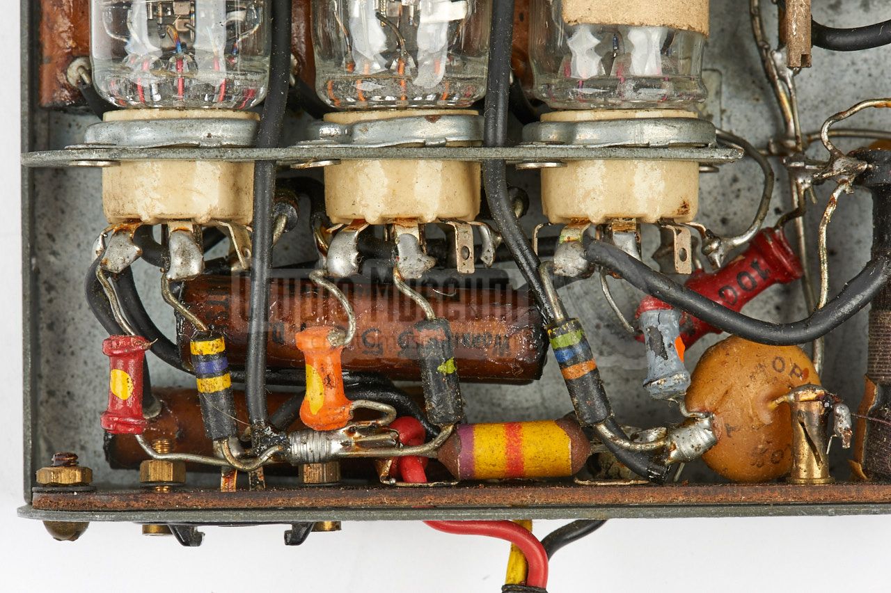
The interior of the receiver can be accessed by removing four screws (two
at either side) and taking off the case shell.
The image on the right shows the interior after removing the case shell.
The circuit is built around 3 identical directly-heated low-power miniature 1T4
valves (tubes) that – like the crystal earphones – were imported from the USA.
The valves are installed in ceramic sockets,
that are mounted in a vertical subframe,
with the passive parts (resistors and capacitors) –
fitted in the narrow space
between the frame and the rear of the case – soldered to their contacts.
|
|
|
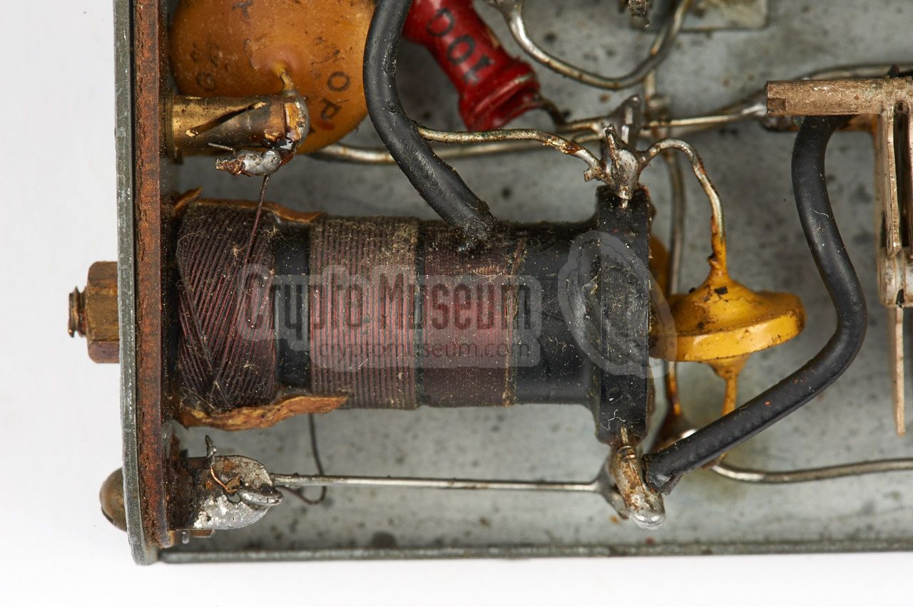
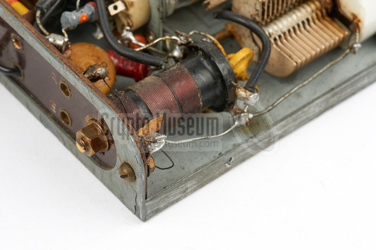
The 3-piece antenna coil
is mounted to the rear panel, and is connected
to the two variable capacitors that are operated by the two knobs at the
front panel. The circuit is dimensioned in such a way, that it still
works when the HT voltage has dropped to 20V. As a result, the 30V HT battery
lasted between 150 and 200 hours. The LT battery had to be swapped every
50 hours.
The receiver covers a frequency range from 6 to 12 MHz in a single band,
with its dial calibrated in metres. This made the receiver ideal for the
reception of spoken coded messages, broadcast by the BBC in London, but less
so for narrowband CW transmissions on the Short Wave (SW) bands.
|
Below is the circuit diagram of the receiver, as it is found on the
instruction sheet, and sometimes inside the case shell as well.
The circuit is built around three identical directly-heated low-voltage
1T4 valves (tubes) and consists of a regenerative
detector (V1) followed by two AF stages (V2 V3).
The final stage (V3) delivers its output to a pair of high-impedance
crystal earphones, that are connected to socket (P). The two supply voltages
(4.5V LT and 30V HT) are connected at the right. Note that the (-) pole
of the 30V battery and the (+) pole of the 4.5V battery are both connected
to ground. This is done to provide a slightly negative voltage to the
g1 of each of the valves.
|
|
The following sound sample of the BBC News broadcast on 12.095 MHz (25 m),
was recorded by Karsten Hansky in Germany on 16 August 2018 at 20:00 hours,
using the Sweetheart receiver in his collection. It demonstrates the excellent
quality of the receiver, even after all these years [7].
|
|
People who are restoring an old Sweetheart receiver, or who want
to build a replica, might be interested in any or all of the following
files:
|
Device Spy radio receiver Purpose Clandestine reception of BBC and other stations Developer Willy Simonsen Manufacturer Hale Electric Co. Ltd. (Londonw, UK) Model Type 31/1 Codename Sweetheart Country UK Year 1943 Users SOE, Resistance Frequency 6 - 12 MHz (dial calibrated in metres) Valves 3 × 1T4 Output High impedance Earphones Brush hearing aid crystal earphones Antenna 10 m insulated wire Counterpoise 3 m wire Power 4.5 V (LT) and 30 V (HT) Current 50 mA (LT) and 0.5 mA (HT) Dimensions 140 × 110 × 30 mm (battery 100 × 80 × 25 mm) Weight 500 g (battery box 400 g) Quantity ~ 50,000
|
|
|
|
Any links shown in red are currently unavailable.
If you like the information on this website, why not make a donation?
© Crypto Museum. Created: Monday 21 September 2009. Last changed: Wednesday, 05 November 2025 - 12:13 CET.
|
 |

|
|
|


