|
|
|
|
|

|
|
USA Motorola LPC SAVILLE STU-III → STU-II →
Secure voice and data gateway · Remote
STU-III/R is a 3rd generation secure voice and
data terminal with remote control interface (RCI),
developed around 1991 by Motorola
in Seguin (Texas, USA). The device is
compatible with STU-III and STU-II (KY-71)
terminals and uses a KSD-64A as the
Crypto Ignition Key (CIK).
When used in STU-II compatible mode, a KEY can be loaded by means of a
KOI-18 or KYK-13 key loader.
|
The device is similar in function to STU-III phone equipment
and to the Motorola SECTEL family of secure phones,
but its purpose is different. The STU-III/R
has no handset or display and is not intended for direct operation by a user.
Instead, it should be controlled by an External Remote Controller (ERC),
which in most cases will be a secured PBX (exchange), called a RED SWITCH.
The STU-III/R will usually be mounted in a rack.
The PBX communicates with it, via a serial RS232 interface, whilst audio
signals (transmit and receive) are analogue (600 Ω terminated).
|
|
|
When mounted in a 19" rack, two STU-III/R units can be mounted side-by-side.
Speech from the secured PBX is digitised by means of an LPC-10 vocoder.
It uses very little bandwidth, allowing it to be used over a standard analogue
PSTN line, at the cost of reduced illegibility. The data is then encrypted
by means of an NSA Type 1 algorithm.
In STU-II compatible mode, this is SAVILLE.
Likewise, the encrypted LPC-10 data from the telephone line is first
decrypted using the same NSA
Type 1 algorithm, and then used to
reconstruct (sythesize) the original speech again. The device has strict
RED/BLACK separation, which is necessary to avoid RED (unencrypted) data
from leaking to the BLACK (insecure) network.
The price of a STU-III/R in 2005 was US$ 8227 [2].
|
MISSING —
Crypto Museum has two STU-III/R units in its collection, but from both
devices the crypto unit (key generator) is missing.
These have probably been removed as part of
the declassification procedure. For this reason, we are not able to bring the
devices back to working condition. We are still looking for two suitable
crypto boards for the restoration of these devices, so that they can be
demonstrated again.
➤ Contact us
The image below shows the front panel of the STU-III/R. It holds all controls
plus a receptacle for the Crypto Ignition Key (CIK) and a socket for connection
of a DS-102 fill device,
such as the KYK-13 or the KOI-18. The latter is only
needed when the STU-III/R is used in STU-II (KY-71) compatible mode.
The unit is powered by an external Power Supply Unit (PSU) that is connected
at the rear. Power is enabled with the Power switch at the front panel.
When the unit is in operation, the internal KEY memory is retained by a
backup battery
that can be accessed from the front panel. It is installed
behind a removable cap.
KEY memory can be purged (ZEROIZED) at all times.
At the bottom right is a receptacle for the
KSD-64 key storage device. This is also known as a KEYCEPTACLE.
In STU-III compatible mode, the KSD-64 should be supplied
with a valid Seed KEY (by registered courier).
With the Seed KEY, the user can dial into a secret 800-number at NSA
to have it converted into an Operational KEY. The Operational KEY is then
split into two parts, one of which is stored inside the STU-III/R. The other
part is stored on the KSD-64
which will then become the Crypto Ignition Key (CIK).
From then on, the STU-III/R and the CIK are 'paired'.
All connections to external devices are at the rear (with the exception of
the KEY FILL device, which should be connected at the front). At the bottom
centre is a 9-pin DE-9/M receptacle marked J1 for connecting the
external PSU. To its left is an RJ14 socket marked J6
for connection to the analogue PSTN line. At the top centre is a
DB-25/S receptacle J4
with the Remote Control Interface (RCI). It carries
digital control lines (RS-423A) and in/out analogue audio lines (600Ω) for
connection to a secured local exchange (PBX).
The Red Digital receptacle (J3) should also be connected to the
PBX, if it can process digital in/out data directly to/from
the LPC-10e vocoder.
|
- High quality voice, and high-speed data at 9600 baud (MRELP)
- 4800 baud voice communication according to government standard CELP 3.1
- Interoperable with STU-III
- Interoperable with STU-II (KY-71) in Net Broadcast Mode
- External modem connection (black)
- Black digital alerting capability
- Emergency ZEROIZE at front panel
- Clear/secure or secure-only operation
- Configurable 2/4-wire PSTN interface
- Red digital voice output for digital conferencing
- VOX or push-to-talk half-duplex operation
- Simple user interface for FILL operations
- Ruggedized enclosure for industrial and airborne environments
- Wide range PSU (90-250V AC, 50-440 Hz)
- AUTOVON and IVSN peemption tone detection (4th column DTMF)
|
The diagrams below show the various configurations in which the STU-III/R
could be used. In the simplest setup, only a handset with integrated
Push-To-Talk (PTT) button could be connected directly to the Remote Control
Interface (RCI). It allows secure conversations to be answered in half-duplex
and full-duplex mode. It is also possible to use a modified telephone set
for this.
In the default configuration however, the STU-III/R would be placed between
an analogue subscriber line (POTS, PSTN) and the local analogue
PBX inside a building. In this case, the PBX has analogue voice
circuits, whilst it controls the STU-III/R via a digital serial RS423 port
(RCI).
If the PBX has digital voice circuits, it could be connected directly
to the red digital port of the STU-III/R. This would generally provide
a better audio quality. In addition to the red digital port, the PBX
would also be connected to the RCI port, to control the STU-III
via its serial RS423 port.
This configuration was also used for a secure teleconferencing setup.
In all of the above configurations, the analogue interface is used at
the black side, as it is connected to an analogue PSTN (TELCO).
The black signals are also available in digital form however, which
can be useful when connecting the STU-III/R to an external MODEM.
In the above example, the STU-III/R is connected to an external
modem, which in turn is connected to a RF transceiver (TRX).
In most cases, RF links were used in half-duplex mode, which
means that the user had to press a PTT button — integrated in
the handset — when speaking, or that the PBX needed to have
a VOX circuit.
|
In STU-III mode, keys are generated externally by a COMSEC authority,
and are transferred to the device on a
KSD-64 Key Storage Device.
Once the keys are loaded, the KSD-64 is converted
into a Crypto Ignition Key (CIK) which is paired with the device.
The CIK has to be installed to enable secure communication.
Without the paired CIK, the STU-III/R cannot be used in secure mode.
➤ More about the KSD-64
|
|
|
In STU-II mode, keys are transferred to the device by means of a
DS-102
key transfer device like the KYK-13 or the KOI-18.
The image on the right shows the KYK-13 connected to
the FILL port of the STU-III/R. The user must press the grey FILL
button on the front panel of the STU-III/R to initiate a transfer.
In this mode, the KSD-64 is used as the CIK. The CIK is
always paired with the devide and must be installed to enable
secure operation.
➤ More about key loaders
|
|
|
When security is compromised, the keys inside the STU-III/R have
to be purged immediately. By convention this is always a two-step
or double-action procedure, such as pressing two buttons
simultaneously.
On the STU-III/R it involves pulling-out the
ZEROIZE switch and placing it in the upper position.
To resume normal operation and allow new keys to be loaded into
the device, the switch has to be returned to the lower position first.
|
|
|
The diagram below shows how the STU-III/R was integrated in the existing
infrastructure. The device consists of three compartments: a black side
– connected to the outside world – a red side – connected to the equipment that
must be secured – and a compartment that controls the data streams, the
vocoder, the key generator and the encryption. A plastic KSD-64A key
can be used as a fILL device and also as a Crypto Ignition Key (CIK). In
STU-II compatible mode, an external FILL device (KOI-18
or KYK-13) is used
to load the keys, whilst the KSD-64A is used as the CIK.
After initialisation, the CIK is paired with the STU-III/R and must be
installed for operation.
The device has an internal modem at the black side, which forms the interface
between the digital lines to and from the device and an analogue 2-wire or
4-wire PSTN telephone line (J6).
The black side is also available in digital
form, so that it can be connected to an external modem (J5).
The latter is typically used to connect an HF modem which in turn is
connected to a radio transceiver.
At the red side, the signals are also available in analogue and digitial form,
so that the External Remote Controller (ERC) — typically a secured
telephone switch (PBX) — can either use the analogue audio lines
(J4)
or the digital data directly from the LPC vocoder (J3).
The ERC can send commands (e.g. dial codes) to the STU-III/R via a serial
RS232 that is line embedded in J4.
|
The actual STU-III/R unit measures 324 × 267 × 81 mm and weights
5.7 kg. All controls are at the front,
whilst the connections to the outside world are
at the rear. When placed in a 19" rack,
two units can be mounted side-by-side.
Although the device is intended for use in combination with a
PBX, it is possible to wire a telephone unit or handset
directly to the RCI connector (J4) for stand-alone use.
|
|
|
The STU-III/R does not have an internal mains power supply unit (PSU).
Instead, it must be powered by the approved external wide-range PSU
shown in the image on the right.
The primary side must be connected to the mains 90-265V AC.
The secondary side provides necessary +5V, +12V and -12V DC voltages
that should be connected to a 9-pin DE9/S receptable (J1)
at the rear of the STU-III/R.
➤ Pinout of the 9-pin connector
|
|
|
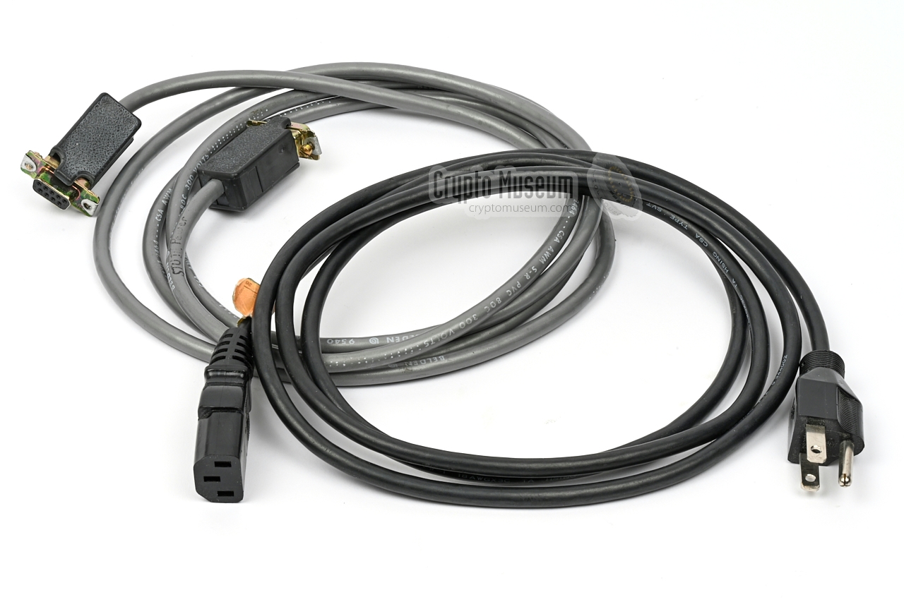
The STU-III/R was supplied with two power cables: (1) for connection
to the AC mains and (2) for connection to the
power socket (J1) at the rear of the device.
The latter is a 1:1 cable with a DE9/S connector at one end
and a DE9/P at the other end. The cable must be shielded.
The mains cable shown here, is for connection to the AC mains
network in Northern America. For other parts of the world, such
as continental Europe, a different cable should be used.
|
|
|
|
|
Crypto Ignition Key
KSD-64
|
|
|
To secure the key material inside the STU-III/R, all keys
are stored in encrypted form, using an internally generated random key
which is stored on a removable KSD-64 Key Storage Device (KSD)
that is used as a Crypto Ignition Key (CIK).
Once the STU-III/R is initialised and valid keys are loaded into its
key compartments, the CIK is paired with the device. Without the CIK, the
device is useless. Furthermore, the CIK cannot be used to activate another
STU-III/R device with which it is not paired.
➤ More information
|
|
|
When using the STU-III/R in STU-II compatible mode, a valid
NET KEY must be loaded into the device by means of a key transfer device
that supports 128-bit key material in DS-102 format,
such as the KYK-13 shown on the right.
The device has a male and a female connector that are connected in parallel.
It can be connected directly to the U-229 socket at the front panel,
or via an optional fill cable.
➤ More information
|
|
|
As an alternative to the KYK-13 it is possible to use the
KOI-18 shown in the image on the right. It transfers the
NET KEY from punched paper tape directly to the STU-III/R.
The device only has a male U-229 connector, and must therefore always be
connected to the STU-III/R via the fill cable shown below.
➤ More information
|
|
|
To connect the KOI-18 key transfer device to the STU-III/R,
a special FILL cable must be used, such as the one shown in the image on
the right. It can also be used between the KYK-13
and the STU-III/R.
The FILL cable consists of a 5-wire cable with a female U-229 connector
at either end, wired 1:1. The cable is also used for transferring keys
from a KOI-18 to a KYK-13 key filler.
|
|
|
Each STU-III/R was supplied with an A5-size ring-bound booklet
with instructions on how to setup, use and maintain the device.
The booklet contains full pinouts of the various connectors
and provides some hints on the commands that can be used via the
RCI port (J4).
➤ Read the manual
|
|
|
|
The STU-III/R is housed in a ruggedised black die-cast aluminium enclosure,
which consists of a compartmented frame with removable top and bottom lids.
The identical top and bottom panels are held in place by 7 black screws
each, plus two long screws that extend from top to bottom. At the bottom, these two screws are sealed to provide evidence that the case has been opened.
|
The bottom section, shown in the image on the right, is completely shielded off
from the rest of the device. The main compartment contains one large PCB
of which the solder side is visible here.
This board contains the TELCO interface, which connects the device to an
analogue PSTN line. It also holds
the LPC-10 vocoder.
The board is connected to the PCBs at the top side, via a shielded DB25
connector in one of the corners.
In the other corner is a small compartment that contains the receptacle for
the KSD-64 CIK. At the center of the front is the red on/off switch.
|
|
|
|
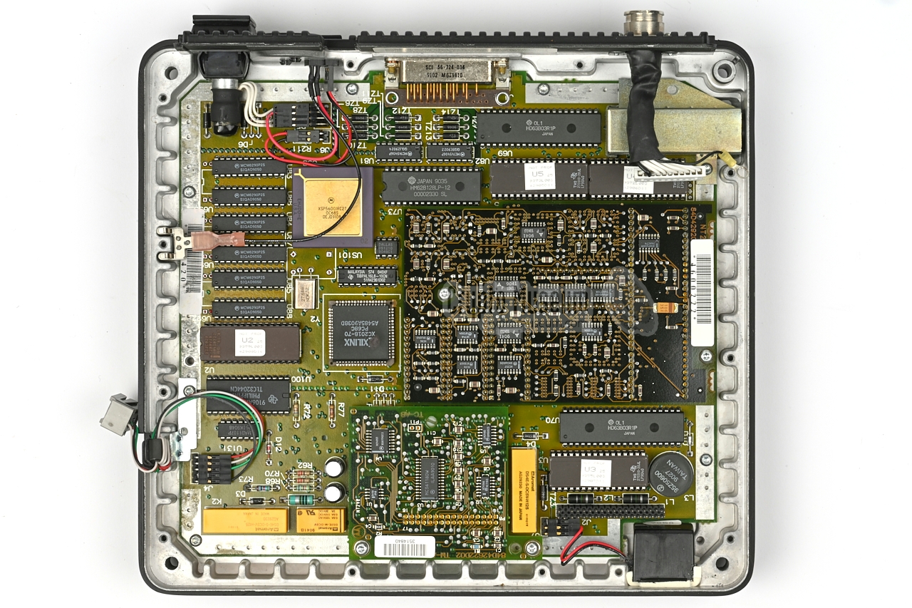
All other electronic circuits are at the top side of the device, shown in
the image below. There are two large PCBs of which the upper one
is visible here. It holds a microprocessor with RAM and firmware
in EPROM — responsible for handling the RCI —
plus the RED analogue audio interface.
|
The RED analogue signals and the digital RCI interface (RS232) are
available on the DB25/S connector (J4) at the rear centre
of the board. It is intended for connection to the local PBX.
The far side of this board also holds part of the BLACK digital interface,
which is available on a DB25/P connector (J5) at the rear.
It is physically separated from the RED and RCI interfaces to avoid
side channel leakage.
The upper board is connected to the other PCB — mounted below it — and to
the rest of the device via several flatcables and flying leads at
the edges of the PCB.
|
|
|
|
Note the tamper switch,
which is located just behind the front panel,
towards the centre. The switch is engaged as soon as the top panel is
removed, and ensures that all cryptographic material held inside the
device's CMOS RAM is purged. It has the same effect as ZEROIZING.
|
The upper board is held in place by 10 black screws around the edges
plus the 4 retaining screws of the RCI and BLACK digital connectors.
After removing these screws and disconnecting the various cables around
the edges, the upper board can be removed as shown on the right.
The lower board is slightly smaller than the upper one. It holds the RED
digital interface and the encryption unit. Towards the front of the PCB
is a large 64 pin socket
into which normally the key generator is installed.
Unfortunately this unit has been removed from the device shown here.
|
|
|
This means that this particular device cannot be used or demonstrated anymore.
The missing key generator is a small daughter card that is similar (but not
identical) to the key generator of the
Motorola STU-III shown
here.
The card should be fitted in the large 64-pin socket on the lower board
and is held in place by two screws: one at the centre and one next to the connector.
Note that the lower board is almost identical
to the lower board inside the
Motorola SECTEL 2500 (STU-III) desktop telephone set,
which suggests that the products were developed more or less simultaneously. 1
In the STU-III/R, the board is rotated by 90° compared to the
SECTEL STU-III.
|
-
It is likely that the STU-III/R hardware is a spin-off from the
STU-III hardware development.
|
When we received our two STU-III/R units in January 2023 [1], they were
in the state visible in the images. That means that no restoration or cleaning
was required for the time being. However, when inspecting the
interior, we discovered that the crypto hearts (i.e. the key generators)
were removed from both units, probably as part of the declassification
procedure. This means that we are unable to test and demonstrate the
units, until we find two STU-III/R key generators. 😢
|
|
At the rear of the device are 4 sockets for connection to the
outside world, marked J1 and J3 - J5. Another connector is at the
front panel, and is used for connection of a key fill device
when the device is used in STU-II compatible mode.
The wiring of the connectors is specified below.
|
SSB Internal control bus for diagnostic monitoring +5V +5V, 2.5A - +5V Sense
+5V Sense Return (ground) -12V -12V, 300 mA +5V +5V return GND Ground +12V +12V 400 mA ±12V +12V return
|
|
|
This connector carries the digital output from the internal LPC-10e
vocoder, which may be passed to a PBX capable of handling digital
voice data from an RS232 port. The connector also carries a digital
input, so that the PBX can send its digital data straight to the
STU-III/R without converting it to the analogue domain first.
|
AA Protective Ground (GND) BA Transmitted Data (TXD) BB Received Data (RXD) CA Request to Send (RTS) CB Clear to Send (CTS) CC Data Set Ready (DSR) AB Signal Ground (GND) CF Data Carrier Detect (DTD) DB Transmitter Signal Element Timing DD Receiver Signal Element Timing CD Data Terminal Ready
|
|
|
|
Remote Control Interface (RCI)
J4
|
|
|
|
The Remote Control Interface (RCI) allows the device to be controlled remotely.
This connector is typically wired to an external secured PBX which can use
the STU-III/R to encrypt and decrypt calls to and from the outside world.
The connector carries a serial port through which the PBX can dial out,
similar to operating the keypad on a telephone set. It also holds the analogue
voice in/out lines and a couple of control signals.
|
AA Protective Ground (GND) BA Transmitted Data (TXD) BB Received Data (RXD) CA Request to Send (RTS) CB Clear to Send (CTS) CC Data Set Ready (DSR) AB Signal Ground (GND) CF Data Carrier Detect (DTD) PTT Push-to-Talk LPCIN LPC Input Enable TXPAUD Transmit Audio RXAUD Receive Audio CD Data Terminal Ready (DTR) RXAUDRET Receive Audio Return TXAUDRET Transmit Audio Return
|
|
|
This connector holds the digital in/out signals of the BLACK side.
It bypasses the internal modem and can be used to connect an
external one, such as a HF modem for communication via radio.
|
AA Protective Ground (GND) BA Transmitted Data (TXD) BB Received Data (RXD) CA Request to Send (RTS) CB Clear to Send (CTS) CC Data Set Ready (DSR) AB Signal Ground (GND) CF Data Carrier Detect (DTD) DB Transmitter Signal Element Timing DD Receiver Signal Element Timing CD Data Terminal Ready
|
|
|
At the rear of the device is a 6-pin
RJ-25 (6P6C) modular socket
for connection to a 2-wire or 4-wire subscriber line.
When connecting to a 2-wire line, an RJ-11 connector can be used,
as only the middle two contacts (3 and 4) are needed.
The pinout is as follows:
|
|
When connecting to a 4-wire line, the pinout is as follows:
|
T1 TX analogue to provider (A) R1 RX analogue from provider (A) R2 RX analogue from provider (B) T2 TX analogue to provider (B)
|
|
|
The TELCO socket (J6) can also be wired to an 8-position
RJ-45 (8P8C)
interface by using an optional adapter. In this situation all 6
contacts of the RJ25 socket are used. Note that the extra pins
(1,2, 5 and 6) can only be used when RJ45 and MI/MIC are enabled in ERC.
|
- Resistor to pin (6) to adjust the output level 1
- MI/MIC (off-hook detection) 2
- TIP
- RING
- MI/MIC 2
- Resistor to pin (2) 1
|
|
-
Adjust output level between 0 and -12dBm into 600Ω.
This option requires RJ-45 to be enable in ERC.
-
Pins 2 and 5 are shorted when the handset is off-hook.
This option requires MI/MIC to be enabled in ERC.
|
GND Ground - unused ACK FILL request acknowlegment DATA Serial fill data into STU-III/R CLK Serial clock into STU-III/R
|
|
Device Secure voice and data gateway Purpose PBX encryption/decryption, secure conferencing Manufacturer Motorola Country USA Users US Government, NATO Encryption NSA Type 1, SAVILLE Modes STU-III, STU-II CIK KSD-64 FILL DS-102 Backup 3V 1/3N Lithium (at front panel) - 2 years Approval USA, Belgium, Germany, UK Temperature -20°V to +70°C Storage -55°C to +85°C Humidity 95% non-condensing Altitude 35,000 feet Dimensions 324 × 267 × 81 mm Weight 5.7 kg Price US$ 8227 in 2005 [2]
|
V.32 4800 and 9600 baud with Echo Cancelling V.26 2400 baud with Echo Cancelling Input +6 to -43 dBm Output 0 to -12 dBm (adjustable)
|
Async 70, 110, 300, 500, 1200, 2400, 4800, 9600 baud Sync 2400, 4800, 9600 baud Data RS232C compatible
|
- 2400 baud, interoperable FED-STD-1015
- 4800 baud, interoperable FED-STD-1016
- 9600 baud, Motorola proprietary
|
Black Analogue: PSTN 2- or 4-wire TELCO or Autovon
Digital data: RS232C Red Analog voice: 4-wire balanced 600 Ω
Digital voice: RS-232C Remote RS-423A
|
Input 90 to 265 C/AC, 50 to 440 Hz Current 305 mA at 117V Fuse GMC 1A/250V Dimensions 165 x 114 (140) 1 x 64 mm Weight 528 grams
|
|
|
|
Any links shown in red are currently unavailable.
If you like the information on this website, why not make a donation?
© Crypto Museum. Created: Wednesday 04 January 2023. Last changed: Saturday, 11 February 2023 - 23:39 CET.
|
 |

|
|
|


