|
|
|
|
|

|
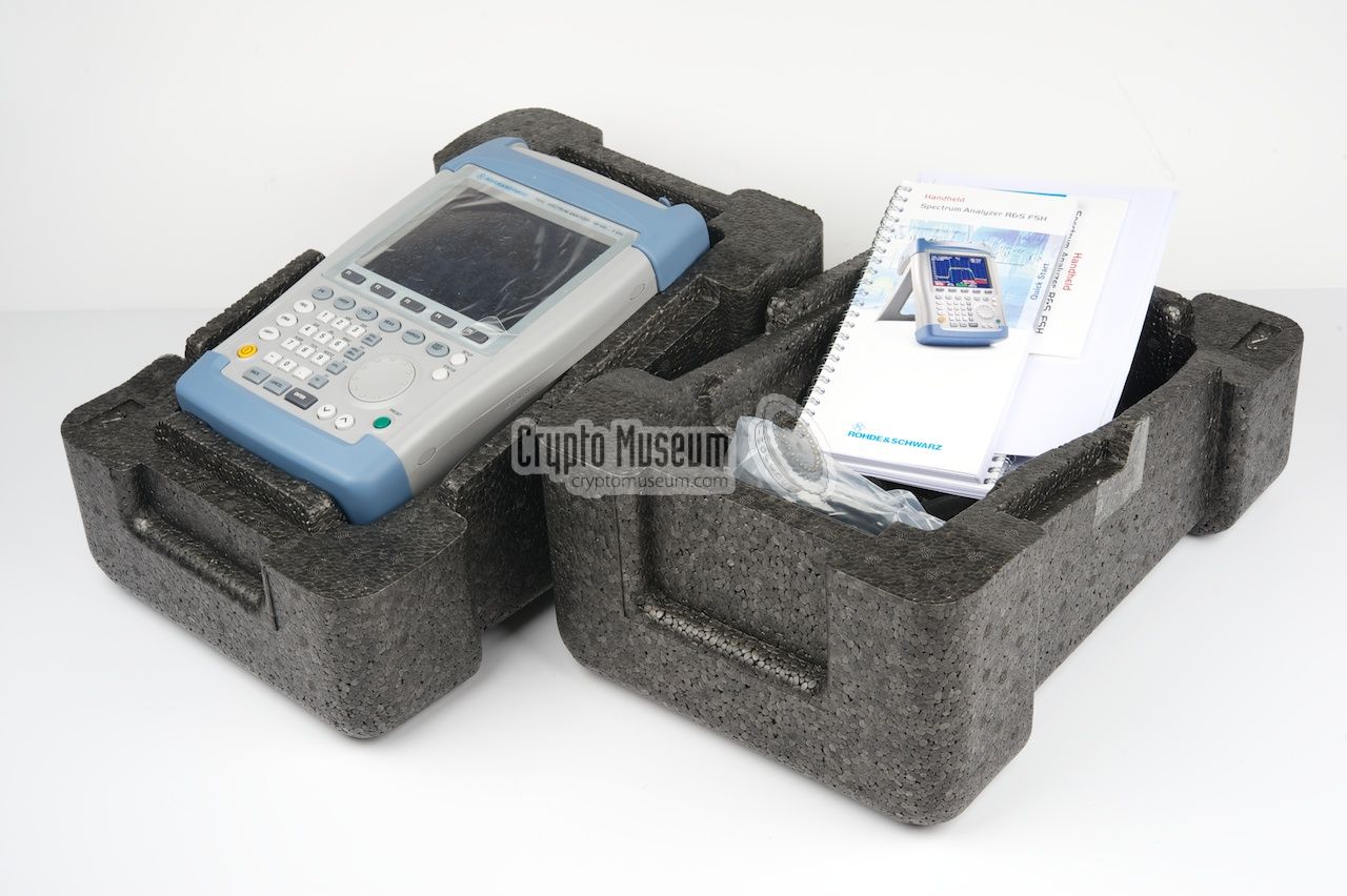
Portable Spectrum Analyzer
The FSH-3 is a small portable fully-featured professional spectrum analyzer,
developed by Rohde & Schwarz
in Germany [1] around 2005. It can be used for fault finding,
field maintenance, e.g. on mobile radio stations,
and monitoring of the radio spectrum.
Furthermore, the FSH-3 can be used for location of (intermittent)
interferences and even for locating
hidden transmitters (bugs).
|
The FSH-3 covers a frequency range from 100 kHz to 3 GHz and has a resolution
bandwith of 100 Hz to 1 MHz. It can be powered by an external mains adapter
or by the built-in rechargable batteries.
With the built-in tracking generator, the FSH-3 can be used to measure
the properties of filter networks and amplifiers.
All controls are at the front panel, directly below the full-colour display.
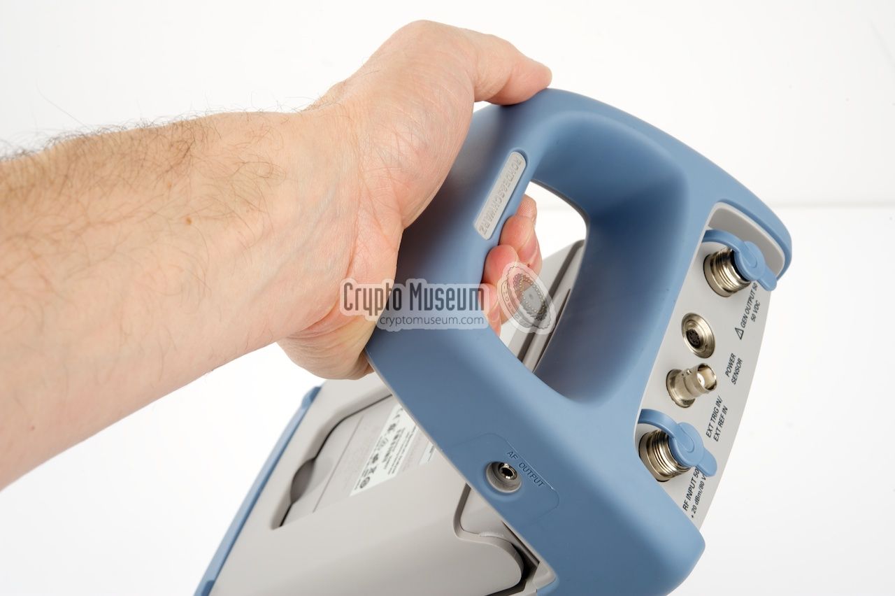
The connectors for RF in, RF out (tracking generator) and optional Power Sensor
are all at the rear, just above the grip. At the left, hidden in the grip
is a 3.5 mm jack socket for connecting a pair of headphones.
|
|
|
Rohde & Schwarz was among the first manufacturers to introduce portable
spectrum analyzers and the FSH-3 belongs to their earliest developments.
Other members of the the family are the FSH-6 (no longer available)
and the FSH-18. The latter has a frequency range of 10 MHz to 18 GHz
and a resolution bandwidth of 100 Hz to 1 MHz.
The FSH-3 and FSH-18 were succeeded by the FSH-range
of spectrum analyzers and related products like the
PR-100 Portable Receiver.
|
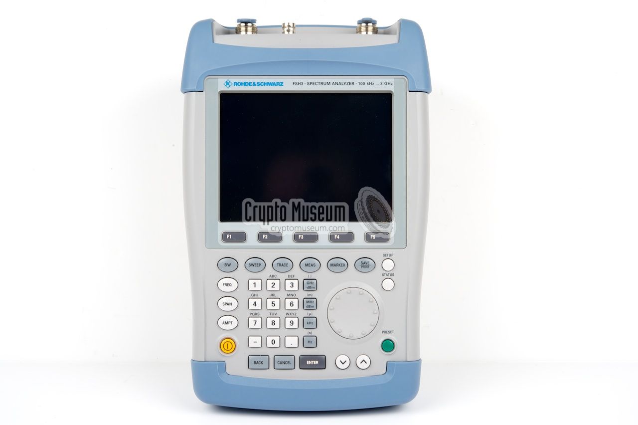
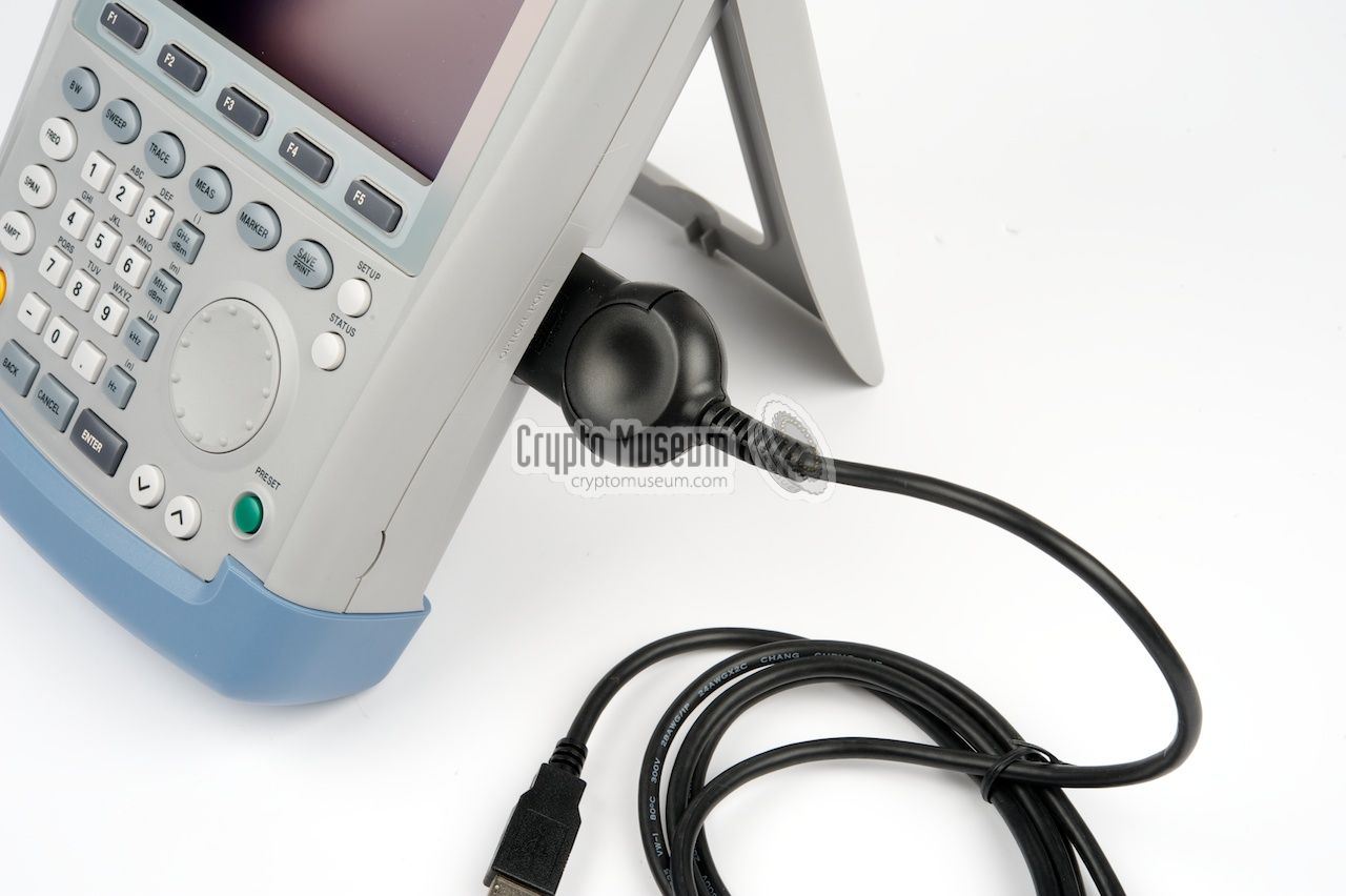
All controls of the FSH-3 are nicely arranged on the clear
uncluttered front panel. The top half of the front panel hold the large
colour LCD screen, with 5 function keys (F1-F5) at the bottom.
The lower half is taken van the keyboard,
which has a row of grey MODE selectors at the top.
The rest of the keyboard consists of a full numerical key pad,
buttons for selecting the required measurement units, and navigation keys.
At the right is a large rotary dial that allows easy adjustement
of parameters. At the bottom left is the (orange) ON/OFF button.
|
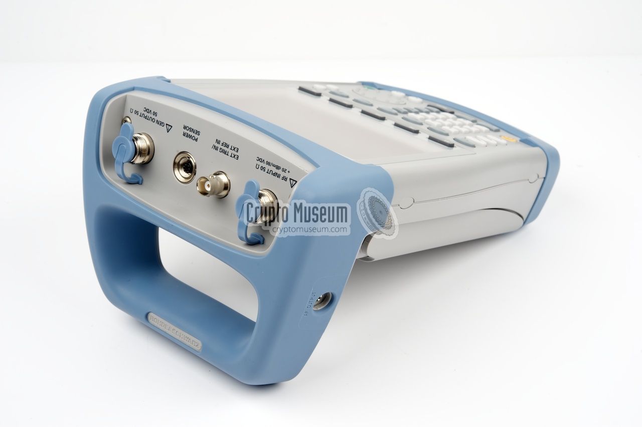
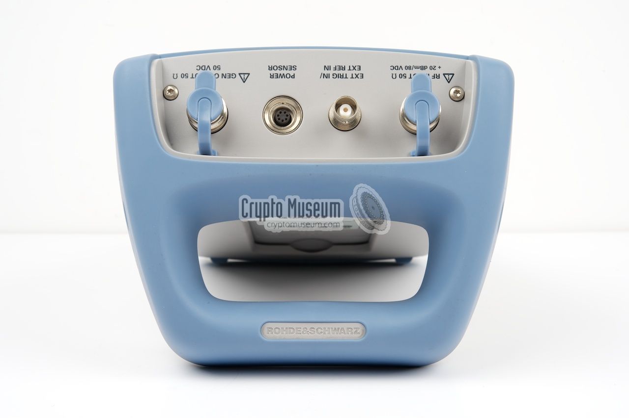
All connections to the FSH-3 are at the rear (just above the display)
and at the sides. All HF connections are at the rear. A signal source
or an antenna is connected to the first connector (at the left, seen
from the front of the unit). The rightmost socket is the output of
the built-in tracking generator. The remaining sockets are for
an external trigger signal and a power sensor.
Two small sockets, one for the mains adapter
and one for a pair of headphones,
are hidden in the lower part of the blue carrying grip.
The headphones can be used to listed directly to the demondulated
signal. Furthermore, an
optical serial port is available at the
right side
of the FSH-3. It can be connected to any PC, by means of
the supplied serial interface or the
USB interface.
|
|
The FSH-3 is a very convenient tool for locating
HF eavesdropping devices,
also known as 'bugs'.
Such bugs are generally very low power transmitters
that operate on a fixed frequency in the VHF, UHF or SHF band. Finding bugs
is commonly known as bug tracing, bug fixing or sweeping.
|
Over the years, a wide variety of tools to perform a sweep have been
developed by manufacturers all over the world. Such tools are often
described as Technical Surveillance and Counter Measures (TSCM)
and the FSH-3 falls into that category.
When searching for an unwanted radio signal, it is important
to investigate only a small portion of the frequency spectrum,
e.g. 100 - 200 MHz. If the frequency span is chosen too wide,
it will not be possible to see any small signals. It is also
important to known which signals (stations)
normally resided in that part of the spectrum.
|
|
|
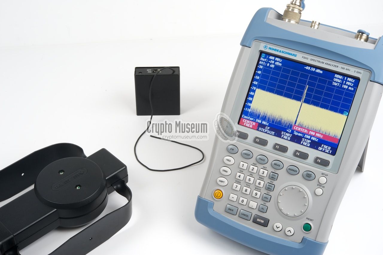
Strong local radio stations will generally appear as a high peak
and can easily mask the weak signals of a radio bug. For example:
when scanning the spectrum between 100 MHz and 300 MHz, the center
frequency should be set to 200 MHz and the frequency span to 200 MHz.
|
The image above shows the FSH-3 with a center frequency of
200 MHz and a span of 200 MHz. This means that the display shows
all signals between 100 and 300 MHz. By using a special directional
antenna, such as the HE-100, the effect of external signals
can be minimised. The image above shows our test-bug at 203 MHz
being detected (at the center) by the FSH-3.
When investigating the signal, it is advised to center the
display at the signal's frequency (203.170 MHz)
and decrease the span to, say, 10 MHz
as is shown in the image on the right.
|
|
|
If the span is further decreased, it should now be possible to
see if the signal carries any modulation. In this case it is an
Frequency Modulated signal (FM), but some bugs have their audio
signal modulated on a so-called subcarrier. These are the so-called silent bugs
or SC-bugs.
|
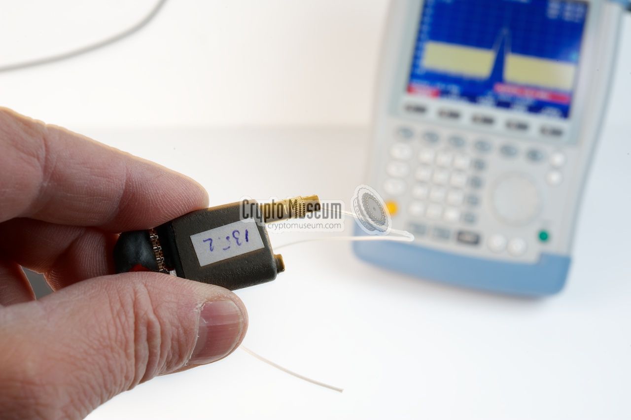
The bug in the example above is just a test bug that is often
used by TSCM personnel to verify the operation of their sweep-equipment.
Real-life professional bugs are often much smaller.
An example of such a professional radio bug is the
ATET S35
shown in the image on the right.
When the option FSH-K3 is installed, the FSH-3 can also be used as
a receiver and can directly demodulate the intercepted signal.
An external headphone can then be used to listen to the signal.
Another R&S device that is very suitable for bug fixing is the
PR-100 digital receiver.
➤ More about radio bugs
➤ Other TSCM tools
|
|
|
The easiest and most reliable way to interface a computer with
the FSH-3 is via an RS232 interface. A suitable cable, that converts
the optical port into a bi-directional serial RS232 port, is supplied
with the device.
The serial port can be used to transfer data from the FSH-3 to the PC
but also to remote control the FSH-3 from the PC.
|
|
|
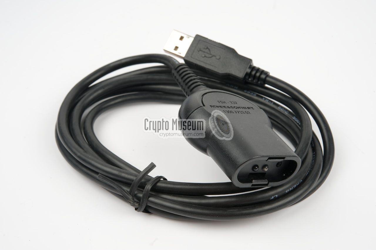
As most modern desktop computers and laptops are no longer supplied with
a serial RS232 port, an suitable USB converter is available as well. It
basically contains a built-in converter from RS232 to USB and makes the
device appear as a COM-port on the PC.
A suitable driver for this interface should be installed on the PC,
and is supplied on the enclosed CD-ROM.
|
|
|
In order to print images (screen dumps) directly from the FSH-3,
an external parallel converter is available. It converts the optical port
into a Centronics-compatible printer port.
A parallel printer can be connected to the 25-way D-type connector on the
interface.
|
|
|
|
A thin light-weight pair of Sennheiser PX-30 headphones is included with
the FSH-3. It should be connected to the Phones socket at the left side
of the carrying grip and can be used to listed to the demodulated
audio of an intercepted RF signal.
|
|
|
The FSH-3 can be powered for approx. 4 hours by the internal rechargable
NiMH batteries, but also by the included mains adapter.
When the FSH-3 is connected
to the mains, the internal batteries are automatically recharged.
The main adapter is suitable for virtually any mains wall socket in
the world. Suitable wall socket pins are included with the adapter
and by we swapped in seconds.
|
|
|
A quick reference manual is supplied with the FSH-3. It is small
enough to be stored with the device and describes the most common
functions of the analyzer.
A more comprehensive Operator's Manual can be found on the supplied
CD-ROM.
|
|
|
|
The FSH-3 comes with a CD-ROM that contains the full Operator's Manual,
as well as the FSH View software that can be run on a Windows PC.
Furthermore it contains information about related products.
|
|
|
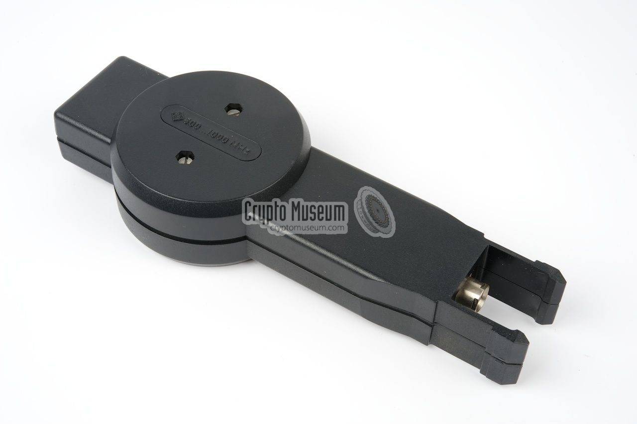
The HE-100 set
consists of three pluggable antenna's and a pre-amplifier
in the shape of a pistol grip, with a field-strength meter at the back.
Depending on the required frequency range,
one of the three antennas is attached to the front of the pre-amplifier,
and is enabled by pressing the trigger-button on the pistol grip.
➤ More information
|
|
|
The HE-100 antenna
was later superseded by the
HE-300 active directional antenna,
which has an extended frequency range from 20 MHz to 7.5 GHz.
At the lower end, the frequency range can be further extended down to 9 kHz
by adding the optional HE-300-HF module.
|
- FSH-B1 - Distance-to-Fault Measurement
- FSH-K1 - Remote Control via RS-232
- FSH-K2 - Vector Transmission and Reflection Measurements
- FSH-K3 - Receiver Mode
- FSH-K4 - 3GPP FDD Code Domain Power BTS/Node Measurement
|
- FSH-Z1 - Power Sensor (10 MHz - 8 GHz)
- FSH-Z2 - VSWR Bridge and Power Divider (10 MHz - 3 GHz)
- FSH-Z3 - VSWR Bridge with DC Bias and Bypass Switch
- FSH-Z14 - Direional Power Sensor (300 mW - 300 W, 25 MHz - 1 GHz)
- FSH-Z18 - Power Sensor (10 MHz - 18 GHz)
- FSH-Z44 - Directional Power Sensor (200 MHz - 4 GHz)
|
- FSH-3
This is the basic model that has a built-in pre-amplifier and covers
a frequency range from 100 kHz to 3 GHz. This is the model that is
featured on this page.
- FSH-18
This model can be regarded the 'big brother' of the FSH-3.
At the upper end, the range has been extended to 18 GHz, but at the
lower end the range is limited to 10 MHz. For frequencies below 10 MHz,
the FSH-3 is required, or any of the later FSH models (below).
- FSH-4/8/13/20
The FSH-range is the successor of the FSH-3 and FSH-18 models. The
range consists of 4 models, each with a different upper frequency limit.
At the lower end of the spectrum, these models can measure as low as 9 kHz.
The upper limits are 3.6, 8, 13.6 and 20 GHz respectively.
|
Another device from Rohde & Schwarz that is even more suitable
for locating covert listening devices (bugs), is the
PR-100.
It covers all frequencies between 9 kHz and 7.5 GHz and directly
demodulates the signal that is visible at the center of the frequency
spectrum display.
In addition, the PR-100
has a waterfall display and many other useful
features. The PR-100 is often used with the
HE-300 directional antenna.
➤ More information
|
|
|
Several years ago, around 2005, Crypto Museum received an FSH-3 as a gift
during a HAM Radio event in Germany.
We used the device for several years to
demonstrate it in combination with the HE-100 directional antenna
for locating
hidden transmitters (bugs).
Although the device we were given had some quirks, it worked
fine until mid-2013, when it suddenly refused to switch on.
After consulting Rohde & Schwarz, it became obvious that our device was
an engineering sample that was not intended for real use. Was that
the end of our FSH-3? No, it wasn't. When the kind people at Rohde & Schwarz
learned that it was for Crypto Museum, they decided to donate us a brand
new one, for which we are most grateful. We are now able to demonstrate
this beautiful and versatile instrument once again and show its wide
range of applications.
We are indebted to Ben Maarleveld and Alfons Verpoorten of
Rohde & Schwarz Benelux [1]. Many thanks!
|
|
|
|
Any links shown in red are currently unavailable.
If you like the information on this website, why not make a donation?
© Crypto Museum. Created: Saturday 21 December 2013. Last changed: Friday, 30 May 2025 - 09:47 CET.
|
 |

|
|
|