|
|
|
|
|

|
Ferrite reception antenna
- under construction
FAP (Russian: ФАП) 1 was a rugged active ferrite antenna
for short wave (SW) reception, developed around 1978 2 in the former
Soviet Union (USSR).
Available as an option to the R-140M radio set (Russian: Р140М),
it was typically mounted at the rooftop of the radio vehicle carrying the R140M.
It is suitable for frequencies from 1.5 to 14 MHz and is operated by
a remote control unit.
The device was used in the USSR and in the
Warsaw Pact countries.
In Poland it was known as FAO. 3
|
The complete FAP system consists of 2 units: the FAP antenna,
housed in a plastic enclosure, and the FAP remote control unit.
The antenna has 3 frequency ranges and can be tuned by means of the coarse
and fine rotary selectors at the front panel, each of which has 15 positions.
Once set, the rotary selectors must be locked in position. 4
The antenna can also be tuned automatically when the control unit is
connected to a suitable receiver control unit (PUR). In the latter case, 10
presets can be setup using
3 pin-configurable matrices
that are hidden behind the hinged lid.
|
|
|
Inside the antenna is a valve-based pre-amplifier that is powered by
the power supply unit (PSU) of the controller, via the
16-wire cable that runs from the controller to the antenna.
This cable also carries the signals to operate the relays inside the
antenna that are responsible for tuning.
The FAP was usually mounted at the rooftop of a radio vehicle, and
was typically used in urban areas where electric interference was high.
The device was introduced around 1979 and was in production until at
least 1994, during which time small changes were made to the design.
It was available as an option to the R-140M radio station, and was a
standard part of its successor, the R-161 radio station that was
introduced in the early 1990s [4][5]. Note that in the R-161 station,
the control unit was omitted, as the FAP antenna was operated by
its antenna selection panel. 5
|
 |
-
Russian: ФАП = ФЕРРИТОВАЯ АНТЕННА ПРИЕМНАЯ (ferrite reception antenna).
-
Estimation based on the introduction of the R-140M in 1979.
-
Polish: FAO = ferrytowa antena odbiorcza.
-
Note that the switches are only active when they are depressed
or locked.
-
For this reason, FAP control units are harder to find than FAP
antennas.
|
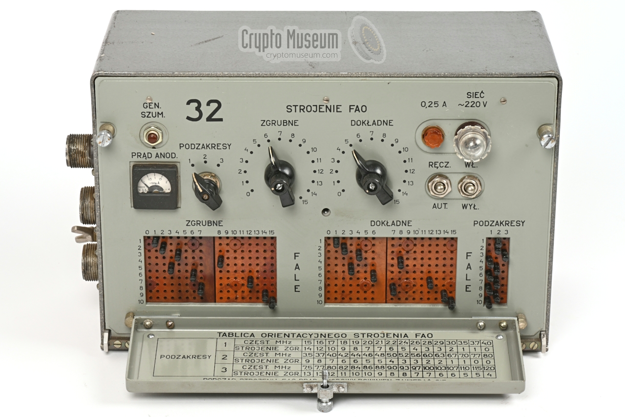
The complete FAP-device consists of two units: the antenna
(FAP-31) and a remote control unit (FAP-32). The antenna has
no controls and is connected to socket (32-Ш2) of the control
unit via a shielded 16-wire cable. Below is an overview of the
controls and connections of the FAP-32.
The device has two modes of operation: manual or automatic.
In manual mode (recommended), the upper half of the control panel is
used. It has setting for frequency RANGE (3 steps), COARSE TUNING (15
steps) and FINE TUNING (15 steps).
In automatic mode, the lower half (covered by a hinged panel) is used.
It can hold up to 10 pin-configurable presets for range, coarse and fine,
and can only be used by a compatible receiver that is connected to
connecor (32-Ш3) at the left.
The device also has a unique tuning aid in the form of a noise generator.
It can be enabled by pressing the push-button at the top left 1 and is
active as long as the button is held. Using the anode current meter
in combination with the connected receiver (tuned to the desired frequency),
the RANGE, COARSE and FINE settings should be adjusted for maximum noise
in the receiver.
Note that the anode current meter should stay between 1.5 and 1.8.
Once the optimum setting is found for the COARSE and FINE tuning controls,
the knobs must be locked by pushing them in and turning the small knob
at the centre. This activates the setting and prevents the setting from
being altered accidentally.
|
|
-
On some versions, the noise generator button is located to the right of
the ON/OFF switch.
|
|
The FAP antenna was supplied as part of the R-140M radio installation,
that was usually installed in a military shelter at the back of a
ZIL or GAZ military truck, whilst the antenna was mounted at
the rooftop of the shelter. The various parts of the radio installation
are usually identified by their number in the R-140M circuit diagram.
This number is often used as a prefix or suffix.
In this scheme, the numbers 31 and 32 are used for the FAP antenna
and its controller respectively:
|
FAP-31 Active ferrite antenna FAP-32 Remote control unit
|
|
In addition, the following R-140M
part ID may be of interest:
|
PUR-9 Receiver control unit (pre-selector) — not part of FAP
|
Both the antenna and the contoller exist in a number of variants, all of
which are believed to be compatible. These are mainly differences in the
physical construction such as paint (colour), hinges, mountings and
materials. It is currently unknown where the FAP units were manufactured,
but it is entirely possible, if not likely, that they were made by multiple
manufacturers.
Initially, all units had Russian labels on their front panels, but some units
were reworked for use in other countries. An example of this is the
Polish variant featured on this page. So far, we have recorded the following
differences:
|
- Paint
Some controllers, in particular the once used in the USSR, were painted
hamerite grey, like the one shown above. Some units
however, such as this one,
had a flat grey exterior.
- Text labels
Initially, all units had Russian labels on their front panel, but some
units – particularly the ones that were used in the Warsaw pact countries –
were fitted with an overlay
that contained text labels in the local language.
- Mounting
Some units, such as this one, had two mounting ears
at the bottom, which allows them to be mounted on a table or rack. On other
units, such as this one,
the mounting ears were omitted. Instead they had mounting holes at the rear.
- Construction
There are also differences in the mechanical construction of the cases,
such as the hinge(s) at the lower edge of the control panel. Some control
units consist of a frame with bolted-on panels,
whilst others have a bended steel enclosure.
The noise generator push-button is located above the anode current
meter, or to the right of the ON/OFF switch.
- Materials
The exterior of the early antenna units are made of
black plastic, whilst
the later ones had a polyester fibre body
and were painted in a military green colour.
|
The diagram below shows how the various units are connected together.
At the bottom left is the controller (FAP-32), which is connected to the
AC mains and – via a 16-wire shielded cable – to the antenna (FAP-31).
The RF output from the antenna is available on a 75Ω coaxial
connector, and can be fed to the input of the receiver, which is
usually in the same room as the controller.
Note that automatic tuning of the FAP-32 controller is only
possible if the Russian ПУР (PUR) control unit of the
R-140M radio set is installed between the antenna output and the receiver,
and an 11-wire cable is connected between the PUR (9-Ш17)
and the FAP controller (32-Ш3).
When operating the PUR, it can select any of the 10 pin-configurable
presets of the controller (FAP-32). For this to work, the 10 presets have to
be configured carefully, and must correspond to the frequency bands used
by the PUR and the receivers that are connected behind it. For amateur use,
this option should be ignored and the MAN/AUTO
switch should be set to manual.
|
The active ferrite antenna is housed in a plastic or polyester fibre
enclosure that could be mounted to a wall or – more typical – at the
rooftop of a (radio) vehicle. It can be used in horizontal as well
as vertical orientation and has a blurry (wide-angle) directivity.
Inside the device is a high-gain low-noise valve-based pre-amplifier.
The image on the right shows the polyester fibre variant, complete
with two L-shaped mounting brackets.
|
|
|
|
The active antenna is controlled remotely, by means of the
remote control unit (RCU) shown in the image on the right. This
unit also contains the mains PSU that supplies the LT and
HT voltages for the antenna's valve-based amplifier and 27V
for the relays.
|
|
|
Only the control unit (FAP-32) has to be connected to the mains.
It passes the necessary LT and HT voltages to the antenna unit, via the long
interconnection cable (see below).
The 220V AC mains should be applied to the 3-pin connector at the
side of the control unit. The image on the right shows a suitable mains cable.
➤ Wiring details
|
|
|
Each FAP came with a small carton box with spare parts for the antenna unit
(FAP-31). The image on the right shows the one that was supplied in
Czechoslovakia. It contains two valves (6С3П-ДР, 6С4П-ДР) and one
spare relay.
The box shown here was found inside one of the control units we had under
investigation in August 2021. It was still sealed at the time.
|
|
|
Below is the circuit diagram of the antenna unit (block 31), which consists
of a balanced ferrite antenna pair, a tuning network and a balanced
amplifier. At the bottom right are 12 relays that can be driven by the
control unit, via a 16-wire multi cable that terminates in connector 31-Ш1.
|
| |
FAP antenna circuit diagram
|
At the top left are the two ferrite antennas (A1, A2), each of which has two
coils (L1-4). The four coils can be connected in series or parallel
in three possible configurations, under control of relays Y1-4, which in
turn are controlled by the range selector on the control unit. The remaining
relays (Y5-12) operate the tuning network, which consists of 8 caparacitors
that can be used in various combinations, under control of the coarse and
fine selectors of the remote control unit.
|
| |
Two-stage amplifier in cascode configuration
|
At the top right is a two-stage balanced amplifier. Each arm consists
of two valves in cascode configuration. The first stage (V3, V4) is a
regular amplifier in grounded-cathode configuration, whilst the second stage
(V1, V2) is a current amplifier in grounded-grid configuration. It converts
the high impedance signal from the first stage into a low impedance output,
that is passed through transformer Tr1 to the output socket (31-Ш2).
Note that the output impedance is 75Ω.
An extra winding on the second ferrite antenna (L5) is part of a noise
generator around D1, C1 and R1. It can be enabled by a push-button on the
controller and injects white noise into the antenna circuit. It can be used
as a tuning aid when adjusting the range, coarse and fine tuning selectors on
the control unit. The optimum setting produces maximum noise in the receiver.
➤ View the original circuit diagram 1
|
|
-
Note that the original circuit diagram contains several errors
and should not be relied upon.
|
The FAP-31 is a pure H-field antenna. It is only sensitive to the magnetic (H)
component of an electromagnetic wave and behaves like a so-called small-loop
antenna [6]. By using a ferrite core, the magnetic field in the loop is
increased (concentrated), whilst the size is greatly reduced.
In the FAP-31, two separate ferrite antennas are used, that are wound in
such a manner that they provide a differential signal that can be fed to a
balanced valve-based pre-amplifier. The two ferrite antennas are placed
several inches apart, to avoid flux competition. 1
The coils of the two ferrite antennas can be connected in series or parallel
in various configurations by means of four relays, so that it can be adapted
for the three frequency ranges.
Another eight relays are used to connect one or more capacitors in
parallel to the coils, so that the antenna can be made resonant for the selected
sub-band. This has the following advantages:
|
- Pre-selection of the desired (sub)band, resulting in a stronger signal
- Suppression of strong signals in adjacent bands
|
The pre-amplifier consists of a valve-based
differential amplifier in cascode configuration.
The input impedance is high (R2 + R3 = 480 kΩ)
to ensure a high Q-factor when tuning for the desired frequency.
The Q-factor is almost solely determined by the windings and the properties
of the ferrites. For the latter, ferrite composite is used with a rather high
permeability of approx. 200.
We assume that this was done to obtain the highest possible
Q-factor and, hence, a good pre-selection for the connected receiver,
at the cost of reduced sensitivity at higher frequencies.
For this to work properly, the receiver should have an (adjustable) attenuator
and preferably a good large-signal behaviour, as the pre-amplifier in the FAP
antenna can produce quite a strong signal. This is the main reason why for
(military) monitoring and communications receivers, large-signal behaviour is
often more important than sensitivity.
The FAP is is very good at suppressing interfering signals in the
near-field, both magnetically (H-field) and electrically (E-field).
Due to the parallel emplacement of the two ferrite antennas,
a near-field magnetic wave (H) will arrive at the antennas at different
phases, thereby effectively cancelling them out (or at least attenuating them).
The signal from a far-field source on the other hand, arrives at both
antennas at equal phase, resulting in a higher input to the amplifier.
By design, small-loop antennas (in casu ferrite antennas) are
sensitive only to the magenetic (H) component of the incident wavefront,
and are nearly immune to the electric (E) component. Any near-field
E-components that are coupled directly into the coils (e.g. due to stray
capacitance), result in a common-mode signal that gets rejected by the
differential-mode amplifier.
|
|
-
The ferrite core changes the direction of the magnetic field lines
in its immediate vicinity, so that the field inside the coil becomes
stronger (more concentrated).
If another ferrite antenna is placed close to it, that antenna can therefore
'steal' some of the flux, resulting in reduced performance.
|
|
The antenna unit measures 540 x 240 x 102 mm and weighs approx.
7 kg. 1 Depending on the year it was manufactured (and probably also
the manufacturer), it was housed in a black plastic or grey polyester
fibre enclosure, that consists of two parts: a bottom shell and a top
shell, held together by 16 bolts, washers and nuts. In between the two
shells is a watertight rubber gasket.
|
After removing the 16 bolts, the top case shell can be removed and the
interior is exposed. All parts are bolted to the bottom case shell and
can be accessed from the top as well as via a sealed removable window
at the bottom of the unit.
...
|
|
|
-
Average weight depending on version (plastic or polyester fibre) and
whether or not the mounting brackets are present.
|
|
The control unit is housed in a metal enclosure that measures approx.
327 x 205 x 150 mm and weighs approx. 7 kg. Getting access to the
interior is simple, and requires just the two locking bolts to be
loosened, after which the hinged front panel can be lowered as shown
above. It is also possible to remove the rear panel of the case to
get access to the solder side of the main PCB.
|
All controls are mounted to the
hinged front panel and are wired
in a single bundle. At the right is the mains transformer, which is
bolted to the bottom of the case. At the rear is a large Printed Circuit
Board (PCB) that holds the power supply unit (PSU) and a large
diode matrix.
At the left are the three sockets for connection to the mains, antenna
and receiver respectively.
...
|
|
|
In August 2021 we were given the opportunity to evaluate two FAP antenna
units that were in an unknown state. One unit was manufactured in 1979.
Its antenna is housed in a black plastic enclosure and the control unit
has a flat grey body with mounting ears. The other antenna was made in 1983
and has a grey polyester fibre body, whilst its controller has a grey hamerite
case.
...
|
A major problem with the FAP antenna, is the fact that it has a 75Ω
output, whilst most regular receivers have a 50Ω input. This can
be solved by replacing the output socket and adding a small resistor network
as shown in the diagram below. It gives an insertion loss of approx. 5.7dB,
but given the strong signal produced by the antenna, this should not be
considered a problem.
As the resistor values for R1 (43.2Ω) and R2 (86.6Ω) are not
readily available, they can be approximated by substituting R1 for 47Ω
// 470Ω (parallel), and R2 for 100Ω // 680Ω.
|
No circuit diagram All cables missing - Screws missing from antenna enclosure
Several wires broken from ferrite antenna coil - Plastic antenna enclosure no longer watertight
- Mains transformer suitable for 220V AC only
Uncommon Russian 75Ω coaxial connector
|
|
The control unit (FAP-32) must be powerd by the 220V AC mains,
which was the common mains voltage in continental Europe at the time.
It cannot be configured for other mains voltages, so there may be
difficulties using it on the current European mains voltage of 230V AC. 1
|
- 220V AC (1)
- 220V AC (2)
- Ground (chassis)
|
|
-
Voltages of 240V or even higher are no exception in continental Europe
today. This may cause the mains transformer of the control unit to
saturate and potentially overheat and breakdown.
|
|
Below is the pinout of the 32-Ш2 connector at the left side panel
of the control unit. It is intended for connection to the ПУР (PUR)
preselector that was part of the R-140M radio installation. It can be used
in combination with any short wave receiver in this installation.
When the ПУР (PUR) preselector is not present, this connector is unused.
|
- Preset 1
- Preset 2
- Preset 3
- Preset 4
- Preset 5
- Preset 6
- Preset 7
- Preset 8
- Preset 9
- Preset 10
- Ground (0V)
- unused
- unused
- unused
- unused
- unused
- unused
- unused
- unused
|
|
|
|
Antenna control
32-Ш3 → 31-Ш1
|
|
|
The 19-pin connector closest to the bottom on the left side of the
control unit (32-Ш3), and is intended for connection to the antenna.
It requires a male/female cable, which should be wired 1:1.
Note that only the first 16 pins are used and that pin 13 carries the +270V.
This cable passes the data signals to drive the relays (Y1-12) using 27V
negative logic. To activate a particular relay, the corresponding pin
should be driven low (0V). Note that the cable also carries the voltages
from the PSU – inside the controller – to the antenna, and that special
precautions must be taken for the +270V HT line.
Pins 17, 18, and 19 and not used.
|
- Relay Y1, Y2
- Relay Y5
- Relay Y6
- Relay Y7
- Relay Y8
- Relay Y9
- Relay Y10
- Relay Y11
- Relay Y12
- Noise enable
- ~6.3V (LT1)
- ~6.3V (LT2)
- +270V (HT)
- Relay Y3, Y4
- Ground (chassis) (0V)
- +27V
- unused
- unused
- unused
|
|
The RF output from the antenna is available on connector 31-Ш2.
This is a 75Ω coaxial connector designated CP75-166F. As 75Ω
is a very unusual impedance for a receiver, it is recommended to alter
the output ciruit of the antenna and replace the socket by a 50Ω one.
➤ Modification
|
Device Active H-field ferrite antenna Purpose High-gain mobile HF reception Model FAP Manufacturer ? Frequency 1.5 - 12 MHz 1 Ranges 3 Course tuning 15 steps Fine tuning 15 steps Control Manual (local) / Automatic (remote from PUR) Presets 10 Tuning With built-in noise generator Valves 4 (see below) Power 220V AC mains LT voltage 6.3V AC / 1.5A HT voltage +270V Relays +27V Dimensions Antenna 540 x 240 x 102 mm, Controller 327 x 205 x 150 mm Weight Antenna 7 kg, Controller 7 kg
|
- 2 × 6С3П-ДР (6S3P-DR) — equivalent: EC86
- 2 × 6С4П-ДР (6S4P-DR) — equivalent: EC86
|
-
In practice, most units can be used up to 14 or even 16 MHz.
|
- User: Maciek1, "Zachcialo mi sie FAO" czyli pytania o FAO od R140
Forum Trioda, 26 January 2016 - 22 April 2016.
➤ English translation
- User: 1428, FAP and FAP control panel from R-140M (ferrite antenna)
Forum Radioscanner.ru, 10 August 2009.
➤ English translation
- Alexander Nikitenko, Ferrite FAP antenna. Ferrite MONSTER
Demonstration of the FAP antenna (in Ukrainian language).
YouTube, RadioBlog, 28 February 2018.
- Joe Bell (G4PMY), Russian Military Radio Station R-161 (part 3)
YouTube, G4PMY, 8 December 2007.
- Joe Bell (G4PMY), The R-161 radio stations
The VMARS Newsletter, Issue 14, December 2000.
- Wikipedia, Loop antenna
Retrieved August 2021.
|
|
|
|
Any links shown in red are currently unavailable.
If you like the information on this website, why not make a donation?
© Crypto Museum. Created: Wednesday 11 August 2021. Last changed: Wednesday, 05 November 2025 - 12:00 CET.
|
|

|
|
|