|
|
|
|
|

|
|
Philips Siemens ← Aroflex
The device measures 326 x 143 x 73 mm, and has two 8 mm pins at the bottom
that mate with two mounting holes at the corners of the rear
edge of the Crypto Module's die-cast chassis.
At the lower edge are six green DIL sockets, that allow the TESTSET to
take over the functions of the Aroflex Processor Board.
To the right of the centre is a two-digit thumbwheel on which the desired
test program can be selected (subject to the instruction manual).
The red button at the right is used to start the test.
At the top left are 11 red LEDs that show the progress of the test.
|
|
|
|
When servicing the Crypto Module of an Aroflex, the T-1000
should be placed on its left side, after which all eight hex bolts
in the bottom of the Crypto Module should be loosened.
Once that is done, the hinged Crypto Module can be lowered, whilst
the cabling to the T-1000 stays intact.
Note that a hidden tamper switch
will cause any cryptographic keys to be purged at this point.
|
Remove the six ribbon cables from the Processor Board, in such a way that the
Processor Board is no longer wired. Two cables remain connected to the
Interface Board (left), two to the Mixer Board (centre)
and two to the Memory Board (right).
The ribbon cables will be reused in a moment.
Next, locate the two large mounting holes at the corners of the rear end
of the Crypto Module, and fit the TESTSET to these holes, with the front
panel facing the interior,
as shown in the image on the right. Sockets X1-X6 should now line up
with the ribbon cables of the Processor Board.
|
|
|
|
Now, connect the ribbon cables from the Interface, Mixer and Memory Boards
to the sockets X1 - X6 of the TESTSET. The TESTSET has now effectively
taken over the role of the Processor Board of the Crypto Module.
By running the appropriate test, the TESTSET can be used to find faults on
any of the Crypto Module's boards,
with the exception of the Processor Board itself (as it is unwired).
|
UA-8494/00 Initial version with thumbwheels UA-8494/02 Push-buttons instead of thumbwheels
|
|
The US-8494 TESTSET was part of a complete diagnotiscs kit, that was supplied
in two aluminium transport cases: one with a number of spare parts and
replacement boards, and one with the test equipment for carrying out depot
repairs. The latter contained the following items:
|
- Case for Test Set with Accessories UA-8511/10
- Test Set UA-8494
- Extractor 8122 060 32950
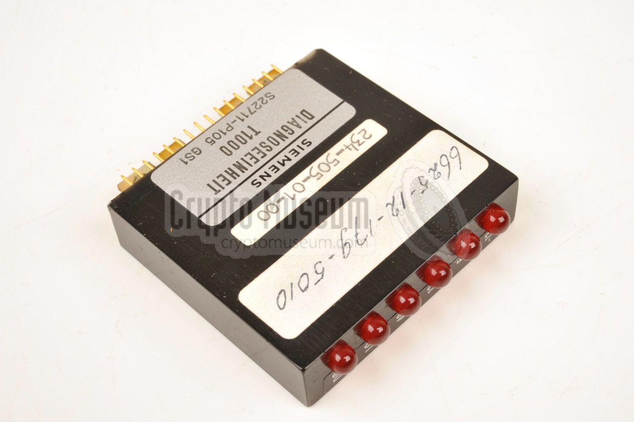
- Diagnosis Unit Siemens DIAG S22711-P105
- Line power supply for simulating line-connected mode
- Set of extender cables, 45 cm each
|
|
The interior of the UA-8494 can be access by removing four large bolts
along the short sides of the front panel, and lifting the front panel from
the case shell. All parts are mounted to the rear side of the front panel,
and consists of a large PCB and a smaller one that is fitted on extenders.
|
The larger PCB is mounted directly to the rear of the front panel, and holds
the sockets, controls and indicators that are visible from the front of the
device.
The smaller PCB holds an AMD 8080 microprocessor and is in fact identical
to the Processor Board of the Crypto Module itself.
The test software is held in
an EPROM that is located on the larger PCB.
|
|
|
|
|
|
Any links shown in red are currently unavailable.
If you like the information on this website, why not make a donation?
© Crypto Museum. Created: Saturday 09 November 2019. Last changed: Friday, 23 December 2022 - 12:39 CET.
|
 |

|
|
|


