|
|
|
|
|

|
|
USSR Rotor Fialka Wiring →
At the heart of each M-125 (Fialka) is a drum with 10 different
electromechanical cipher rotors (wheels)
that move in an irregular manner
when entering a message.
Each rotor has 30 contacts at either side and is identified by a letter
of the Russian alphabet, as follows:
A collection of 10 such unique rotors is called a rotor-set,
or just: set.
Each rotor is wired differently,
and each country of the former Warsaw Pact
had its own rotor-set (wired differently for each country).
Such a country-specific rotor set is called a series, identified
by a number and the letter 'K' (e.g. 3K for Poland).
Direct communication between Warsaw Pact nations was strictly prohibited
during peacetime and any messages had to be sent via the Russians.
Only in the event of war with the West, a common rotor-set
(known as the 0K-series) would be released.
Each rotor has 30 electric contacts at either side. The right side of the
rotor is called the input, whilst the left side holds the
output contacts. The input contacts are connected to the output
contacts in a
scrambled manner.
As there are 30 contacts, each rotor has 30 possible positions.
Each position is marked with a letter of the Russian alphabet
on the index ring, in this order:
А Б В Г Д Е Ж З И К Л М Н О П Р С Т У Ф Х Ц Ч Ш Щ Ы Ь Ю Я Й
The 10 different rotors are placed on a spindle in the order dicatated
by the daily key, similar to the rotors of the
German Enigma.
A retaining clip is used to keep the rotors locked to the spindle.
The spindle is then placed inside the machine, after which the
entry disc and the reflector are locked. After setting the rotors
to their initial position, the machine is ready for use.
There are two different rotor types: fixed and
adjustable.
The fixed rotors were introduced with the first Fialka
machines in 1956, whilst the adjustable rotors were supplied as an upgrade
from 1978 onwards. They are known as the PROTON-2 upgrade.
The adjustable rotors are commonly found with the later
M-125-3 Fialka models, whilst fixed rotors remained in use with the older
M-125 models. Although it is technically possible to use the adjustable
rotors on the older M-125 model, no proof has been found so far to indicate
that this was actually done.
|
Below are the original rotors that were distributed with the
M-125 machines when they were first introduced in 1956. They were also
supplied with the first M-125-3 machines when they were released in the
mid-1960s.
As these rotors are not adjustible, they are called the fixed rotors.
The non-metal parts are made of brown bakelite with a fibre-strengthened
outer ring with gaps.
Each rotor has 30 disc-shaped contacts at its left side and 30
spring-loaded contact pins on the right side. With each machine, a unique
set of 10 different rotors was supplied, marked with 10
letters of the Russian alphabet as described above (Rotor ID).
The number is printed at the right side of the disc; in the example
below this is the letter 'A'.
As the rotors are wired differently for each country,
a series identification (Series ID) is also printed at the right side.
In the example below this is '3K', which indicates that this rotor
was used with the Polish Fialka variant.
Inside the rotor, the 30 contacts at the left are connected to the
contacts on the right in some scrambled manner. This
wiring can not be changed in the field.
At the outer rim of each rotor are a number of metal pins.
These pins control the irregular stepping of the rotors and are called
the Advance Blocking Pins.
Each rotor has a different number of such pins at different locations.
Each machine was supplied with two complete sets of rotors:
an operational one and a spare one. The operational set usually
resided inside the machine and had black lettering on the index ring.
The spare rotors had red lettering and were kept in an metal container inside the dust cover.
|
|
|
Adjustable rotors
PROTON-2
|
|
|
In 1978 a new operating procedure for the Fialka was introduced,
known as PROTON-2.
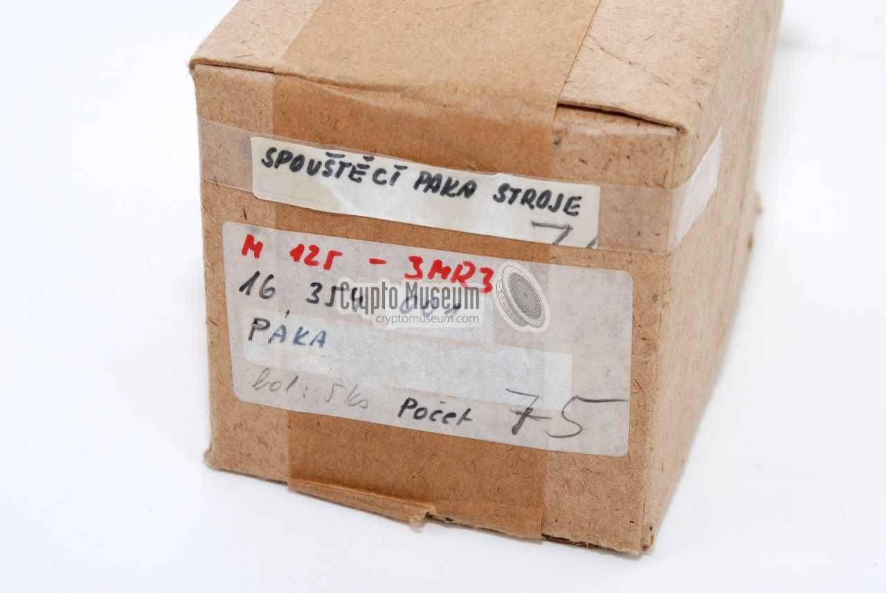
At the same time a new set of cipher rotors was issued.
For each individual country, the new PROTON-2 rotors were prepared
by the Russians well in advance of the actual release date.
They were shipped in carton boxes, such as the one
shown here,
which was discovered in Czechoslovakia.
The new rotors were much more complex than the earlier
ones, and can be adjusted in a number of ways.
This greatly increases the maximum number of permutations
and, hence, the strength of the cipher, without making any
modification to the machine whatsoever. In their basic setting,
the adjustable rotors are compatible with the earlier fixed rotors.
Although they can theoretically be used in the
older M-125, no evidence has been found to
indicate that this was actually done in practice.
We therefore assume that the adjustable rotors belong to the M-125-3 machines.
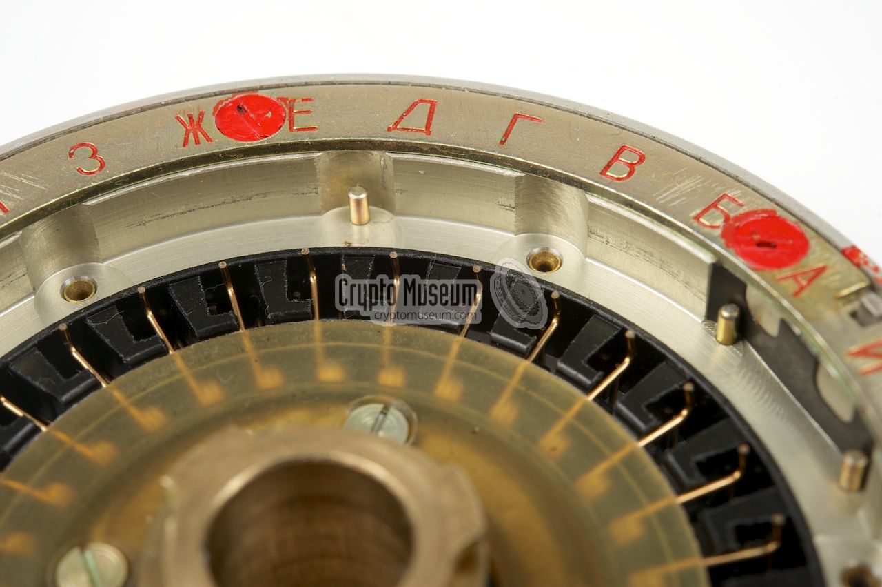
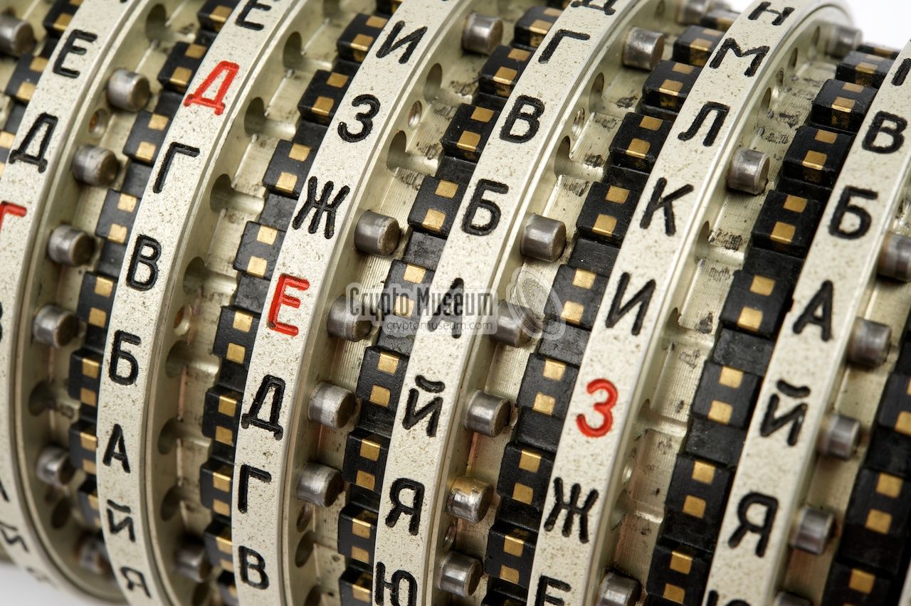
The rotors that normally reside inside the machine,
have black lettering on the index ring,
with one letter in red to identify the rotor (Rotor ID).
For example, on rotor 'A' the letter 'A' on the index ring is painted red,
as shown in the image below.
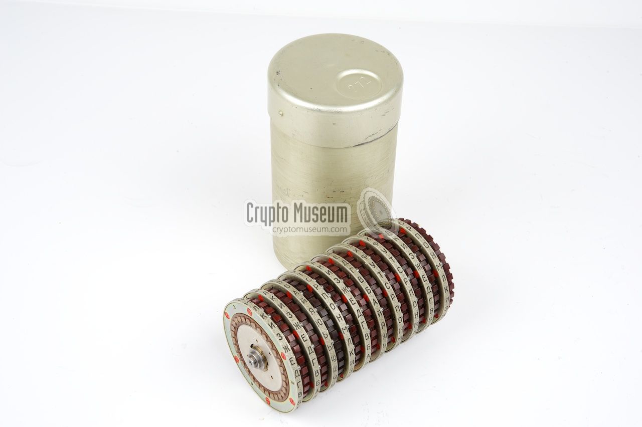
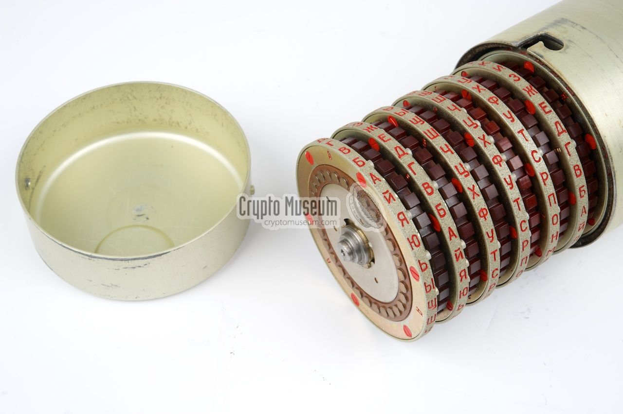
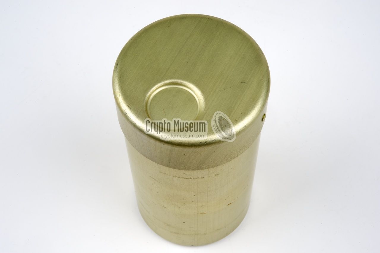
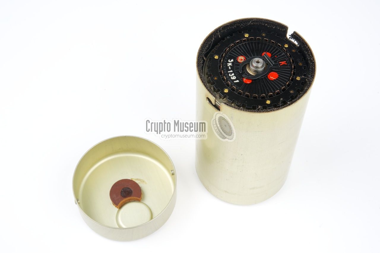
Inside the dust cover of the machine is a spare set of rotors,
stored inside a cylindrical
aluminium container.
The letters on the spare rotors are all red, except for the letter that identifies the
rotor, which is black.
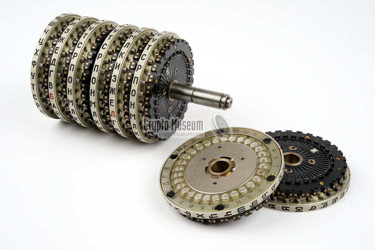
On the new adjustable rotors, the letter index ring is now movable,
much like the Ring Setting (German: Ringstellung) of the
Enigma.
The ring is locked in place with the index release notch.
Secondly, the
wiring core can be now removed
(see below)
and can be re-inserted in 30 different orientations,
plus 30 more if the core is flipped around (side 2 up).
Furthermore, the wiring core of a particular rotor can be
placed inside any of the other rotors as well.
|
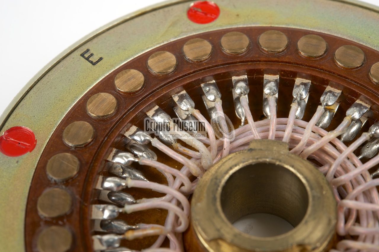
In order to accomodate the
removable wiring core, the thick
circular spring-loaded contacts of the fixed rotors have been replaced by
very thin U-shaped contacts
that are made of spring-wire. On the
inside of the rotor,
the spring-wire is bended in such a way, that it makes contact
with the reverse side of the core. The image on the right shows the
interior of an adjustable rotor of which the wiring core has been removed.
These contacts have to be handled
with care, as they are easily damaged. Spare springs were usually supplied
with each maintenance kit.
|
|
|
If the correct core (i.e. the core with the same ID as the
rotor) is inserted into the rotor, with side 1 up (i.e. side 1
visible from the left side of the rotor) and the white index line
is lined up with the letter A on the index ring,
and the index ring is set at the letter A,
the rotor is backward compatible with the corresponding fixed rotor.
This setting is known as the basic rotor setting.
|
|
|
Disassembly of an adjustable rotor
|
|
|
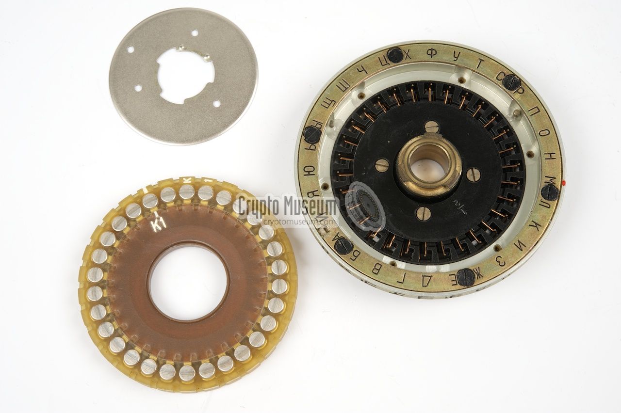
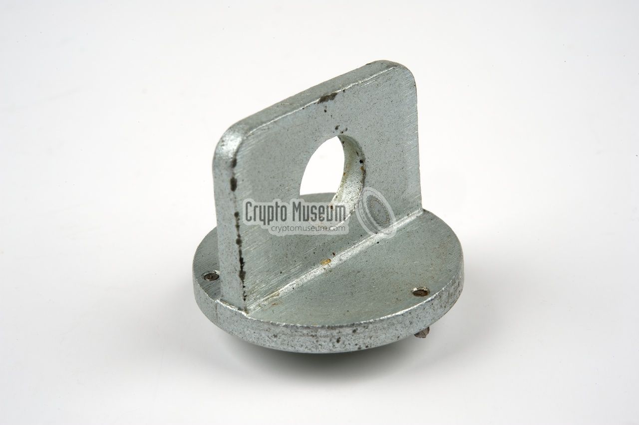
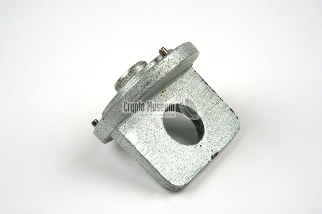
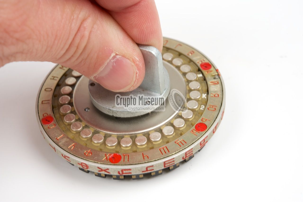
This image below shows how the adjustable PROTON-2 rotors
can be disassembled. Originally, a
special tool was supplied to
open the rotor, but this can also be done manually by pressing the center
disc down with both thumbs, and then rotating it until the center
disc comes off. The wiring core can then be removed.
Assembly of the rotor works just the other way around.
By flipping the core around, the wiring is effectively mirrored.
This greatly increases the maximum number of settings. To make
it even more complex, the core can be moved to another rotor, that
has its Advance Blocking Pins at different positions.
All this was part of the daily key.
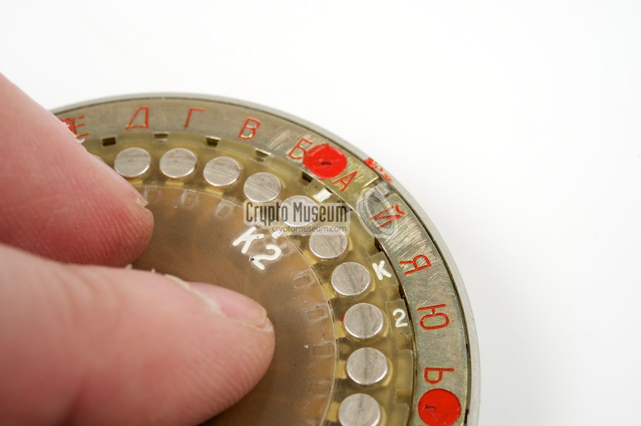
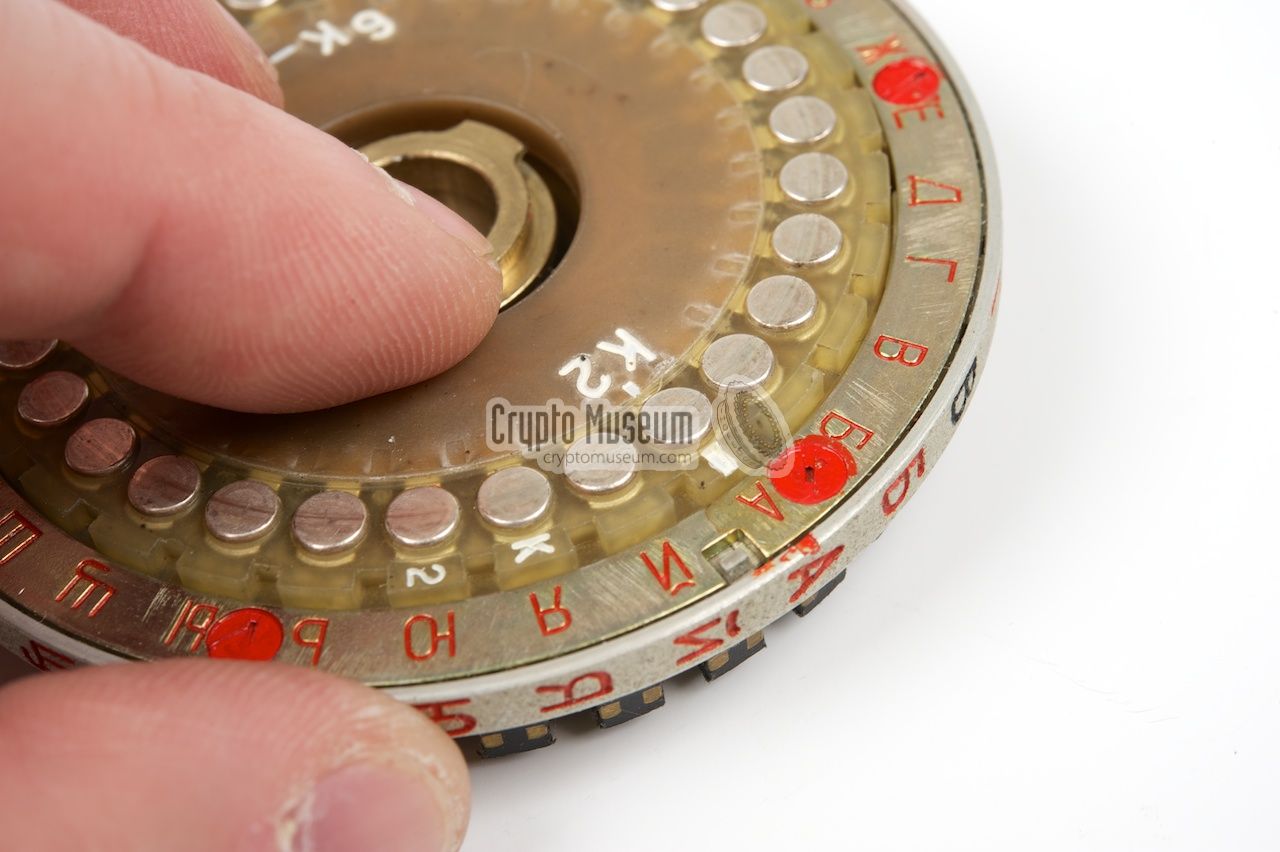
The Core ID and the Side ID (1 or 2) are printed in white in the
centre part of the core, but also at the outer rim at both sides.
This way the Core ID and the side number are
always visible, even when
the rotor is reassembled again and the metal centre disc covers
the text on the core.
|
The drawing below shows which parts of the PROTON-2 rotors can be
adjusted and how it affects the setting of the daily key. For each day,
a small printed card was supplied in a sealed bag. A two-digit number
in the top right corner of the card identified the day of the month (e.g. 14).
The card further contained 5 lines with 10 Russian characters each.
The first line (1) gives the order in which the rotors should
be placed on the spindle. Line (2) gives the setting of the
index ring. The next line (3) tells us which wiring core
should be used in each position, whilst line (4) shows which
side of the core should be visible. Finally, line (5)
defines the position of the white index line of the wiring core.
Once all these settings have been carried out, the daily key is set.
|
|
|
Manufacturing differences
|
|
|
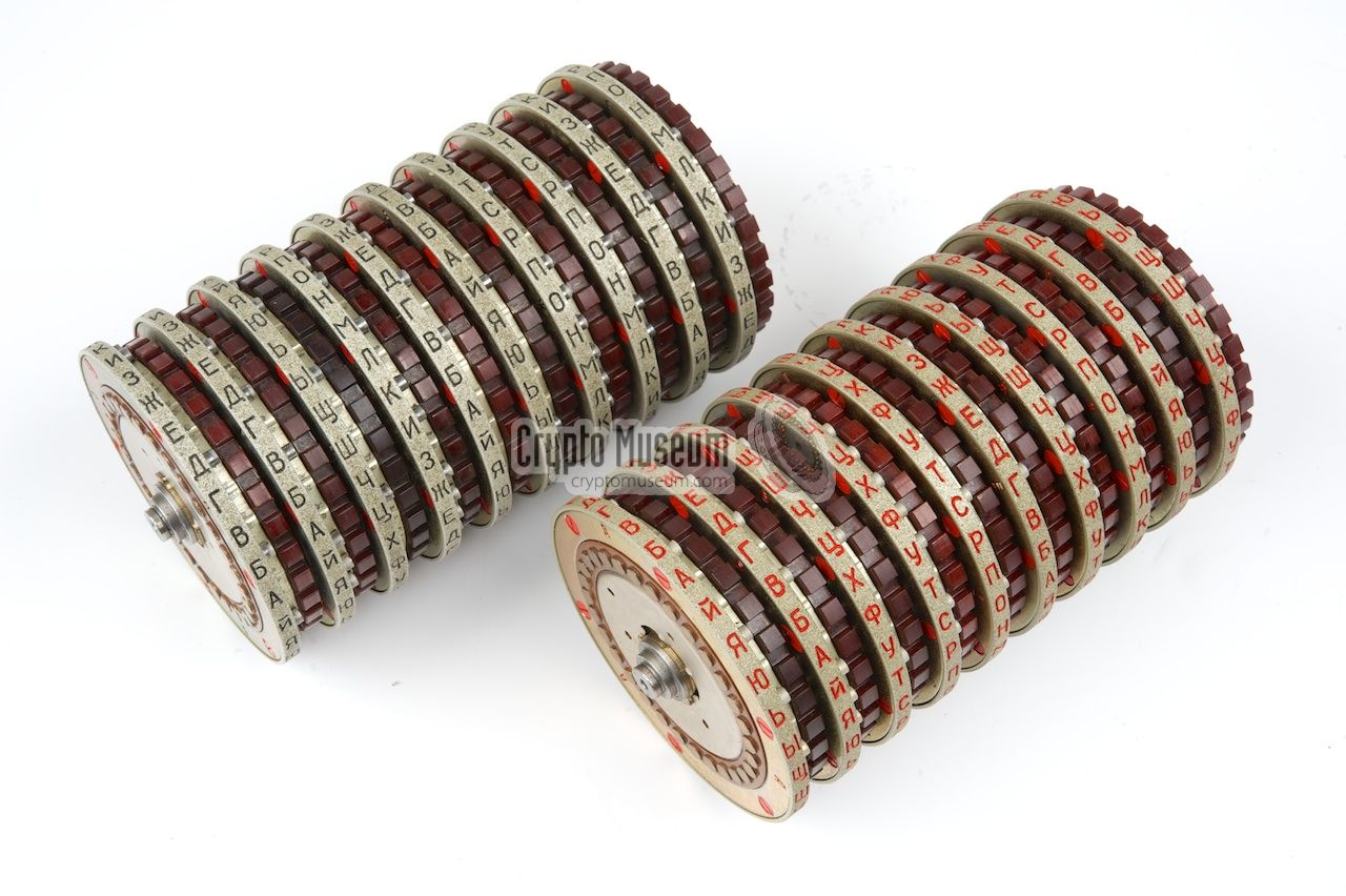
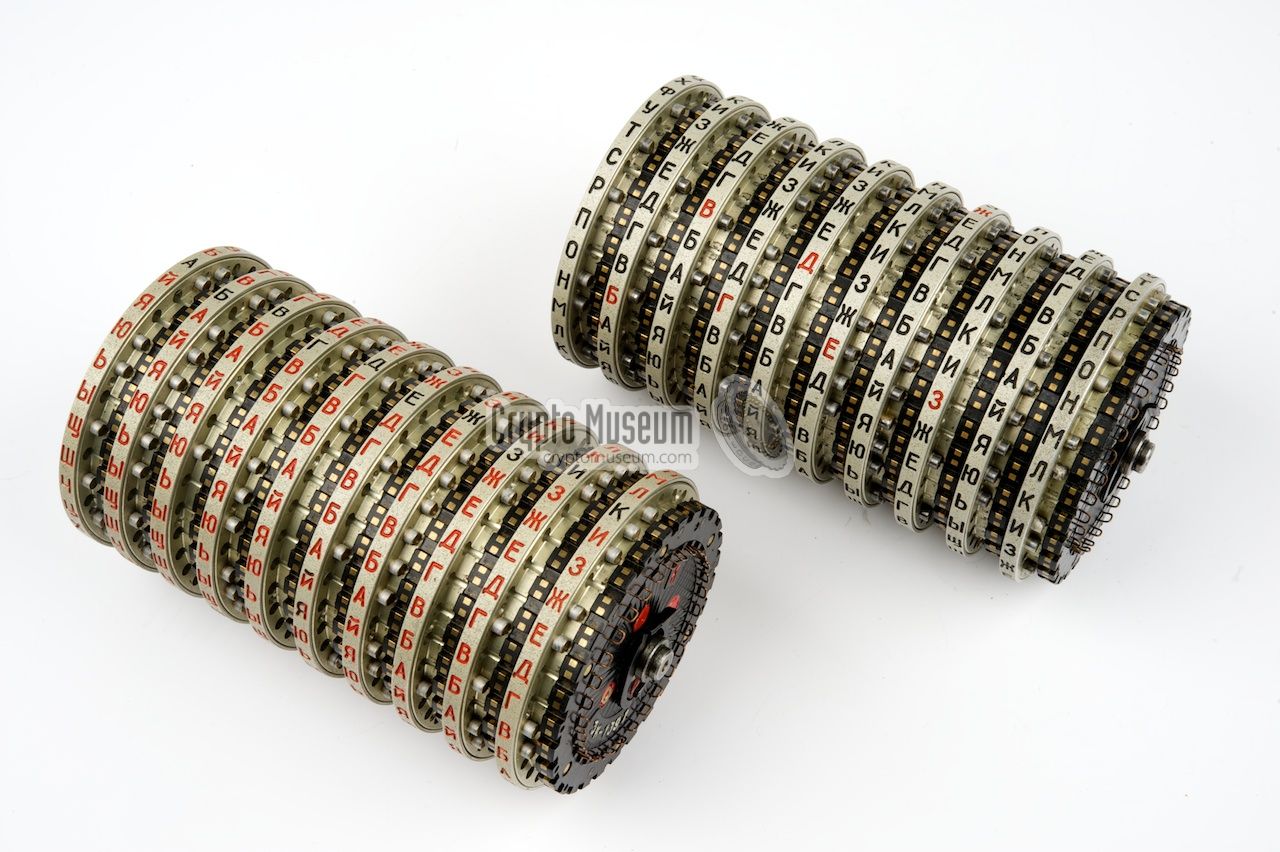
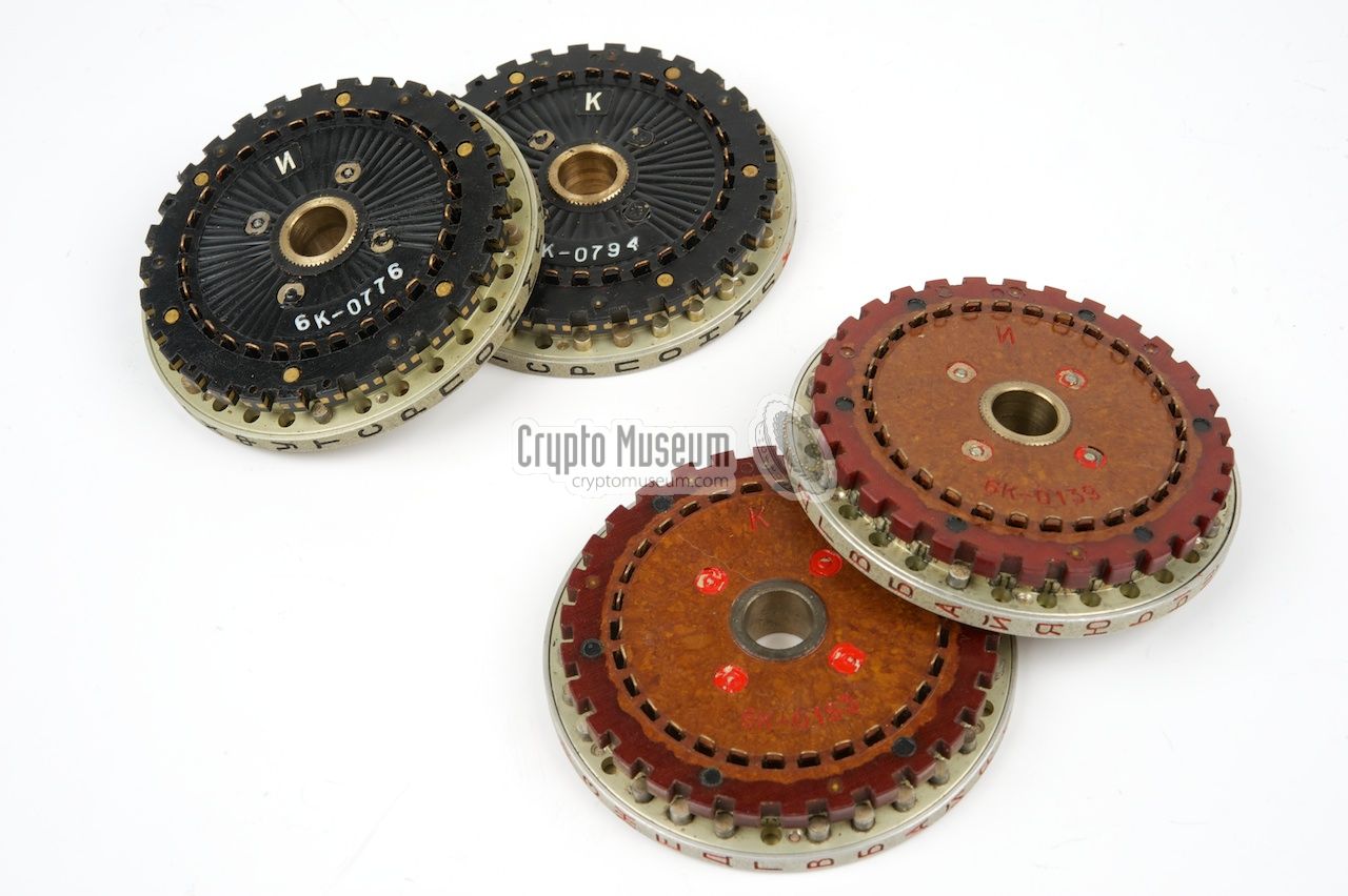
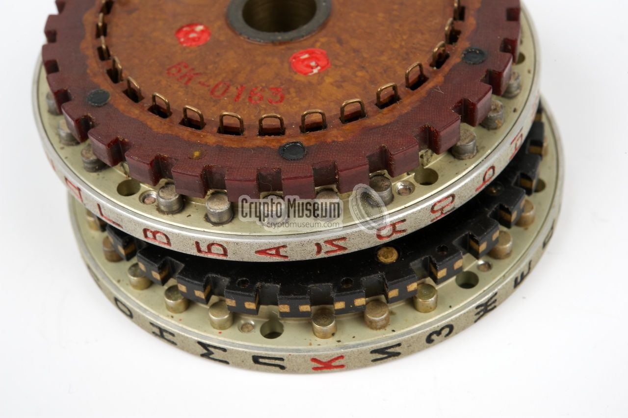
There are two known manufacturing variants of the adjustable PROTON-2
rotors. Initially, the non-metal parts of the rotors were made of
brown bakelite (phenol formaldehyde resin), one of the first plastics.
These rotors are generally known as the brown rotors.
When polymer plastics became mainstream, the production process was
changed and from then on the non-metal parts were made of reinforced
black plastic. These rotors are commonly called the black rotors.
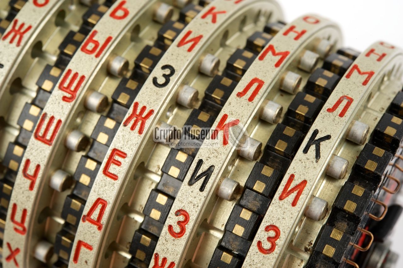
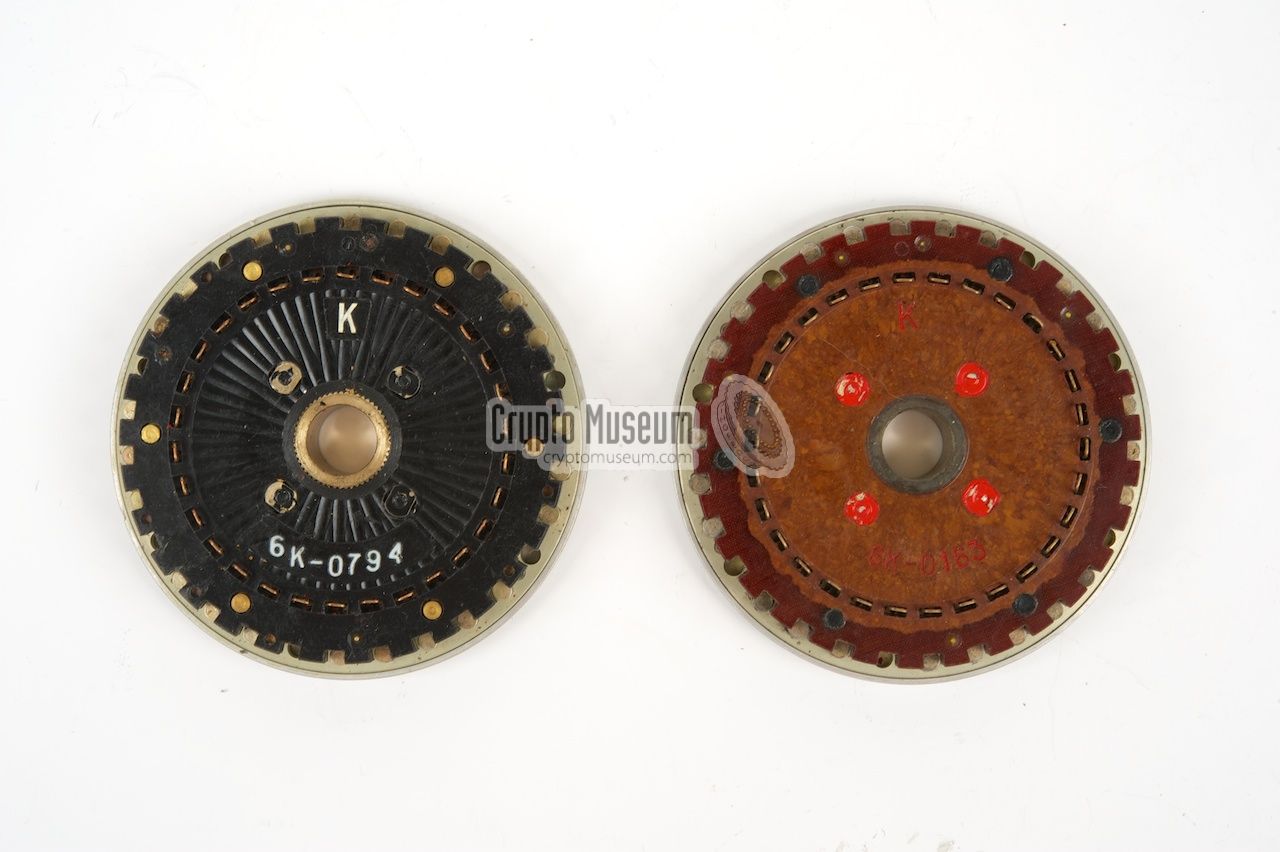
In the image above, both types are shown side-by-side. The bakelite
rotors (right) have a fibre-strengthened outer rim (i.e. the transport
ring with the gaps). With the plastic rotors, the transport ring is
reinforced with metal stubs, as is clearly visible in
this close-up. More detailed images of the
manufacturing differences can be found below. The first four images
show the adjustable and fixed rotors side-by-side, whilst the last
four images show plastic and bakelite adjustable rotors side-by-side.
All types were available with either black or red lettering.
|
|
|
|
Any links shown in red are currently unavailable.
If you like the information on this website, why not make a donation?
© Crypto Museum. Created: Sunday 06 July 2014. Last changed: Saturday, 15 July 2023 - 06:39 CET.
|
 |

|
|
|