|
|
|
|
|

|
|
Crypto AG Voice BND CIA CRYPTOCOM →
|
|
Hagelin CRM-008
HC-230 / HC-235
|
|
|
The device – previously known as the CV-008 – came
in two versions: civil and military, each of which were available in
a number of variants.
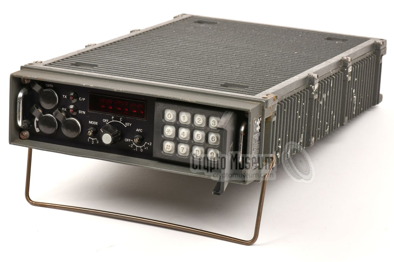
The models were later re-designated HC-230 (civil) and HC-235
(military). The image on the right shows the military version, which was
housed in a ruggedised aluminium enclosure.
The device was intended for secure speech over regular analogue voice
circuits, such as telephone lines and narrowband HF radio channels,
that were unsuitable for true digital encryption devices, due to the limited
bandwith available.
|
|
|
Compared to other voice scramblers of the era
— most of which were simple
frequency-domain only scramblers
(inverters), or
time-domain only scramblers (rolling code) —
the CRM-008 (HC-230) has the advantage that it scrambles both in the
time and frequency domain simultaneously, although the latter is
restricted to just two frequency bands, known as low and high
(or A and B).
CRM-008 (HC-230/235) was introduced in 1975, as a complementary product to the
wideband CSE-280 voice encryptor,
that is housed in a nearly identical enclosure (but which is a
true digital encryption device).
The cryptologic of both products was developed by
ZfCh, in such a way that it was readable 1
by Western intelligence services.
One of the known customers of the device was the Argentine Navy, who
used it during the Falklands War of 1982 [2].
The device was succeeded in the early 1980s, by the much smaller
HC-250.
Note that all scramblers are inherently insecure.
|
 |
-
The term readable means that the algorithm
could be broken by ZfCh.
Also known as friendly or insecure or exploitable.
In contrast:
algorithms that are not breakable by ZfCh,
are called unfriendly or unreadable.
|
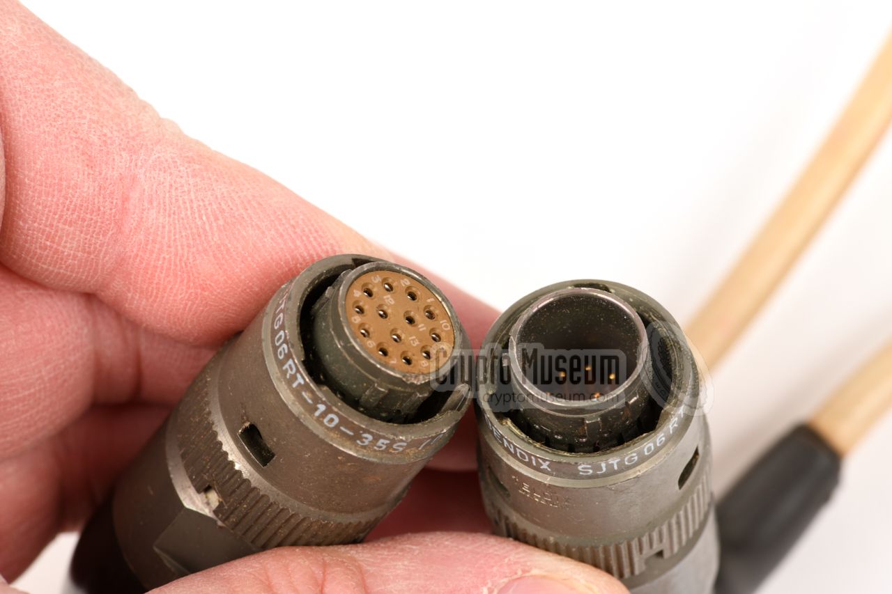
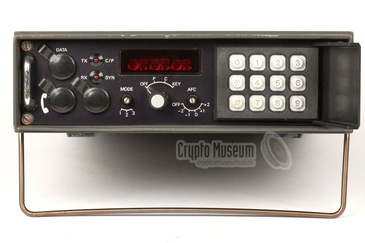
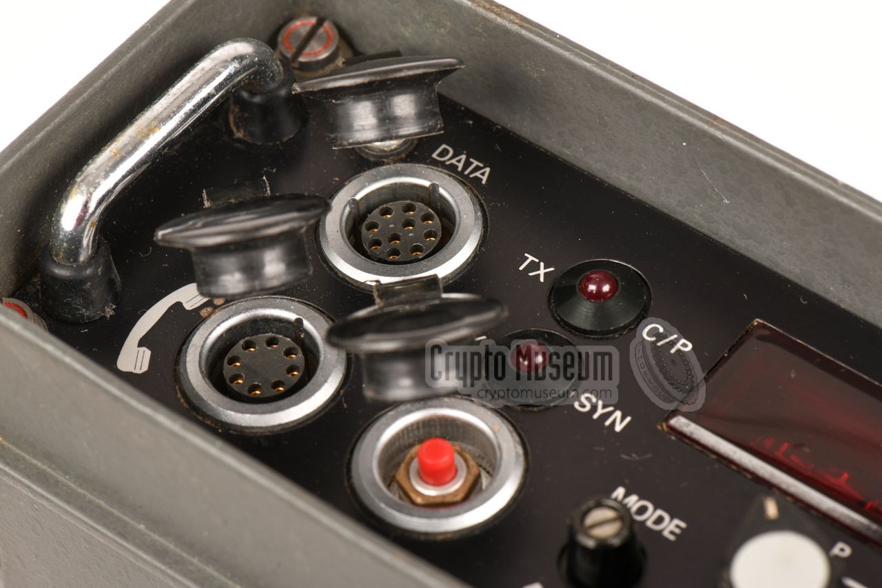
All controls and connections – with the exception of the power input – are
located at the front panel. All connections are via (expensive) LEMO
plugs.
The device is powered by a DC voltage between
10 and 30V, which should be applied to the
4-pin LEMO socket at the rear.
This can be supplied by the battery of a car (12V) or truck (24V), or
by an external power supply unit (PSU).
The front panel can be divided into three sections: (1) the connections
to the outside world – located at the left – the MODE selectors and the
display at the centre, and a 12-button keypad for
entering the cryptographic key
– protected by a plastic door – at the right. In case of emergency,
the RED push-button
(under one of the plastic caps) should be pressed to purge the keys.
|
- CRM-008-001
Mobile version powered by 10 to 30V DC and connected to the outside world
via with a 4-wire audio interface. The device featured here is of this type.
- CRM-008-002
This version appears to be physically identical to the CRM-008-001,
so it was probably a later hardware variant, or a country-specific
variant. Previously known as CV-008.
- CRM-008-007
Desktop version with built-in AC power supply unit and telephone
adapter circuitry for connection to standard 2-wire PSTN lines.
This unit is higher than the mobile version.
- HC-230
Desktop version. Believed to be a later designator of the CRM-008-007.
- HC-235
Military variant in ruggedised enclosure.
Believed to be a later designator of the CRM-008-001 and/or CRM-008-002.
Some of the devices featured here, are of this type.
|
- Static frequency inversion
- Frequency inversion in 4/80 ms intervals
- Frequency inversion in n × 80 ms (n≥1)
|
The cryptographic key, or just KEY, consists of 32 digits that are entered
on the numeric keypad (behind the plastic lid on the right), as 8 groups
of 4 digits each. Each group can be entered individually without altering
the rest, by preceeding it with the (mandatory) group number.
When entering key digits, the #-key is used to enter the group.
The ✱-key is used to cancel the input.
To enter a key, set the MODE-selector on the front panel to KEY.
Enter the group number, followed by the four digits of the group,
and finish with the #-key (enter). The groups can be entered in
any order. If you make a mistake, press ✱ and start again with the
group number.
When all 8 groups are entered, return the MODE-selector to P (plain) or
C (crypto) again.
When the device is switched OFF, the KEY is retained by a battery-powered
memory (SRAM). 1
In case of an emergency, the KEY can be deleted immedately, by
pressing the ZEROISE button
(behind a plastic cap on the front panel).
This is also possible when the device is switched OFF.
|
|
-
Note that this battery will be exhausted by now. In fact, it is advised
to remove it as soon as possible, as it might start leaking when attempting
to recharge it, which could lead to permanent damage.
|
The device was widely used on analogue voice-grade circuits which – due to
their narrowband nature – were unsuitable for true encryption
devices (they typically require more bandwidth).
One of the known users was the Argentine Navy, who used it on their
secure telephone network — SISTEMA XV-1 SUNCHO. The image on the
right shows one of the original (modified) telephone sets that were
used as the desktop terminal of the HC-235 scrambler.
Apart from the HC-235, the Argentine Navy also used the (incompatible)
DV-505
of the American manufacturer
Datotek.
|
|
|
|
Apart from voice scramblers, the Argentine Navy also used a large
quantity of Crypto AG (Hagelin) text encryptors of the
HC-500 series. But as Crypto AG
was owned by BND
and CIA, these ciphers were also readable.
During the Falklands War 1 of 1982, the messages of the Argentine
Navy were read at large scale by GCHQ (UK). Not with help from
NSA – they had refused to help the British – but from the Dutch Navy,
who were already able to read Argentine's diplomatic ciphers.
Although they did not share any decrypts with the British, they learned
GCHQ how to break it themselves.
|
The Argentines were furious when they found out
that there messages had been broken, and
summoned Crypto AG's chief
cryptographer to Buenos Aires for an explanation.
This was not without risk, as the Argentine junta had a history of
throwing peope to death from airplanes. 2
Crypto AG's chief cryptographer — codenamed ATHENA — decided to bluff
his way out, by arguing that NSA and
GCHQ had been able to break the voice scramblers and not
the HC-500 text encryptors.
After all, voice scramblers were
notoriously insecure, everybody knew that.
The HC-500 machines
on the other hand, were absolutely secure
and were definitely not read by NSA
and GCHQ. The Argentines accepted the explanation
and kept buying Crypto AG gear
[3].
|
|
|
|
Crypto Museum has several CRM-008 (HC-235) devices is its collection that
are known to have been used by the Argentine Navy. Despite the fact that
the exterior of these devices are partially corroded (from the influence
of seawater), their internals are well-preserved and still fully intact.
|
-
The Falklands War was an undeclared ten-week war between Argentina and
the UK, over two British-controlled territories in the South Atlantic,
known as the Falkland Islands.
➤ Wikipedia
-
This refers to the so-called death flights during the
Argentine Dirty War (1974-1983), in which dissidents and enemies
were dropped to their death from aircraft above the ocean.
➤ Wikipedia
|
|
|
Encryptor
CRM-008, HC-230, HC-235
|
|
|
The military version of the scrambler is housed in a ruggedised
green die-cast aluminium case, as shown in the image on the
right. This is the CRM-008-001 or HC-235. All controls are at the
front and the keypad at the right is protect by a hinged plastic
cover.
The civil version was housed in a regular aluminium enclosure
with wooden side panels, and was somewhat higher as it incorporated
a mains power supply unit.
|
|
|
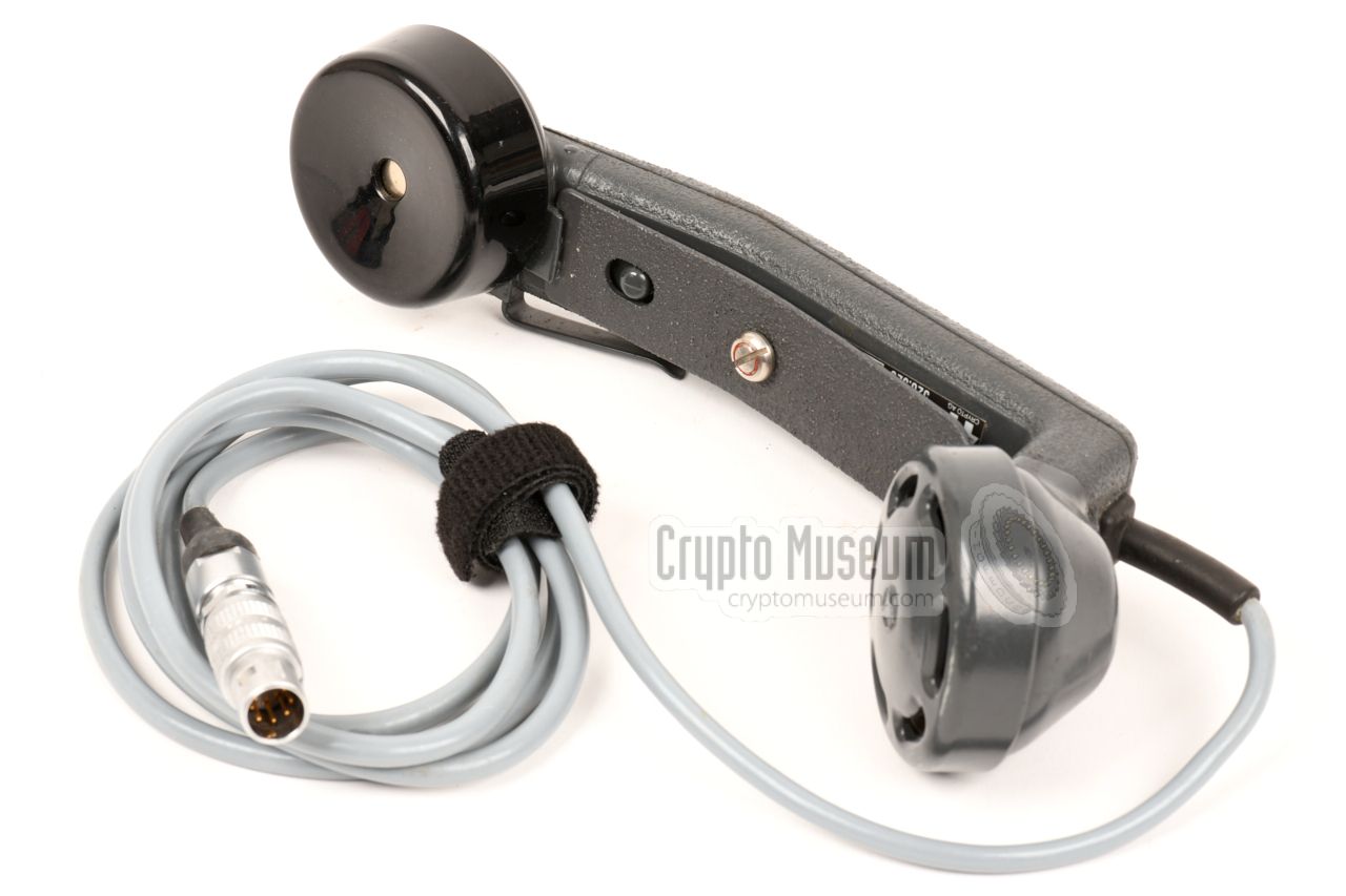
The default input/output device for the HC-235 scrambler is the
Swiss military Microtel handset shown in the image on the right.
It is similar to the ones that are used on other Swiss military
equipment, such as field telephone sets.
The handset consists of a metal grip, with a mouthpiece (microphone)
and a displaced earpiece (speaker). A push-to-talk (PTT)
switch is mounted in the grip. The handset has a straight cable
(as shown here) or a coiled one.
|
|
|
When using the CRM-008 over an analogue (PSTN) telephone line,
this special crypto phone had to be used instead of a standard one.
The special phone is in fact a standard telephone set that is
modified for crypto use. It has extra switches and and an indicator
to show that the connection is secure. The phone should be connected
to the telephone line breakout box.
|
|
|
|
|
Radio adapter (1)
ARA-100-001
|
|
|
This junction box was used for connecting the CRM-008 to any type
of (external) two-way radio set, such as military HF communications
transceiver. It is fitted with an 10-pin LEMO
plug that fits the data socket on the front panel.
The box has a built-in speaker with volume control – for monitoring –
and has fixed wiring at the rear for connection of the input and
output devices (transmitter and receiver).
|
|
|
|
|
Radio adapter (2)
ARA-100-002
|
|
|
Instead of the speaker unit shown above, it was also possible to
use the radio interface box shown in the image on the right.
It connects to the same 10-pin LEMO socket on the front panel,
marked 'DATA', but does not have an internal speaker.
The box shown in the image has fixed wiring from the transmitter
and receiver, and a socket for connected of a pair of headphones.
In practice, the headphones socket was sometimes replaced by a
volume knob.
|
|
|
|
|
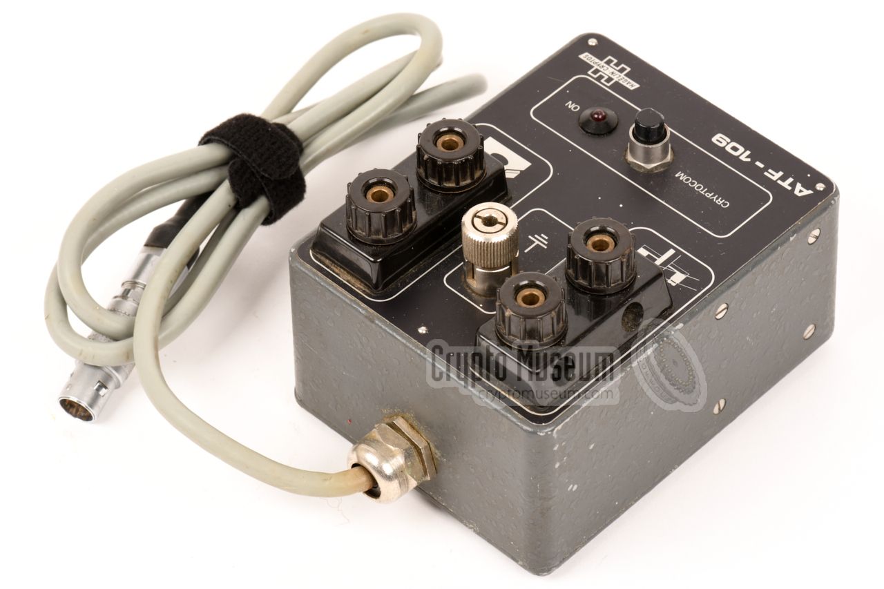
Telephone adapter
ATF-109
|
|
|
When using the CRM-008 over a regular analogue PSTN telephone line,
the breakout box on the right was generally used. It has banana
socket for connection to a 2-wire line, plus two banana sockets
for connection of the (regular) telephone set.
The breakout box has a fixed cable with a 10-pin LEMO plug at the end,
that fits the DATA socket on the front panel.
|
|
|
|
|
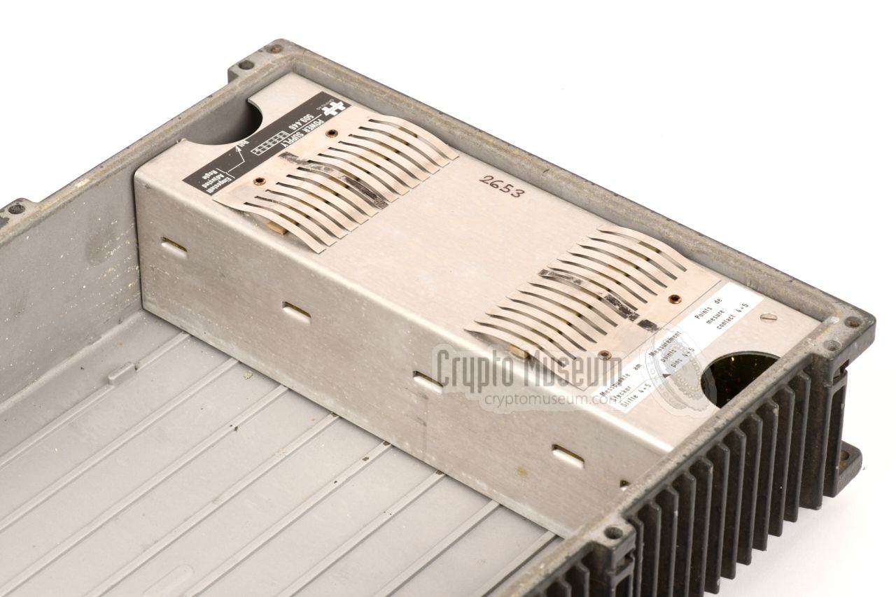
Power supply unit
PSM-106
|
|
|
The CRM-008 has a wide power input range from 10 to 30V DC.
In a mobile environment, it was usually powered by the
battery of a car (12V) or a truck (24V).
In a fixed setup, e.g. in an office, it could be powered from the
mains, by using an external power supply unit (PSU), such as the
one shown in the image on the right.
|
|
|
Although the CRM-008 operates on analogue (speech) signals, the
internal processing takes place in the digital domain. After
the signal has been processed, it is converted back into an
analogue signal, so that it can be transmitted over a standard
narrow-band (radio) channnel.
The audio signal is first split into two frequency bands
by means of filters A and B. These filters have a cut-off frequency of
1600 Hz with 5 selectable offsets (-300, -150, 0, 150 or 300 Hz).
The two streams are then digitized and kept in separate buffers
where they are processed further. In between the two frequency bands
is a 1600 Hz pilot tone (P) that controls the synchronization between transmitter
and receiver and also controls the built-in Automatic Gain Control (AGC).
In the buffers, each segment of 320 ms is divided into 8 individual
sections of 40 ms each. The 8 sections of the A-channel are then
mixed with the 8 sections of the B-channel in a pseudo-random order
that changes every 320 ms, under control of the built-in digital key
generator.
Finally, the scrambled data sections are converted back to analogue
signals in two D-A converters and mixed together in filters C and D.
As the output signal still contains the characteristics of regular
speech, it can be transmitted over narrow-band channels
without any problems.
At the time (1970s),
frequency/time domain scrambling (F/T)
was considered safe against professional eavesdropping.
Using modern correlation techniques however, it is easily defeated
without the need to recover the actual key.
F/T scrambling should now be regarded as extremely unsecure.
|
|
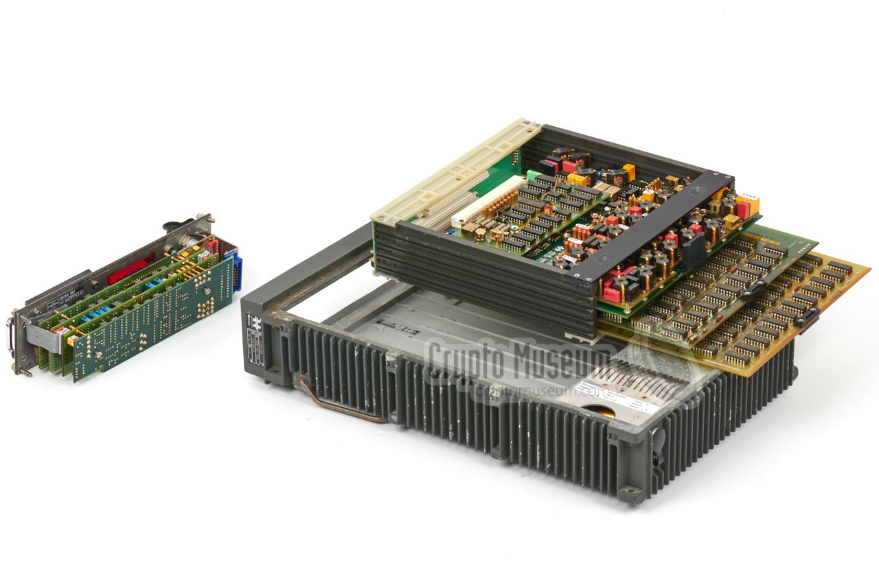
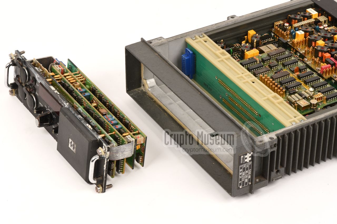
The interior of the CRM-008 (HC-235) can be accessed by releasing the
eight large bolts (marked with a red circle) at the top of the device,
and taking the top lid off.
The device consists of three building blocks:
(1) front panel, (2) processor assembly, and (3) a DC/DC power converter
(PSU).
|
The front panel unit is a separate assembly that consists of four
printed circuit boards (PCBs), that
are mounted to the rear side of the front panel. The keypad, the LED
display and the sockets are all integrated with this section.
The front panel is connected to the processor unit, via a blue 25-pin
connector at the rear left. It can be removed by releasing the four
red-marked bolts in the corners of the front panel, and pulling it out
using the metal grips at the outer edges.
The image on the right shows the front panel assembly, removed from
the case.
|
|
|
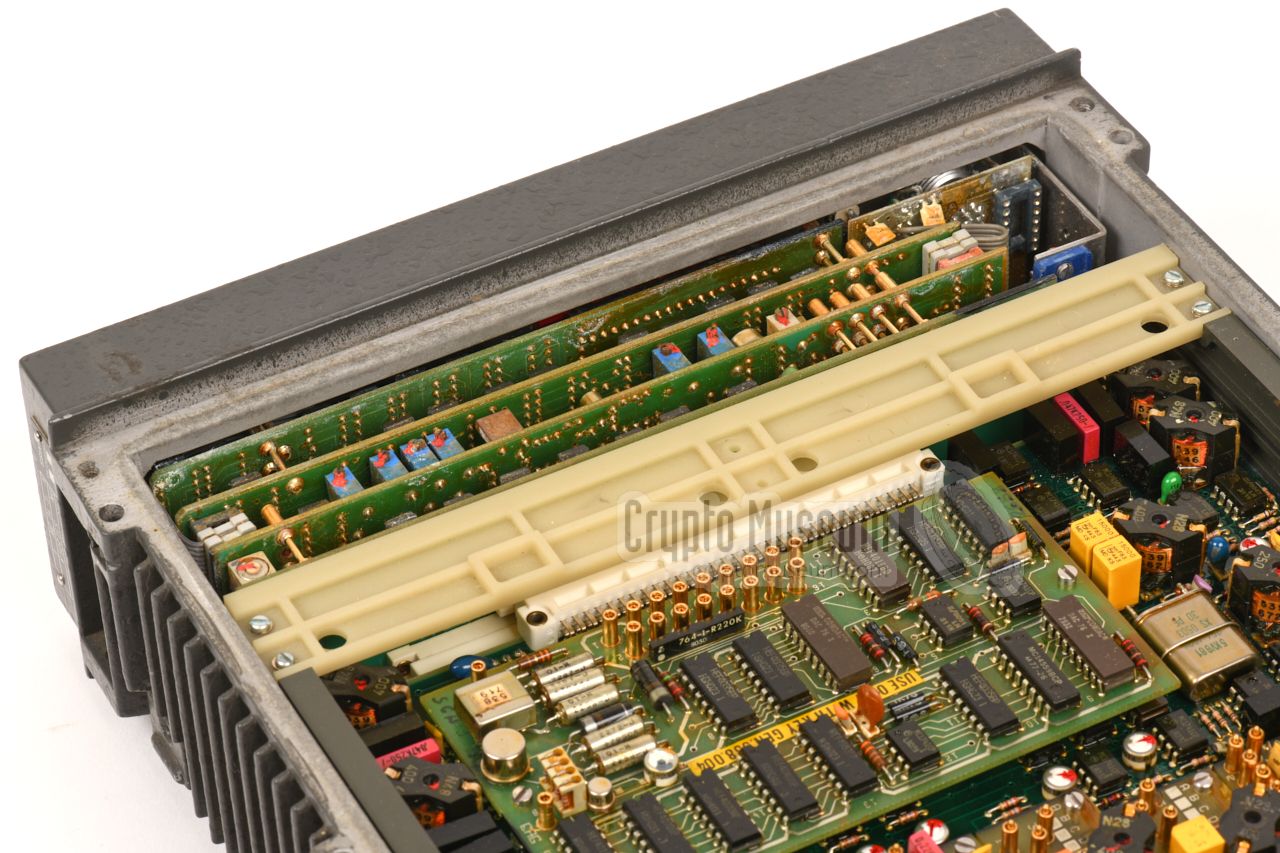
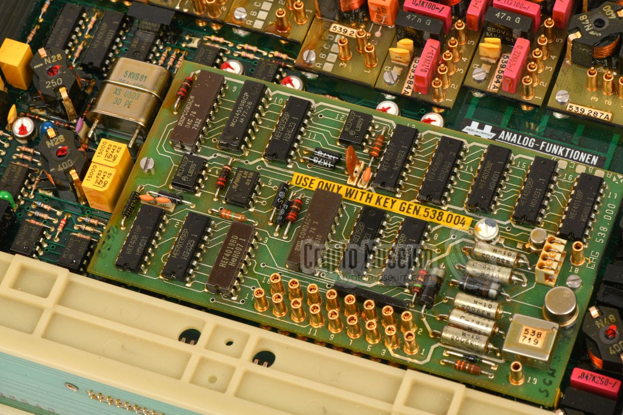
The processor unit
consists of a slotted plastic frame, with a backplane
PCB at the front.
Three large PCBs are inserted into the frame from the
rear and are connected to the backplane. A forth (smaller) PCB is fitted
on top of the upper board.
At the top of the stack is the
audio board.
In holds the input and output
amplifier and several
pluggable high-quality audio filters.
A digitiser (A/D converter)
it mounted on top of the audio board as a plug-in unit.
It is responsible for the conversion of speech into digital
data, and forms a matched pair with the key generator board.
|
|
|
|
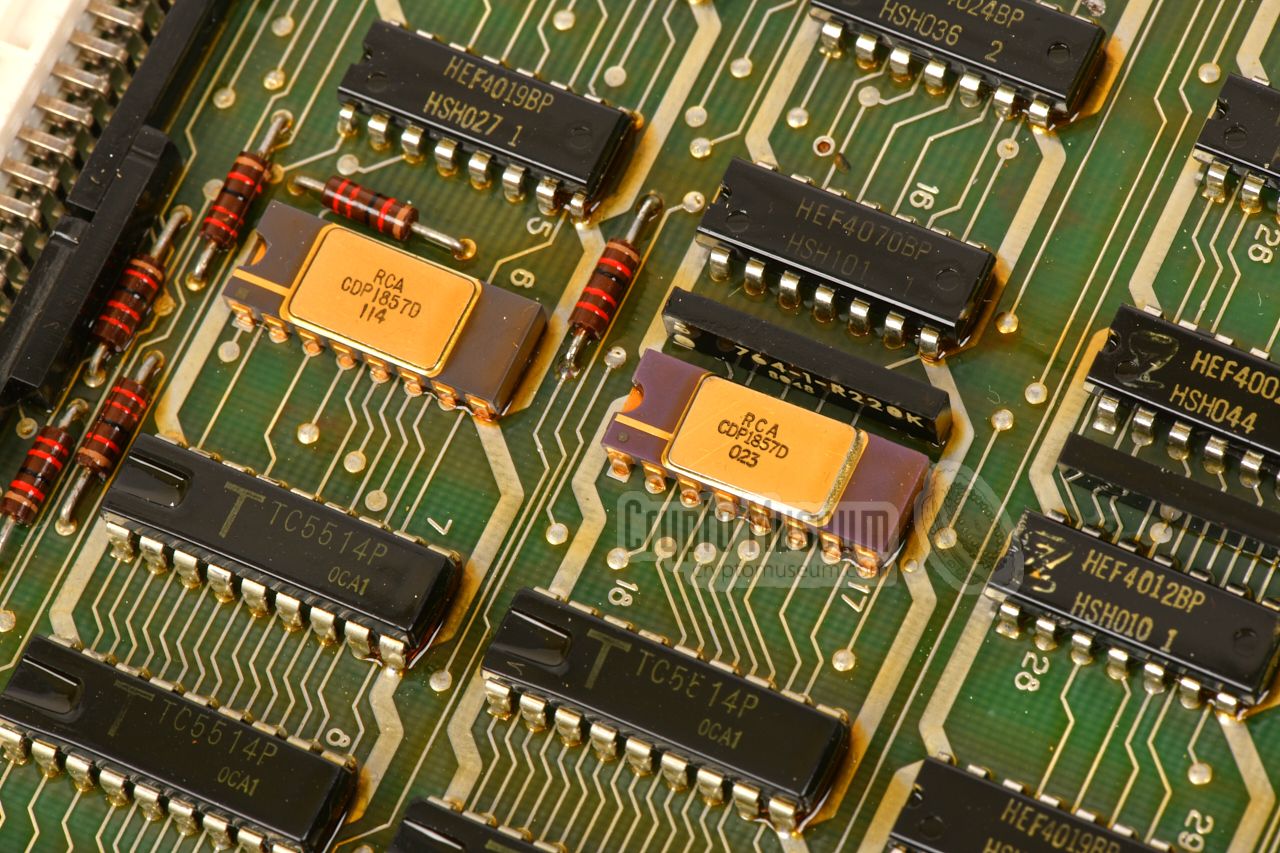
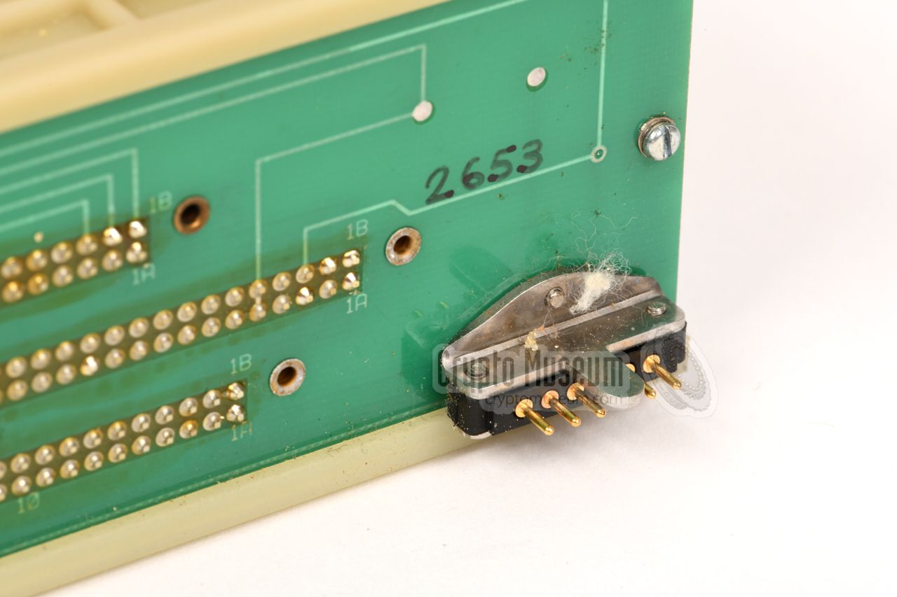
The key generator
is at the centre of the PCB stack. It consists of
a pseudo-random generator that is based on hard-wired discrete
linear feedback shift registers (LFSRs), of which the initial state,
or initialisation vector (IV),
is determined by the cryptographic key
entered by the user.
|
The key generator board also holds the volatile memory (SRAM) in
which the user-entered key is stored. It is retained by means of a
rechargeable NiCd battery that is also mounted on the board.
It takes ~20 hours to fully charge this battery. 1
A fully charged NiCd battery should be able to preserve the key for
more than one month [1].
At the bottom of the stack is the control board, that acts as a
system-wide supervisor. It holds the memory in which the digitised
audio from the two frequency domains (A and B) is stored, and swaps it
under control of the key generator.
|
|
|
|
The control board is also responsible for handling the user input and
output from the front panel unit, and ensures that a new message key
is generated each time a transmission is started — i.e. when the user
presses the Push-To-Talk switch (PTT) that is located in the grip of
the handset.
|
-
Assuming that the NiCd battery is still healty.
|
|
It appears that the first devices were sold in the late 1960s or the
early 1970s, and that they were designated CRM-008-001 (002) and CRM-008-007.
It is likely that the model number was later changed to HC-230 for the
desktop version, and HC-235 for the ruggedised military version.
So far, the following model numbers, part numbers and serial numbers
have been observed:
|
| Model | P/N | S/N | Date 1 | Remark |
|
|
| CRM-008-001 | ST 528 879 | 5 535 375 | ? | Ebay |
| CRM-008-001 | ST 529 537 | 5 535 387 | 1981 | Argentine Navy 2 |
| CRM-008-002 | 538 830A | 5 535 594 | ? | Argentine Navy 2 |
| HC-235 | 530 275A | 5 535 479 | 1977 | Argentine Navy 2 |
| HC-235 | 530 275A | 5 535 490 | 1977 | Argentine Navy 2 |
| HC-235 | 530 275A | 5 535 496 | 1977 | Argentine Navy 2 |
|
-
Estimated manufacturing date, based on date codes on the components.
-
Serial number recorded by Crypto Museum.
|
|
At the rear of the device is a 4-pin LEMO socket for connection of a
DC power source between 10 and 30V. The diagram below shows the layout
of the socket when looking into the contacts.
The upper two contacts go to the (-) terminal of the battery,
whilst the lower two go to the (+).
|
- 0V
- 0V
- +10 to 30V
- +10 to 30V
|
|
|
At the top left of the front panel
is a 10-pin LEMO socket marked DATA.
This socket is used for the connection to the outside world (telephone line,
radio, etc.). The diagram below shows the layout of the socket when looking
into the contacts.
|
AFI AF input GND Ground (line) DXO Output to line AFO AF output SYNC Sync OK (open collector output) PTT Push-to-talk (input/output) /C Select Crypto mode (input) DXI Input from line -6V -6V power output +6V +6V power output
|
|
|
At the bottom left of the front panel
is an 8-pin LEMO socket for connection of a
handset, headset or a similar microphone/speaker
arrangement. The diagram below shows the layout of this socket
when looking into the contacts.
|
SPK Speaker (1) GND Speaker (2) MIC1 Microphone (1) - unused MIC2 Microphone (2) PTT Push-to-talk (1) GND Push-to-talk (2) 1 - unused
|
|
-
In some handsets, the second contact of the push-to-talk switch (PTT)
is wired to pin 2 rather than pin 7. These pins are functionally identical,
as they are both wired to Ground (GND).
|
Local 2-wire 600Ω Line 2-wire 600 Ω Power 110/220V AC 50/60 Hz, 9W (switch selectable) Temperature -25°C to +55°C (storage: +40°C to +80°C) Dimensions 340 x 255 x 140 mm Weight 7.1 kg
|
Local Mic: 2-wire ≥ 240Ω, Aux-in ≥ 10kΩ, Ear: 200Ω, Aux-out 600Ω Line DX in: ≥ 12kΩ, DX out: 600Ω Synchr. Continuously, pilot tone 1600 Hz ± 33 Hz Temperature -25°C to +55°C (storage: +40°C to +80°C) Dimensions 375 x 240 x 80 mm Weight 5.7 kg
|
Synchr. Continuously, pilot tone 1600 Hz ± 33 Hz Sync delay Typically 2 sec (max: 5.5 sec) Delay 0.8 sec (after change-over) AFC ± 100 Hz Adj. ref. ±75 Hz, ±150 Hz Key space 1032 SRAM With iternal NiCd battery to retain key
|
- VC-008
- CRM-008
- HC-230
- HC-235
- CRYPTOCOM
|
Please help us to expand this page,
by providing additional information.
We are still looking for the full (extended) operating instructions
and for technical documentation of the CRM-008,
HC-230 and/or HC-235, such as circuit diagrams etc.
We are also looking forward to hearing from people who have worked
with these devices in the field.
➤ Contact Crypto Museum
|
-
Document kindly provided by collector Immo Hahn [2].
|
|
|
|
Any links shown in red are currently unavailable.
If you like the information on this website, why not make a donation?
© Crypto Museum. Created: Monday 24 August 2009. Last changed: Sunday, 14 January 2024 - 17:39 CET.
|
|

|
|
|
|


![UK soldiers during the Falklands War. Photograph via History Collection on Pinterest[4].](img/falklands_large.jpg)