|
|
|
|
|

|
|
← UVK-20 CIA NRP Easy Chair UVK-153 →
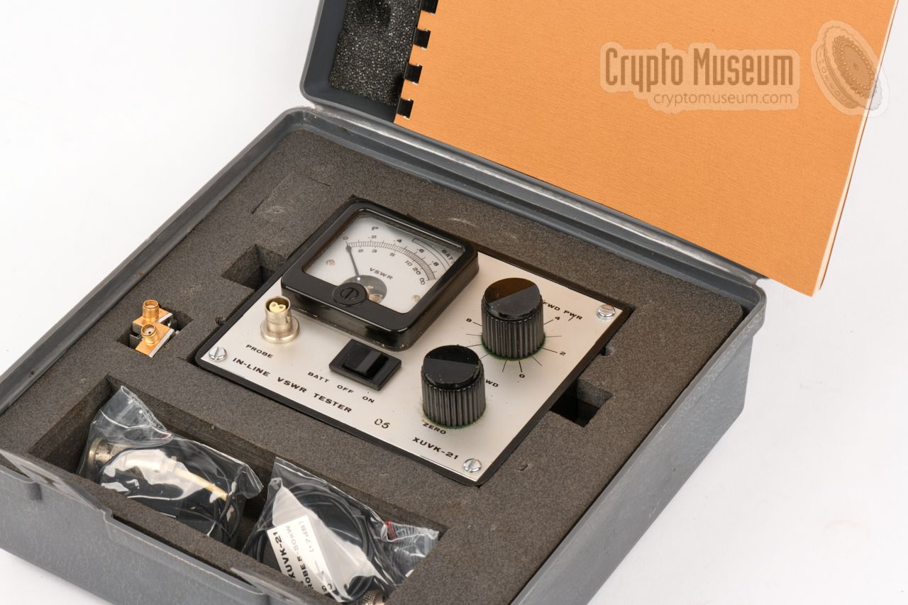
The device was made especially for measuring the quality of the RF match
between an installed
surveillance transmitter (bug)
and a generally
unpredictable antenna system, operating in the CIA's favorite 380 MHz band.
It can also measure the actual RF output power of the transmitter.
At the left, just below the meter,
is a BNC-twin socket to which the
probe is connected. The unit was supplied with a collection of
fully passive sampling line modules,
that can be inserted into the
transmission line, as close to the transmitter as possible,
with the probe
placed on top of it.
|
|
|
|
Development of the UVK-21 started in the mid-1970s, alongside the
UVK-20 —
a single-ended VSWR meter with built-in RF source. The first prototype was
presented to the CIA in 1978 [A]
and was thoroughly evaluated [B] before it was
taken into production in 1980 [C].
The CIA used it to validate the
performance of bugs and the accompanying antennas
under simulated conditions.
|
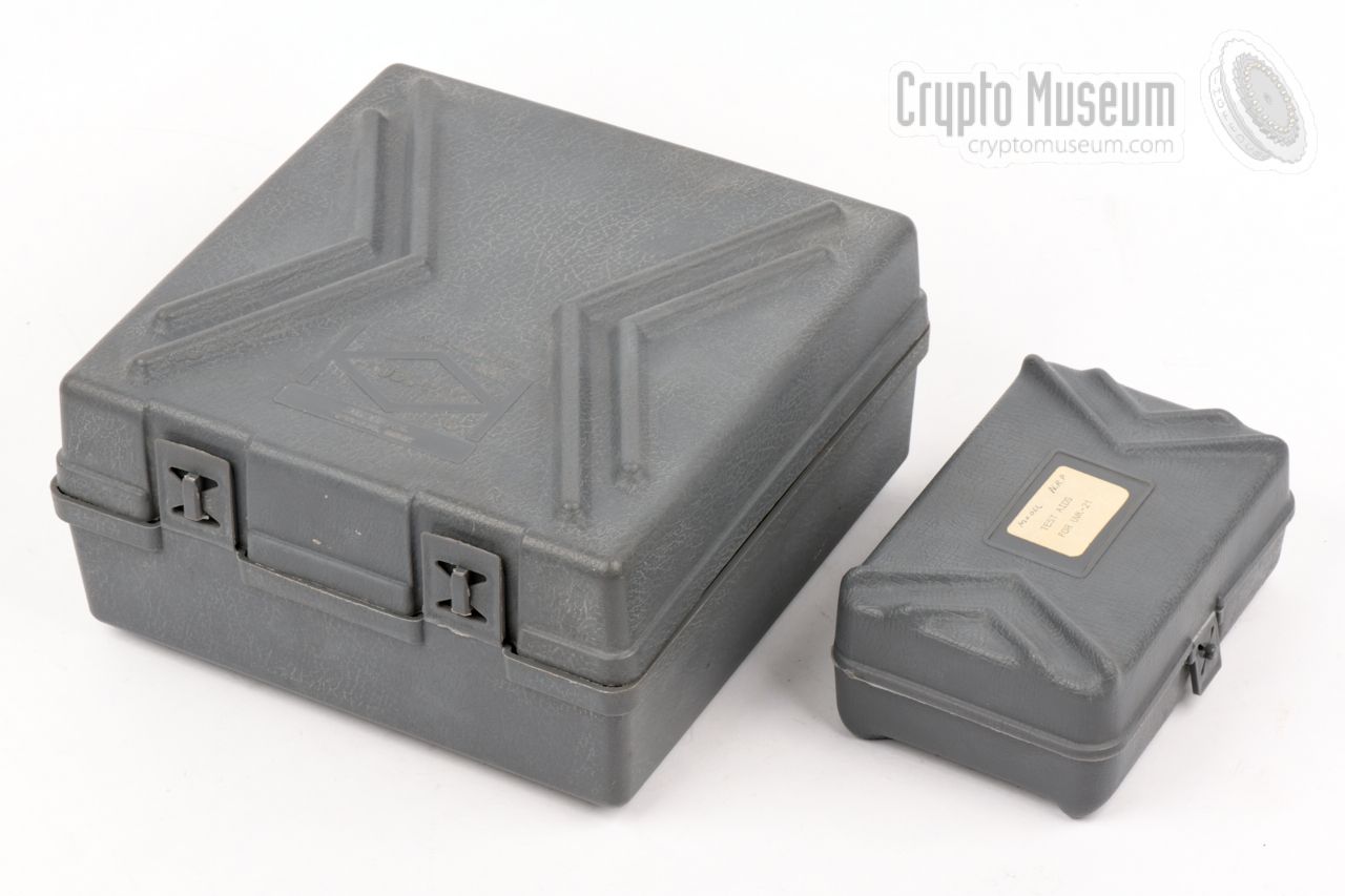
The photograph below gives an overview of the items that were present
in the UVK-21 kit. The largest part is the actual indicator unit. It is
powered by a single 9V block battery that is installed behind a lid in
the bottom left corner. Depending on the output power of the
bug under test, the appropriate probe
(1-10 or 5-50 mW) should be connected to the
BNC-twin socket at the left.
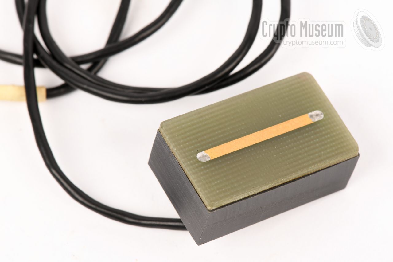
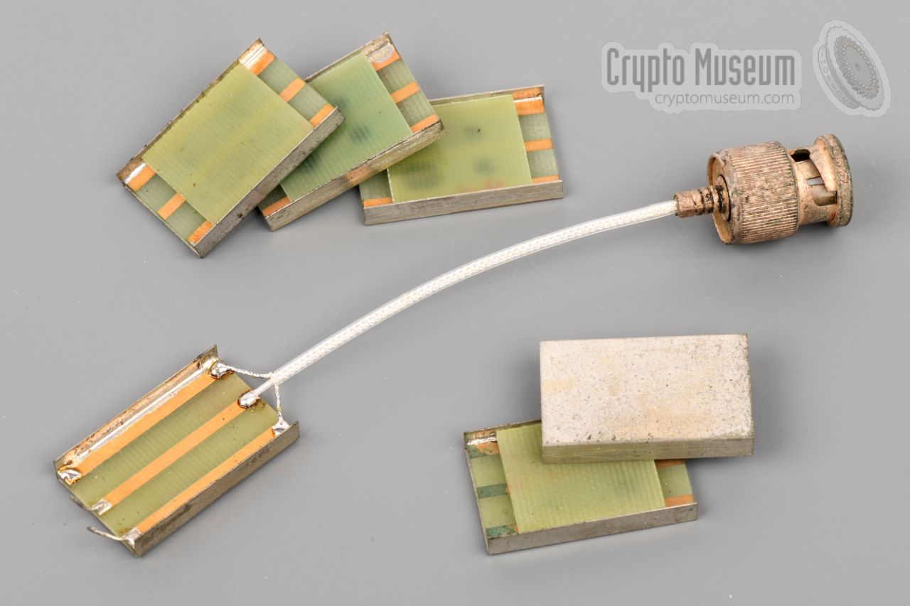
The unit was supplied with 10
universal sampling line modules, one of which
had to be inserted (soldered) between the transmitter and its antenna,
as close to the output of the transmitter as possible. This is considered
a disposable part, as it was left in place during the operational
life of the bug. For measurements in a laboratory,
sampling units with SMA sockets
were also available.
|
The diagram below shows how the UVK-21 is used. At the top left is the
transmitter under test (i.e. the bug), powered by its own local
battery or PSU. A
(disposable) sampling line module (SLM)
is now soldered
directly to the antenna output of the transmitter, preferably with a
ground wire at either side. At the other end of the sampling line module – which
is actually an open piece of 50Ω transmission line – the antenna
is connected. This can be a piece of wire of arbitrary length, or
a proper antenna, like a Sleevex,
in which case a coaxial line should be
soldered to the SLM output.
The probe is now placed in the cradle
of the SLM, with the arrow pointing
from the transmitter to the antenna. The transmitter is now activated and
the meter is adjusted for maximum reading.
Next, the probe is reversed, so that the arrow points from the
antenna to the transmitter. The meter now shows the amount of energy that
is reflected from the antenna, directly in VSWR.
A mid-scale reading (VSWR = 6) means a loss of 50% and is considered a bad match. Likewise, anything below a 10% reading (VSWR ≤ 2) is
considered satisfactory. Although the SLM introduces an
insertion loss of 0.25 dB, this will outweight the gain of a properly
matched configuration.
|
Frequency 240 - 400 MHz Power 6.5 to 10 V (typically a 9V block battery) Current ≤ 4 mA Connection BNC-twin Impedance 50Ω Probes 2 (see below) Sampling Module 30 x 19 x 4.5 mm Loss ≤ 0.25 dB Dimensions 127 x 108 x 67 mm Weight 550 grams
|
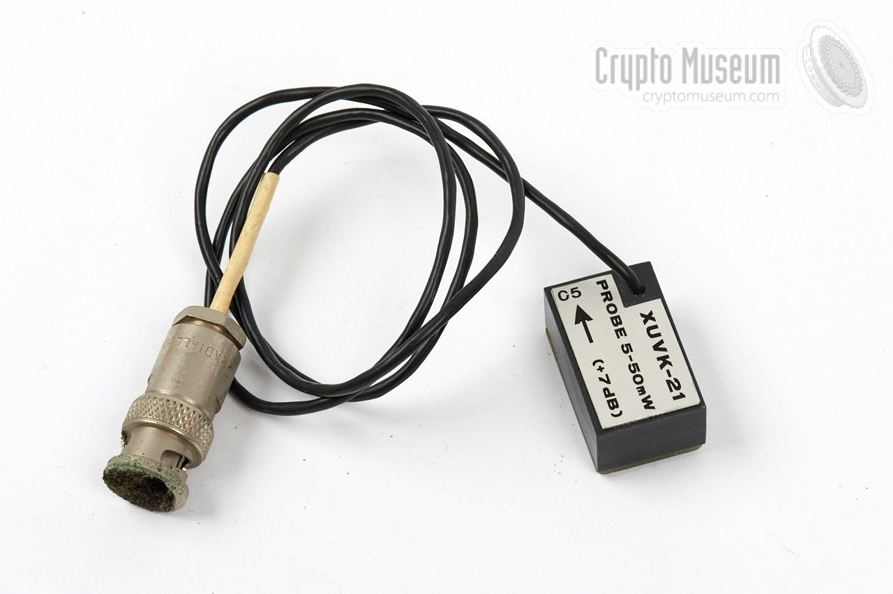
1-10 mW low-power probe 5-50 mW medium power probe
|
- 1 x Indicator (the actual UVK-21 unit)
- 1 x Probe module 1-10 mW
- 1 x Probe module 5-50 mW
- 10 x Sampling module
- 1 x Final test data sheet
- 1 x Operator's manual
|
- UVK-21, prototype in-line VSWR tester
CM-302542/B. NRP, May 1978.
- XUVK-21 Evaluation
CIA, date unknown. Preliminary draft.
- UVK-21 Inline VSWR Tester, Technical Manual
CM-302542/K. NRP, March 1980.
|
|
|
|
Any links shown in red are currently unavailable.
If you like the information on this website, why not make a donation?
© Crypto Museum. Created: Saturday 12 October 2019. Last changed: Sunday, 13 October 2019 - 10:19 CET.
|
 |

|
|
|