|
|
|
|
|

|
Portable short-wave receiver
XCR-30 was a portable transistorised
short-wave (SW) receiver,
introduced in 1969 by Barlow-Wadley in New Germany (South Africa).
The device has an extremely wide frequency span of 500 kHz to 30 MHz –
divided over 30 linear 1 MHz segments –
which it owes to the so-called Wadley Loop, an invention of Dr. Trevor Wadley
that was also used in Racal
receivers like the RA-17 [3].
|
Although the receiver has the appearance of a cheap Japanese portable
radio of the 1970s, it is in fact a well-designed, well-built device in
a shielded strong (partly die-cast) metal case.
In the 1970s, the XCR-30 was a highly desired receiver amongst radio amateurs,
many of whom couldn't afford the relatively high initial price of US$ 269.
Over the years, several versions and variants of the receiver appeared
on the market, such as one with a complementary FM broadcast receiver
mounted at the top,
and a rather rare one in a dark green (military-looking) enclosure.
|
|
|
The receiver is suitable for the reception of AM, LSB and USB narrowband
signals. The FM version – featured here – is also suitable for the reception of wideband
signals in the 87.5 to 101 MHz range.
Although its tuning principle was revolutionary at the time of the introduction,
it lost its popularity when the Phased Locked Loop (PLL) and the
Frequency Synthesizer were introduced.
Due to the unobtrusive appearance of the radio, its wide frequency coverage,
and the fact that it could be purchased from radio stores in the USA and in
Europe without attracting any attention, the XCR-30 was also used during the
Cold War by
intelligence services
from both sides of the Iron Curtain,
for example for the reception of messages via the
One-Way Voice Link (OWVL). 1
The radio was first introduced in 1969 2 for a price of US$ 269
and was in production until 1981.
In the UK, it was distributed by the Radio Shack for GBP 146,
with the optional TR-801 FM tuner separately available for GBP 25 [6].
In Germany, the XCR-30 Mark 2 was sold in 1974 for DM 740.
|
 |
-
Also known as Numbers Stations.
-
Initial introduction in South Africa. Some countries followed later.
|
The diagram below provides a quick overview of the features of the
Barlow-Wadley XCR-30 Mk2, which – in this case – has the optional TR-801
FM broadcast band receiver fitted at the top, which raises the
frequency table
— collapsed here — and the carrying handle by several centimetres.
The actual shortwave receiver – the lower part – has two tuning knobs
and two frequency scales. At the left is the setting for the MHz,
whilst the setting for the kHz is at the right. This way the radio
provides 30 linear segements of 1 MHz each, with a tuning accuracy
of approx. 5 kHz. Fine tuning is possible with the small knob below
the S-meter, whilst for the reception of SSB (LSB or USB)
a separate clarifier control is present. The desired MODE is selected
at the bottom right.
|
- XCR-30
This is the original model, introduced in 1969, which is built around 18
transistors. It is likely that this version was never sold in Europe.
It was succeeded in 1973 by the XCR-30 Mark 2, but the differences between
the two versions are unclear.
- XCR-30 Mark 2
This model was probably introduced in 1970.
It is nearly identical to the original version, but may have been improved,
although it is currently unclear what the improvements are.
The XCR-30 receiver featured on this page, is of this type.
Around June 1974, the circuit was further improved with
an audio amplifier built around a TAA611 integrated circuit (IC)
and a new design for the 1 MHz harmonic generator.
The improved version contains one IC and 14 transistors,
some of which are slightly different from the original ones.
- TR-801
Optional tuner for the 87.5 to 101 MHz FM broadcast band, that can be mounted
on top of an existing XCR-30 Mark 2 receiver.
It was available as an add-on kit for GBP 25 (UK, 1975) [6].
It is present on the XCR-30 receiver featured here.
- XCR-30 FM Mark II
This model is largely identical to the XCR-30 Mark 2, but comes with the
TR-801 FM broadcast receiver (87.5 to 101 MHz) already installed.
The TR-801 is completely separate from the rest of the radio and
was also available separately as the TR-801 add on (see above) [6].
This model was available in Germany in 1974 for a price of DM 740.
|
Below is the block diagram of the XCR-30 radio. At the top left is
the antenna input circuit, which comprises a novel
pre-selector with
hand-operated permeability tuning, an RF pre-amplifier and a low-pass filter.
This signal is then mixed (X1) with the free-running
45.5 - 75.5 MHz output of the MHz-VFO,
which forms one half of the Wadley Loop,
resulting in an IF1 of 44.5 to 45.5 MHz.
The same 45.5 - 75.5 MHz signal from the MHz-VFO is mixed (X2) in the other
half of the Wadley Loop, with the output of an harmonic generator that produces
a series of signals between 3 and 33 MHz at 1 MHz intervals. Only the 42.5 MHz
product of X2 is used,
and is mixed (X3) with the IF1 signal from the first half of the Wadley Loop,
resulting in a 1 MHz wide 2 - 3 MHz IF2 signal.
The rest of the circuit is bascially a regular heterodyne receiver.
The 2-3 MHz IF-signal is mixed in X4 with the output of the free-running
kHz-VFO, resulting in a 455 kHz IF3-signal,
which is fed to an AM-detector and amplified to speaker level.
For the reception of Single Side Band (SSB) signals
(LSB, USB) and CW (morse),
an adjustable Beat Frequency Oscillator (BFO) can be enabled.
This design is also known as a triple-conversion receiver with IF frequencies
at 45 MHz, 2.5 MHz and 455 kHz.
Note that this circuit has an
inherent drift compensation:
if the MHz-VFO drifts, the drift equally affects the output of
X1 and X2, which is cancelled out in X3.
As a result, the quality of the receiver is only determined by the
stability and accuracy of the 1 MHz crystal oscillator.
|
|
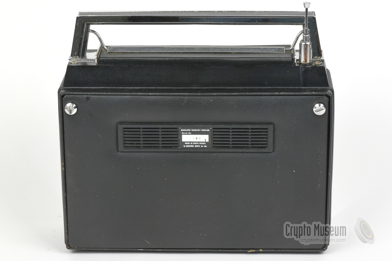
The interior of the XCR-30 can be accessed by loosening the two large
bolts in upper corners of the rear panel,
after which the hinged rear panel can be lowered, 1 as shown in the
image above. A plastic battery holder for six 1.5V D-size battery
cells, is mounted to the inside of this panel.
|
Inside the metal case is a large printed circuit board (PCB)
with two large cut-outs, one for the speaker and one for the cylindrical
tuning scales. The PCB holds all circuits, except for the
1 MHz harmonics generator,
which is mounted at the other side
of the PCB, behind the front panel.
The image on the right shows an early version of the XCR-30 Mk2, in
which the output stage of the AF amplifier is built around two
Germanium transistors.
In June 1974 they were replaced by a TAA 611 integrated circuit (IC).
At the same time the harmonic oscillator
was altered (see below).
|
|
|
The upper half of the PCB holds two variable frequency oscillators
(VFOs). At the right is the main VFO that is used to select the MHz,
resulting in an IF1 frequency around 45 MHz. This signal is mixed with
the 42.5 MHz from the harmonic generator, resulting in an IF2
frequency around 2.5 MHz. This signal is then mixed with the
2.455-3.455 MHz signal from the kHz VFO, resulting in an IF3
frequency of 455 kHz, which is then passed to the detector and amplified
to speaker level.
At the top right is the pre-selector
which is further described below.
It is adjusted in tandem with the MHz
VFO. Although the sensitivity of the receiver is very good, the
dynamic range is not. The pre-selector can not prevent overloading
by signals in the same 1 MHz segment, and neither can the Automatic Gain Control
(AGC), which only affects the IF3 stage and not the RF pre-amplifier.
|
-
The rear panel can be removed completely, by opening it by just 5 mm
and then pulling it upwards.
|
The receiver has a beautifully constructed pre-selection filter that is
located between the antenna input circuit and the RF pre-amplifier. It
consist of a 1st order parallel tuned circuit, of which the capacitor (C) is
tuned in tandem with the MHz-VFO. The inductor (L) has a ferrite
core that moves with the ANTENNA TRIM knob at the front panel. In fact,
the inductor consists of three separate windings, one for each frequency range:
(1) 0.5 - 2 MHz, (2) 2 - 8 MHz and (3) 8 - 30 MHz.
The image above shows the construction. At the bottom centre is the
ANTENNA TRIM knob, which operates a cam-wheel. The cam has two sloped edges,
each of which can engange a microswitch. Depending on the position (angle)
of the TRIM knob, either or both microswitches are activated.
|
The harmonic generator
is implemented as a separate PCB, which is mounted
to the solder side
of the main PCB. It can only be accessed
from the front of the device, for which the knobs and the front panel
have to be removed.
In the original design, it consisted
of a 1 MHz crystal oscillator, of which the output was filtered and applied
to an AA112 diode (which causes the harmonics to be generated)
and then passed
through a 4-stage PI-filter, before applying it to mixer X2.
Apparently this design caused problems in some receivers,
as it was dropped around June 1974 [B].
In the improved design, a small transformer with just 3 windings is used as
the non-linear element, by applying a 1 MHz signal with a level that is
high enough to saturate its ferrite core. At the same time, the 4-stage
filter was replaced by a single-stage long ferrite bead (ferrox core).
|
|
When we received the Barlow-Wadley XCR-30 featured here, it was not
in good shape. Apart from being very dirty, its interior
showed severe corrosion
– especially at the bottom panel –
which had clearly been caused by leaking batteries.
Apparently it had been stored
for a long time, without removing the old batteries.
It demonstrates that batteries are the biggest enemy of a collector.
|
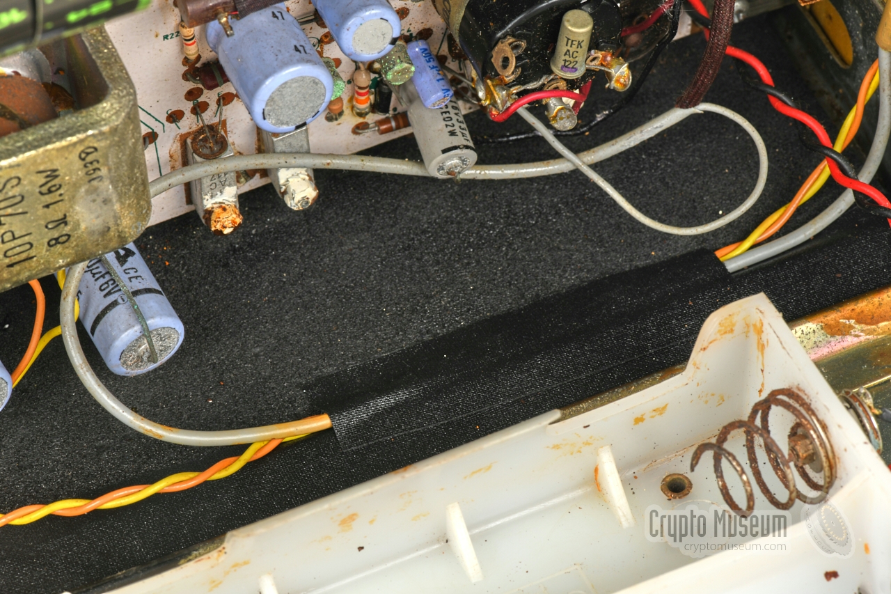
After removing the most obvious corrosion and cleaning the
battery holder, the bottom panel was treated with Owatrol® ,
a substance that prevents further corrosion.
The bottom panel was then covered with a thin piece of
neoprene foam,
after which the
wiring was taped in place.
The image on the right shows the bottom panel of the radio
and the battery holder, before the restoration. Although the
battery holder is now functional again, it is better to
demonstrate the radio in the future by means of an external
power supply unit (PSU) or a mains AC adapter.
|
|
|
|
After the initial restoration was completed, it was time to power the
radio up. Although it received a local radio station
in the FM broadcast band (87-106 MHz), the sound was heavily distorted.
As the shortwave receiver exhibited the same problem, the root cause had
to be in the AF amplifier.
|
A closer inpection of the AC175 (TR15) and the AC117 (TR16) in the final
stage of the amplifier, revealed that the legs of these transistors were
severely corroded and were partially missing,
again caused by leaking batteries. It was decided to replace them by
AC187/AC188 respectively.
As the caps and the legs of the two driver stages - BC108 (TR13) and
BC262 (TR14) – were also heavily corroded, it was decided to replace them
by a BC547 and BC557 respectively. This turned out to be a good decision,
as the legs fell apart the moment TR13 and TR14 were desoldered.
|
|
|
|
As the front panel had to be removed in order to replace the transistors,
it was decided to replace all electrolytic capacitors at the same time.
They have a tendency to lose their capacity over time, and some of them
showed signs of leakage and corrosion.
The image above shows the result.
|
Further testing revealed an intermittent problem with the pre-scaler.
When turning the ANTENNA TRIM knob, two switches at the circumference
of a cam-wheel, select one of the three available tuning ranges
(see above).
Due to slack on the axle and wear on the tips of the microswithces,
the switches sometimes didn't latch properly, resulting in the
selection of the wrong range.
The problem was solved by re-adjusting the microswitches and
placing them ~ 1 mm closer to the cam-wheel so that they were no longer missed
when turning the ANTENNA TRIM knob.
|
|
|
|
Furthermore, the tips of the switches – that had been flattened by wear –
were rounded off again by means of a dental mill, to avoid excessive shear
forces when catching the ramp of the cam-wheel. The pre-selector now
correctly selects the desired frequency range again, which greatly
improves the sensitivity of the receiver. In a final test we were able
to receive radio amateurs around 3.5 and 7 MHz, and broadcast stations
on 7.2 and 7.4 MHz and in several other bands.
|
|
So far, the following restoration work has been carried out:
|
- Exterior cleaned thorougly
- Exterior paint and artificial leather restored
- Interior thoroughly cleaned
- Corrosion from leaking batteries removed
- Bottom plate restored and treated with Owatrol®
- Frequency table restored
- Transistors TR13, TR14, TR15 and TR16 replaced
- All electrolytic capacitors replaced
- Microswitces on the pre-selector cam-wheel re-adjusted
- Speaker gasket replaced
|
| ID | Type | Polarity | Replacement | Remark |
|
|
| TR13 | BC108 | NPN | BC547 | Note the odd placement of the pads |
| TR14 | BC262 | PNP | BC557 | Note the odd placement of the pads |
| TR15 | AC175 | NPN | AC187, AC127 | |
| TR16 | AC117 | PNP | AC188, AC128 | |
|
The XCR-30 receiver was developed by Dr. T.K. Wadley, who had previously
worked for the South African Council for Scientific and Industrial Research
(CSIR) and had developed receivers for Racal
in the UK.
He is the inventor of the so-called Wadley Loop [7], which was also used in
expensive professional contemporary Racal receivers, and in other
equipment of the South African and British governments.
The Wadley-Loop is still used today in the design of spectrum analyzers [5].
The XCR-30 was manufactured by the Barlows Group in South
Africa — who also built domestic Sony and Matsushita (Panasonic)
equipment under licence —
at the Barlows Television Company plant in New Germany (Natal, South Africa).
Upon its introduction (around 1970), the XCR-30 became an instant hit
among radio amateurs all over the world.
Despite the fact that approx. 20,000 units were produced, not many have survived.
And the ones that did survive, are often damaged by leaking batteries.
Nevertheless they occasionally turn up on auction sites like eBay.
|
|
The Wadley Loop was used in the following receivers [8]:
|
- Racal RA-17
- Racal RA-117
- Racal RA-217
- Racal RA-1217
- Racal RA-1218
- General Dynamics R-1051
- Barlow Wadley XCR-30
|
- Drake SSR-1 1
- Yaesu FRG-7 2
- Sommerkamp FRG-7 2
- Sears Communications Receiver 2
- Realistic DX-300
- Lowe SRX-30 1
- Century 21 1
- Standard C-6500 1
|
-
Based on SSR-1 made in Japan.
-
Based on FRG-7 made by Yaesu in Japan.
|
- Barlows Television Company
Division of Barlows Manufacturing Company Limited
29 Shepstone Road
New Germany 3600
South Africa
|
At the left side of the XCR-30 are two sockets:
a 3 mm jack socket for connection of the headphones (bottom) and a
universal power socket for connection of an external 6-12V power source (top).
Note that the negative terminal should be connected to the centre contact,
whilst the positive terminal should be connected to the sleeve. This is
different from most other devices.
|
Type Wadley-Loop (tripple-conversion) Frequency 500 kHz to 30 MHz Clarifier ± 1.5 kHz Accuracy < 5 Khz Mode AM, LSB, USB, CW Sensitivity ≤ 1µV for 50 mW Selectivity 6 kHz (AM), 3 kHz (SSB, CW) IF (1) 45 MHz, (2) 2.5 MHz, (3) 455 kHz Audio 0.4 Watt Response 150 kHz to 3 kHz @ 3dB Image Rejection ≥ 50 dB (≥ 60 dB on fixed images) Antenna Telescopic or external (using antenna and ground terminals) Transistors 18 (from June 1974 onwards: 14 + 1 IC) Power 6 to 12 V DC (typically 9V) Batteries 6 x 1.5V D-size (9V) Current 20 mA (with no audio) Dimensions 292 × 190 × 98 mm Weight 4140 grams Price US$ 267 (USA, 1969) Quantity ~ 20,000
|
|
|
|
Any links shown in red are currently unavailable.
If you like the information on this website, why not make a donation?
© Crypto Museum. Created: Wednesday 18 September 2019. Last changed: Sunday, 11 October 2020 - 21:26 CET.
|
|

|
|
|
|


