|
|
|
|
|

|
|
France Cold War SBO
|
French cold-war spy radio set
|
The radio set is suitable for transmission of CW signals
(morse code)
on the HF frequency bands between 2.9 and 22.9 MHz, and the reception of
both CW (A1, A2) and AM (A3, phone) signals.
The modular system consists of 4 basic building blocks that are held
together by two mounting frames, which allows it to be carried and tilted.
The unit can be powered from virtually any AC mains voltage in the world, or
from a 6V DC source such as the battery of a car.
The modules can also be combined in other ways, e.g. to form a stand-alone
receiver and/or a battery charger.
|
|
|
|
The TR-TG-2A was introduced in 1965 and was manufactured by Lagier & Cie
(a.k.a. Electronique Lagier SA) in Marseille (France).
It was supplied to the Army in a green padded canvas bag,
or – in case of the intelligence services – in an unobtrusive exectutive-style
briefcase or travel suitcase.
The radio set was succeeded in 1972 / 1973 by the
TR-TG-2B,
which was manufactured by SEFT. The latter came with a
burst transmitter that could
send messages at a speed of 300 baud [4].
|
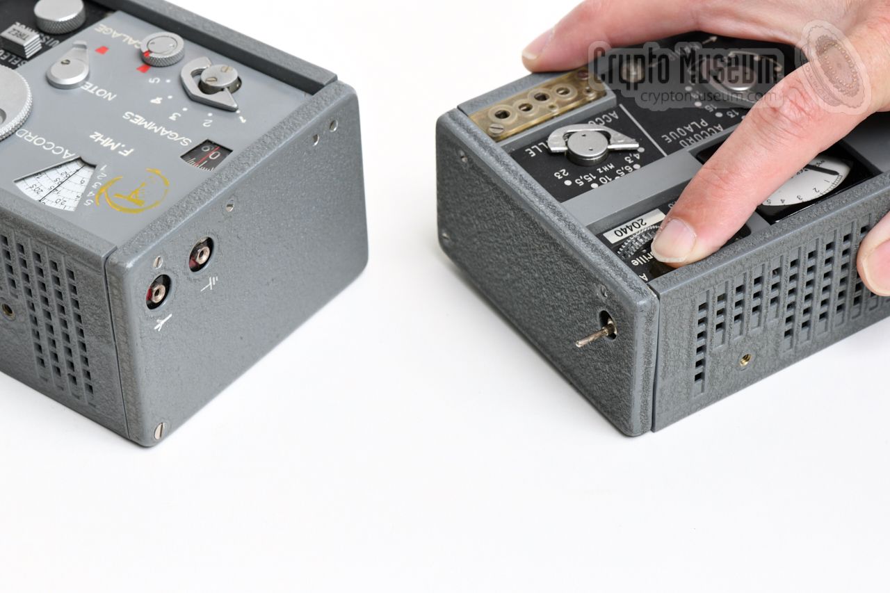
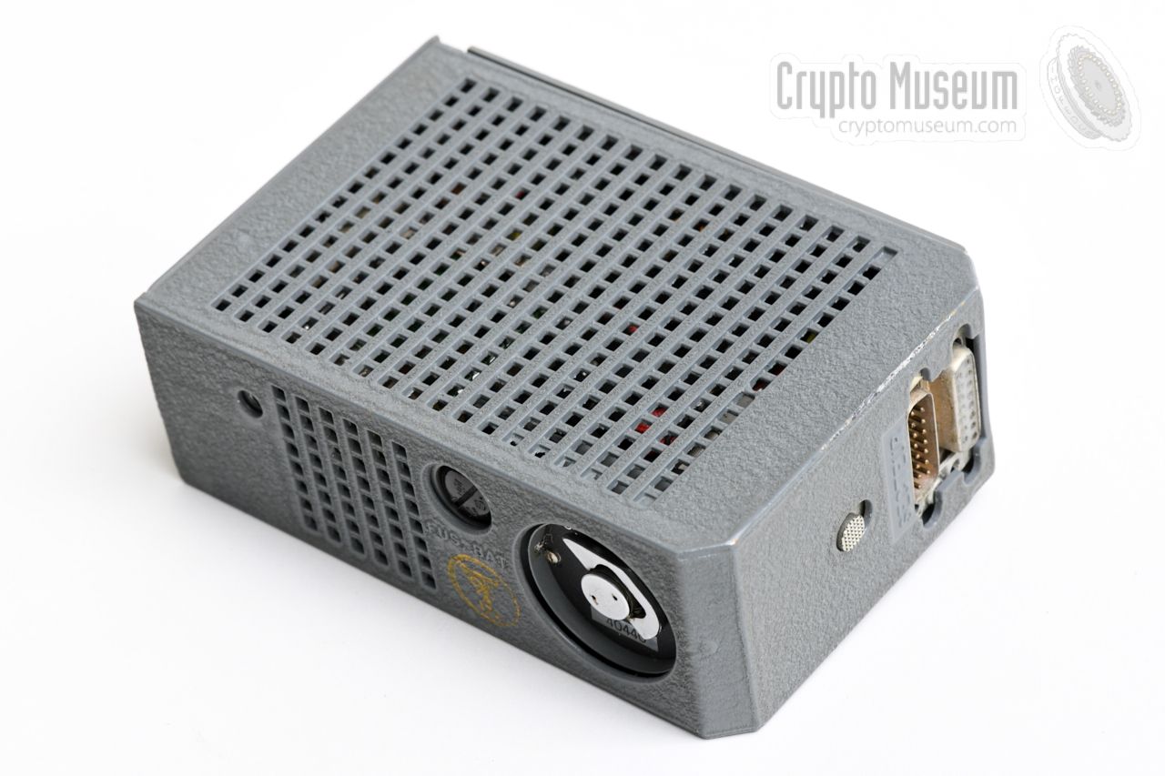
A basic TR-TG-2A radio station consists of four modules – transmitter,
receiver,
power supply unit
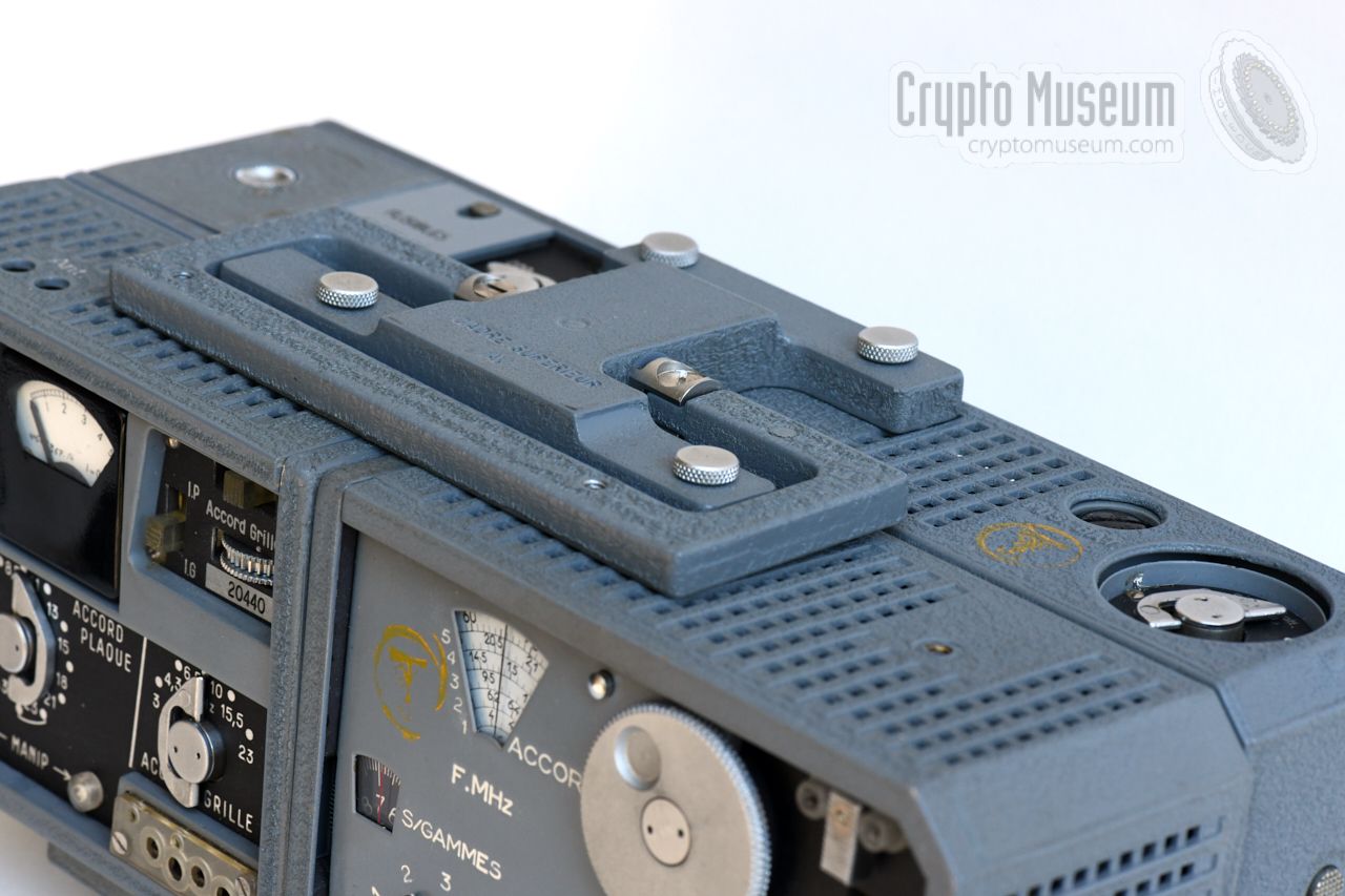
and power selector – held together by two metal
brackets: one at the top
and one at the bottom. The latter can also be
used as a pedestal, allowing the front panel to be tilted somewhat.
The set is constructed in such a way, that the transmitter and receiver are
both at the front, with the power circuits behind them. The diagram below
shows transmitter
(left) and receiver (right).
The receiver
has a 6-band Variable Frequency Oscillator (VFO),
but can also be operated with quarz crystals,
which can be inserted in the socket at the top right.
The transmitter can only be operated with crystals, but has a universal socket
that accepts virtually any type of quarz crystal.
The set can be powered from virtually any AC mains voltage in the world
(105-265V) or from a 6V DC source, such as the battery of a car.
In the latter case, the power selector is used as a power
inverter. The mains PSU can also be used on its own (stand-alone) as a
battery charger.
|
- Special Forces
This version of fhe TR-TG-2A was supplied in a green canvas backpack
with soft padding and space for the (wire) antennas, spare parts, accessories,
etc. It was used by the French Special Intelligence Battalion (13 RDP)
and was known as NSN 5820-14-218-9154
[5].
- Stay-Behind
This version was made especially for
Stay-Behind Organisations (SBO) – also
known as Gladio – and for espionage purposes under control of the French Foreign Office. It came in a small unobtrusive suitcase, or in a
regular executive-style briefcase.
- Receive-only
There was also a receive-only version that consisted of a PSU,
a receiver module and a pair
of earphones. It was used for agents that did not require the need to
transmit, but also as an complenentary receiver for an agent setup.
|
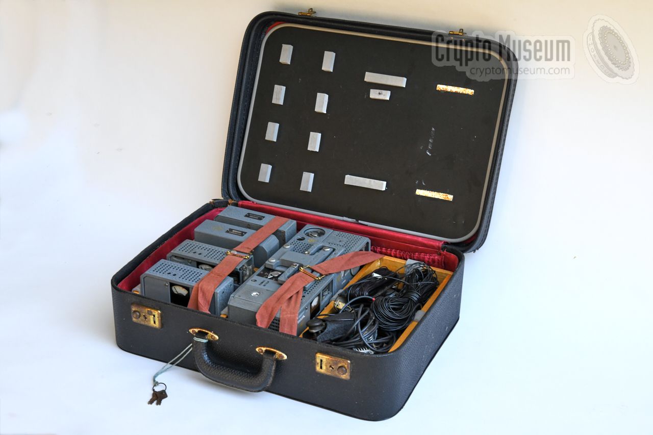
The agent-version of the TR-TG-2A was usually supplied in a common executive-style
briefcase, or in a travel suitcase, such as the one shown in the image on the
right. Inside it is a wooden frame with foam padding, into which the
radio set, its accessories and any spare are fitted.
The case shown here was found with a TR-TG-2A set with
serial number 0440.
|
|
|
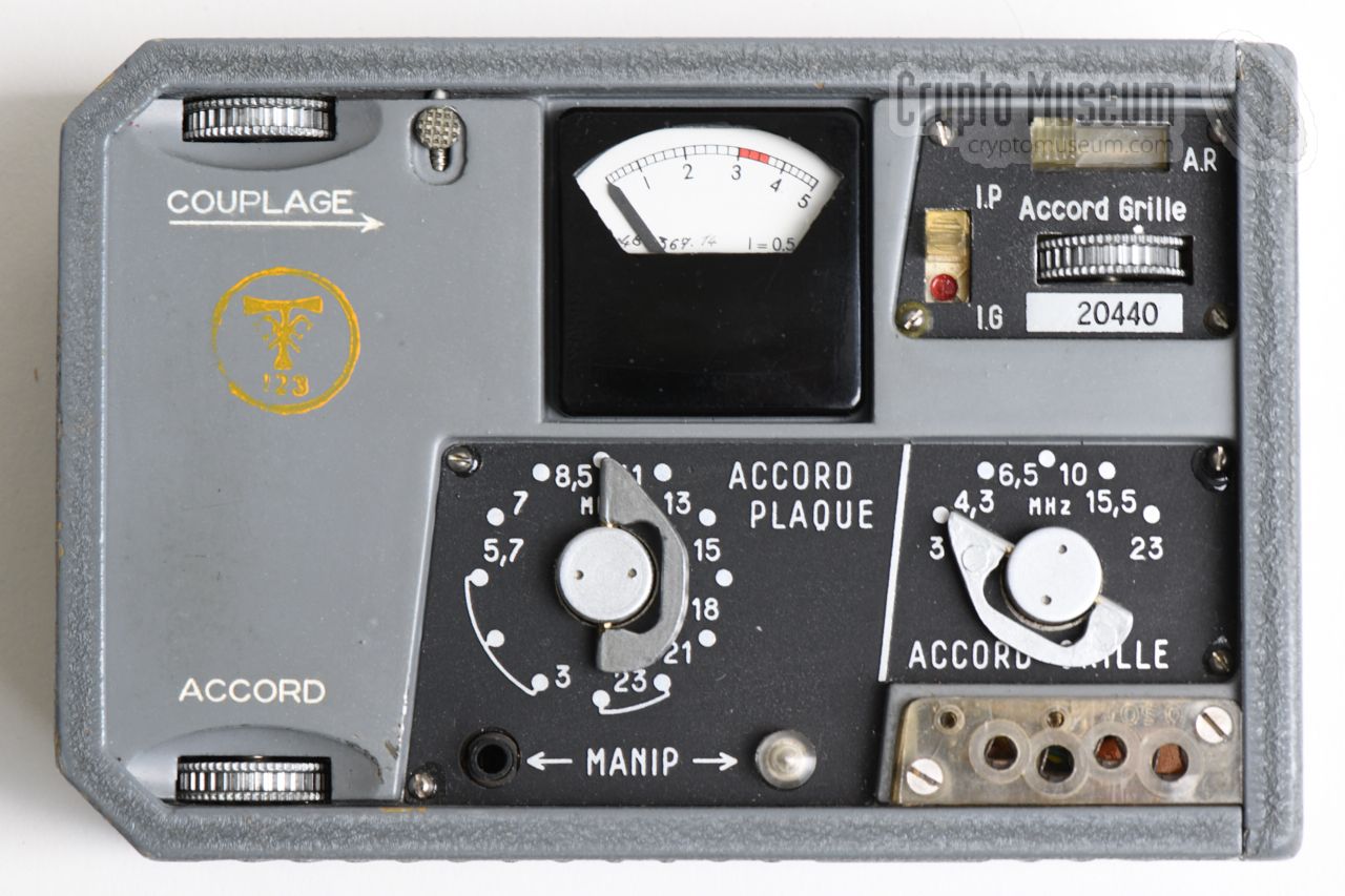
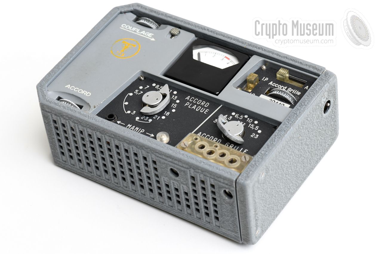
The transmitter is fitted at the front left of the set.
The antenna and counterpoise wires
are connected to the
two sockets at the top left. At the
right it has a movable pin
which passes the antenna signal on to the receiver.
The transmitter is crystal-operated and accepts three different crystal
sizes, which can be fitted in the universal socket at the bottom right.
When transmitting, the tuning controls have to be adjusted for a
maximum reading on the meter.
|
|
|
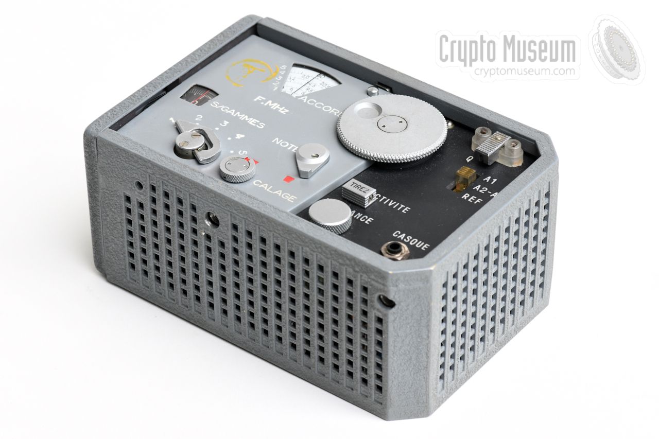
The free-running receiver covers a frequency range of 2.9 to 22.9 MHz,
spread over 6 bands, selectable with a rotary dial at the front. It is
suitable for the reception of AM (phone) as well as CW (morse) signals, in which
case the internal Beat Frequency Oscillator (BFO) is used.
The receiver is fitted to the right of the transmitter.
A pair of earphones can be connected to the 3 mm socket at the bottom right
of the front panel.
The receiver gets its antenna signal from a
movable pin on the adjacent
transmitter.
|
|
|
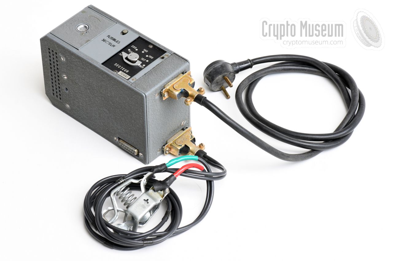
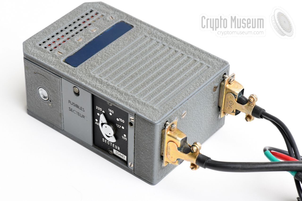
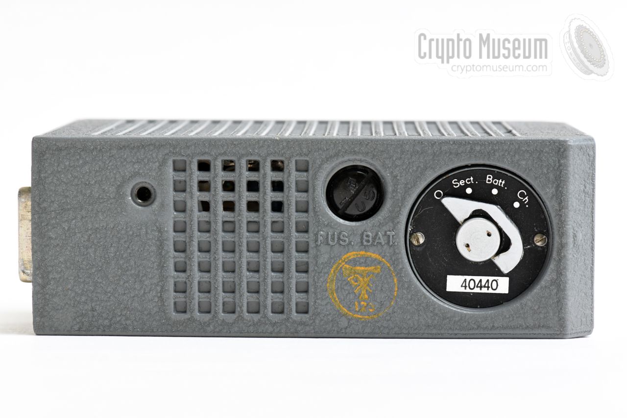
The mains power supply unit (PSU) is fitted at the rear left of the set,
just behind the transmitter.
It is connected to the power selector
at its right, by means of two DB-15 connectors.
The PSU has a rotary selector at the top, allowing it to be powered from a
wide variety of mains AC voltages: 105, 127, 150, 180, 220 and 265V.
It can also be used on its own as a battery charger.
|
|
|
The power selector is fitted at the rear right of the set. It acts as the
central power hub, and is connected to the AC mains, the PSU,
the transmitter
and the receiver.
The unit has a built-in electronic power inverter, that allows the complete
set to be powered from a 6V DC source, such as the battery of a car.
|
|
|
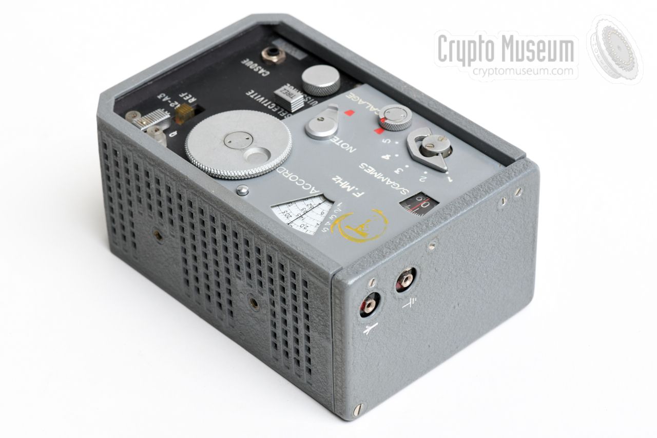
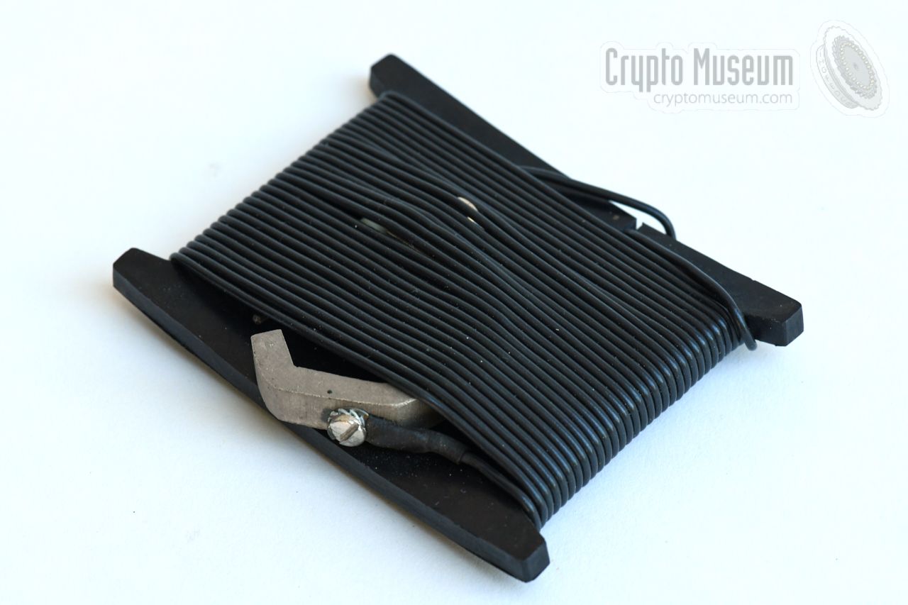
Some units were supplied with a separate tuning box – such as the one shown
here – that can be used as a tuning aid for the transmitter.
It allows the transmitter to be adjusted for
maximum output power, without revealing its presence.
The box connects to the antenna and counterpoise sockets of the
transmitter and contains a set of power resistors that act as a dummy
load whilst tuning. This avoids the transmitter being on the air too long,
and reduces the chance of Radio Direction Finding (RDF).
|
|
|
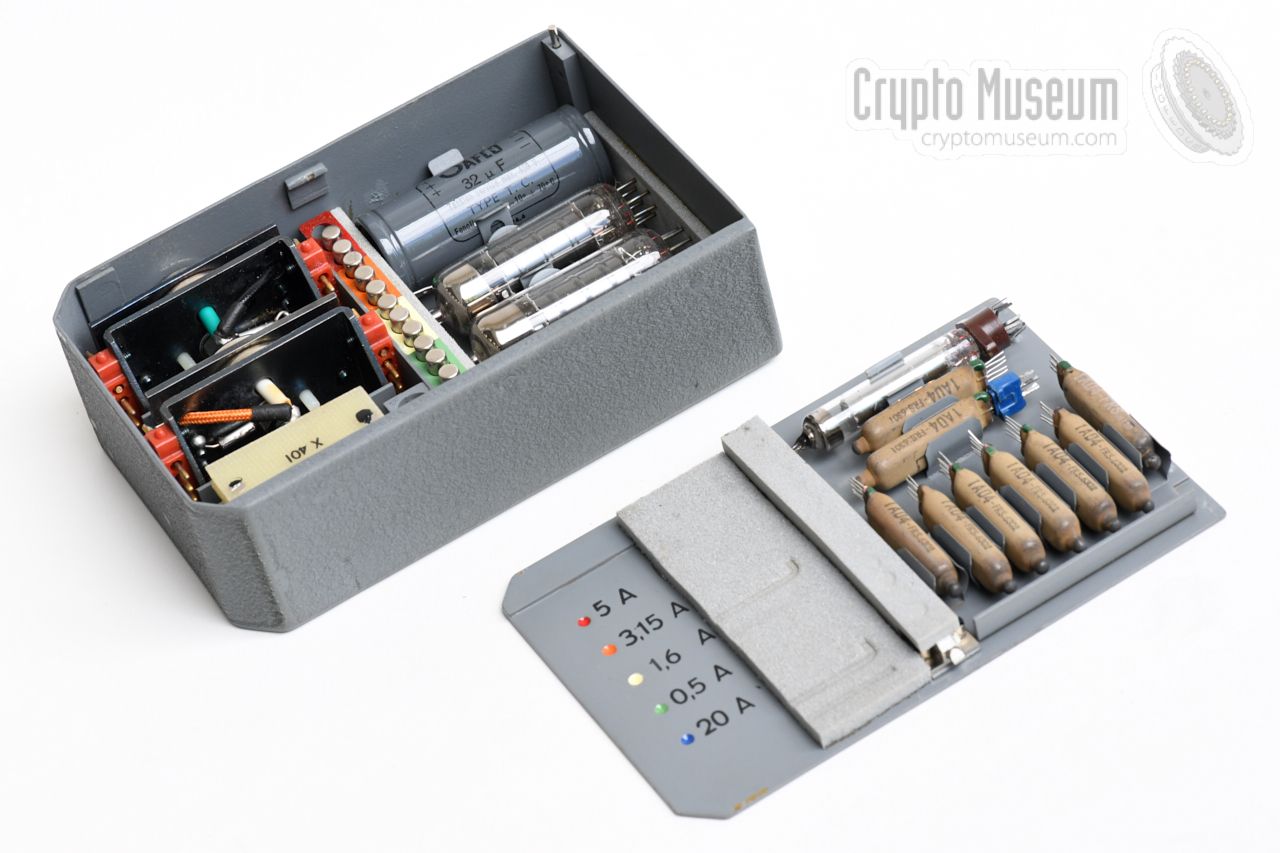
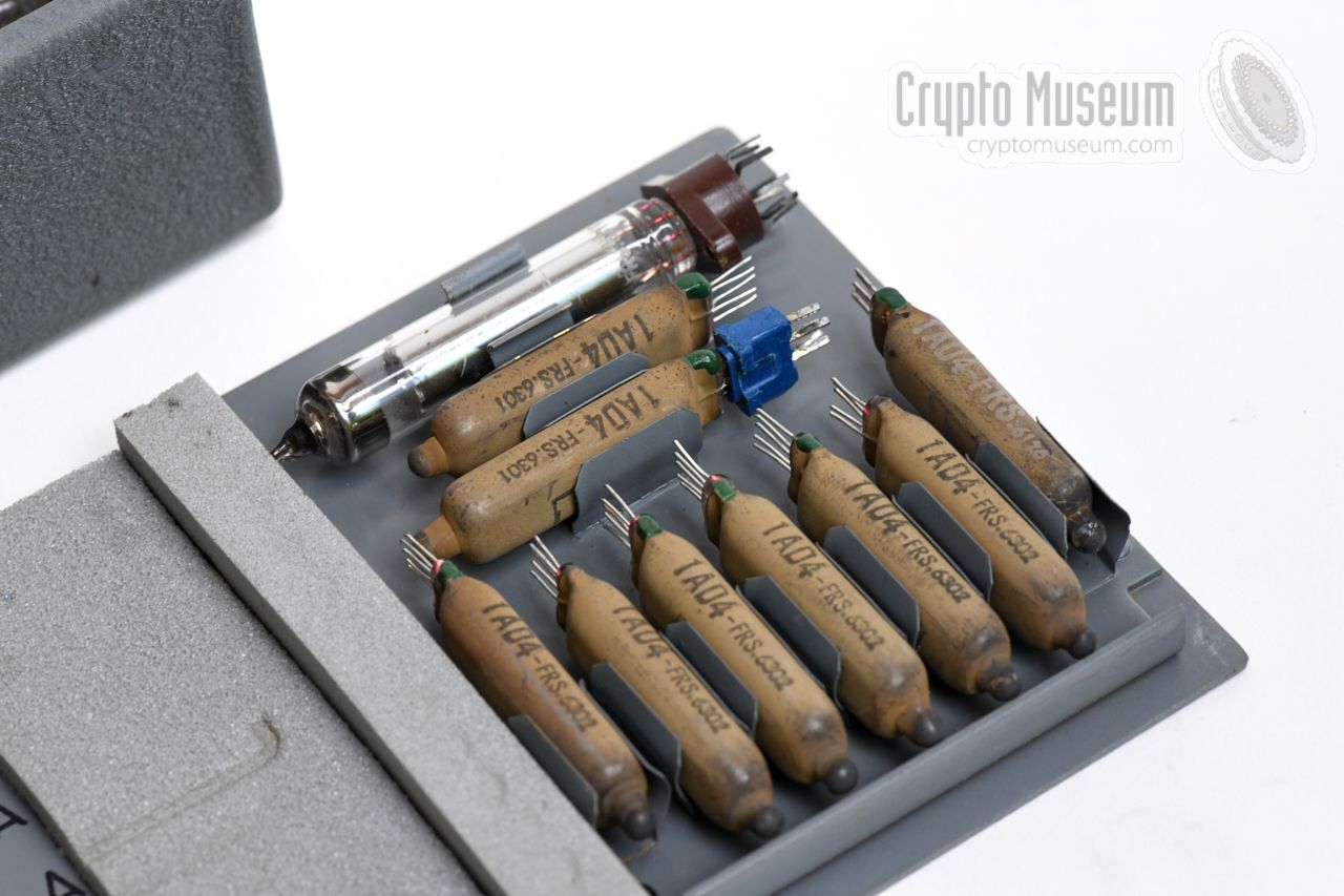
In order to allow the set to be repaired in the field in case of a faillure,
It was supplied with a grey metal box that contains a nice selection of
spare parts, such as fuses, valves, capacitors and even complete sub-circuits.
The image on the right shows the spare parts box with its lid removed.
Stowed in special metal clips on the lid, are the subminiture (pencil) valves.
Two larger valves for the transmitter are stowed in the case itself.
|
|
|
The image on the right shows the wire antenna, which bascially consists of
a long wire, wound onto a pertinax (paxolin) card. The ropes are for attaching
it to, say, a tree.
Additional wires were provided to connecting a suitable counterpoise (ground),
with a special clamp for connecting the ground wire to the water pipe or
the central heating system.
|
|
|
The miniature morse key shown in the image on the right, can be connected
to the MANIP socket of the transmitter, allowing messages to be
transmitted in morse code. Rather than using
the supplied key, some users preferred to connect an alternative key of their
own choice.
Instead of they morse key, the MANIP socket could also be used for connection
of a burst transmitter,
but it is currently unknown whether this was done in practice.
|
|
|
A set of Y-forked earphones, such as the ones shown in the image on the right,
were supplied for the receiver. Their 3 mm jack plug should be installed in the
socket marked CASQUE.
Each earphone has a plastic clip that allow it to be hung over the ear.
The earphones were typical for the era and were in use from the 1960s well
into the 1990s.
|
|
|
|
The set was supplied with a wide range of accesories, such as antenna
wire isolators, mains plugs, mains power splitters and light-bulb adapters
which could be used in houses or hotel rooms without any
free mains wall sockets.
|
|
|
Each TR-TG-2A radio set was supplied with a small (red) booklet with
operating instructions, a maintenance booklet and (in some cases) a full
technical manual. The complete set is shown in the image on the right
and is available for download below.
➤ Operating instructions (French)
➤ Technical description (French)
|
|
|
The block diagram below shows how the main building blocks are interconnected.
The power selector
acts as the central power hub. It takes power from the
AC mains PSU or from an external 6V DC source,
and passes it on to the transmitter and
the receiver. The antenna is connected to the transmitter, which passes its
signal on to the receiver by means of a
movable contact pin.
|
Device Spy radio set Purpose Agent communication Manufacturer Lagier & Cie, Marseille (France) Year 1965 Users French Army, special forces, stay-behind, Foreign Office,
13 RDP intelligence battalion Model TR-TG-2A NSN 5820-14-218-9154 Frequency 2.9 - 22.9 MHz Modulation CW (A1, A2), AM (A3) Mains 102, 127, 150, 180, 220, 260 V/AC Temperature -22°C to +55°C (operation)
|
Output 15 Watts Valves 3 × 6AQ5 Frequency Crystal-controlled
|
Type Superheterodyne Modulation Telegraphy (A1, CW), Voice (A3, AM) Valves 9 × 1AD4 subminiature penthode
|
Mains AC 105V, 127V, 150V, 180V, 220V, 265V Battery DC 6V
|
- 2.9 — 4.7 MHz
- 4.5 — 7.2 MHz
- 6.9 — 11.2 MHz
- 10.5 — 17.1 MHz
- 16.2 — 22.9 MHz
|
|
Each module of the TR-TG-2A is marked with an individual serial number that
consists of 5 digits. The first digit indicates the module (e.g. 1 =
receiver, 2 = transmitter, etc.), whilst the remaining digits form the
actual serial number. The set shown here has serial number 0440.
|
0149 PSU Private collector, France 0152 PWR Private collector, France 0245 RX Crypto Museum, Netherlands 0244 TX Private collector, France 0440 Set Günter Hütter, Austria 0478 Spares Crypto Museum, Netherlands 0524 RX Private collector, France 0526 TX Crypto Museum, Netherlands
|
-
Document kindly provided by Günter Hütter [1].
-
Document obtained from Carlo Brmanti [3].
|
|
|
|
Any links shown in red are currently unavailable.
If you like the information on this website, why not make a donation?
© Crypto Museum. Created: Sunday 12 May 2019. Last changed: Monday, 12 February 2024 - 17:59 CET.
|
 |

|
|
|