|
|
|
|
|

|
|
Spy USSR NKVD KGB GRU
USSR spy radio set · 1942
Tensor or Tenzor 1 (Russian: Тензор) was a
spy radio set,
developed in the USA and built from 1942 onwards
by Silvania 2 near Moscow (Russia). The device was used throughout WWII
by the GRU and the NKVD; the forerunner of the KGB.
After WWII, it was used by the GRU and the KGB,
often as part of an (underground) cache for use before or during an
invasion of Western Europe.
|
The set consists of four same-size aluminium units: transmitter,
receiver,
power supply unit (PSU)
and filter, that can be connected
together via cables to form an operational radio station.
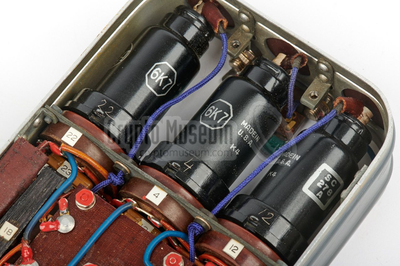
Except for the receiver, all valves are placed externally, which saves space
and prevents the transmitter and PSU from overheating. All text on the bodies
of the cases is in English, and all valves are American.
This was clearly done to disguise its true identity. Furthermore it helped
the GRU agents in operating the set, as many of them were foreign
and did not speak Russian.
|
|
|
The four main units of the radio station are professionally made,
with a keen eye for detail. Each unit measures 17.5 x 10.7 cm
with rounded corners, and consists of a strong metal frame with
removable lids at the top and at the bottom.
Each cover is strengthened by means of several embossed rigs and
impressed windows, with clear engraved markings in the English
language. Furthermore each unit is painted in two different
colours (two-tone), which gives it a professional look and feel.
The knobs are made of bakelite or – with the early version –
machined aluminium.
|
|
|
|
According to the British National Archives, the Tensor design was
a gift from the Americans [7].
It is believed that the set was in production until the late 1950s.
After WWII, Tensor was mainly distributed by the
GRU to agents (often in Western Europe)
that could be activated in the event of a war. This is confirmed
by the fact that quite a few Tensor sets were found after the
Cold War,
in caches in and around Vienna (Austria). The set featured here, was found
in an attic in the former DDR after the reunification of Germany.
It had probably been kept there by a former GRU agent.
|
-
In anatomy, the English word Tensor is used for a muscle that thightens
or stretches part of the body. In Russian, the word Тензор (Tenzor) has
the same meaning.
-
Silvania was (and is) a Russian valve (tube) manufacturer.
|
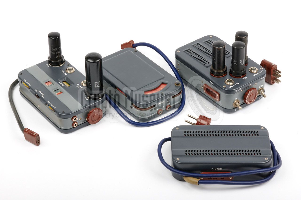
The diagram below shows all four units of the Tensor radio station,
plus some of the accessories, ready for use. At the top centre is the
mains filter unit that passes the mains voltage to the
Power Supply Unit (PSU) at the centre of the diagram.
A 9-position rotary switch is used for selecting the
desired mains voltage. In most West-European countries it should be set
to 240V. Three rectifier valves are fitted externally at the top surface
of the PSU.
The PSU provides the necessary voltages for the receiver (left)
and the transmitter (right). The transmitter valves are also
fitted externally.
The three receiver valves are fitted internally. The receiver delivers
its audio directly to a pair of (supplied) headphones.
A miniature morse key (visible at the front right) is connected directly to the transmitter.
Also visible in the diagram are the separate wire antennas
for the transmitter and the receiver, that allow full duplex operation.
An external antenna tuning unit is provided to allow the antenna
to be matched to the transmitter.
More detailed information is provided below.
|
|
There are two known versions of the Tensor radio station:
|
- Tensor Mark 1 · 1942
This is believed to be the initial version of the set,
introduced in 1942.
Its PSU has just two 5Z4 rectifying valves and the transmitter has
two circular windows for reading off the frequency. Furthermore it is
supplied with an older type morse key. The large knobs of the PSU's voltage
selector and the transmitter's band selector are made of aluminium.
- Tensor Mark 2 · 1944
From 1944 onwards, the PSU was given three 5Z4 rectifying valves and the
transmitter had rectangular windows for reading off the frequency.
It was supplied with a later type of morse key.
The large selectors – and some other parts – are made of brown or black
bakelite. It is believed that most
Tensor units that were used during the Cold War, are of this type.
The Tensor features on this page is a Mark 2 version
that was made in 1956.
|
During the Cold War,
the complete Tensor radio set was supplied in a wooden box that measures
41 x 28 x 16 cm and weighs approx. 4.5 kg.
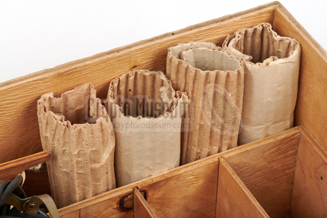
Each part is individually packed in protective grease paper to allow it
to be stored for an extended period of time.
The box was often hidden in a dry place such as an attic.
Sets that were hidden in underground caches were usually packed in an
hermetically sealed metal container, to protect it against moist,
fungus, etc.
|
|
|
When the Tensor set had to be stored in a moist place – usually as part
of a secret underground cache – it was packed inside the watertight
metal container shown in the image on the right.
The metal container shown here was found in the late 1990s in Vienna
(Austria), when road works unexpectedly revealed a former Cold War
USSR/Russian cache.
Inside the container was a complete intact Tensor Mark 2
with accessories
and operating instructions in German.
It is now on display at the Austrian Signals Museum [3].
|
|
|
|
|
Canvas carrying bag
wanted
|
|
|
According to a wartime German publication of 1943, Tensor sets were
commonly supplied in the canvas carrying bag shown in the image on the
right [2]. The bag has several pockets for the accessories and spare
parts. Alternatively, a strong leather bag was issued in some cases [5].
It is believed that this bag was not supplied with the Tensor radio sets
that were issued during the Cold War, as these were stored for an extended
period of time, without immediate action.
|
|
|
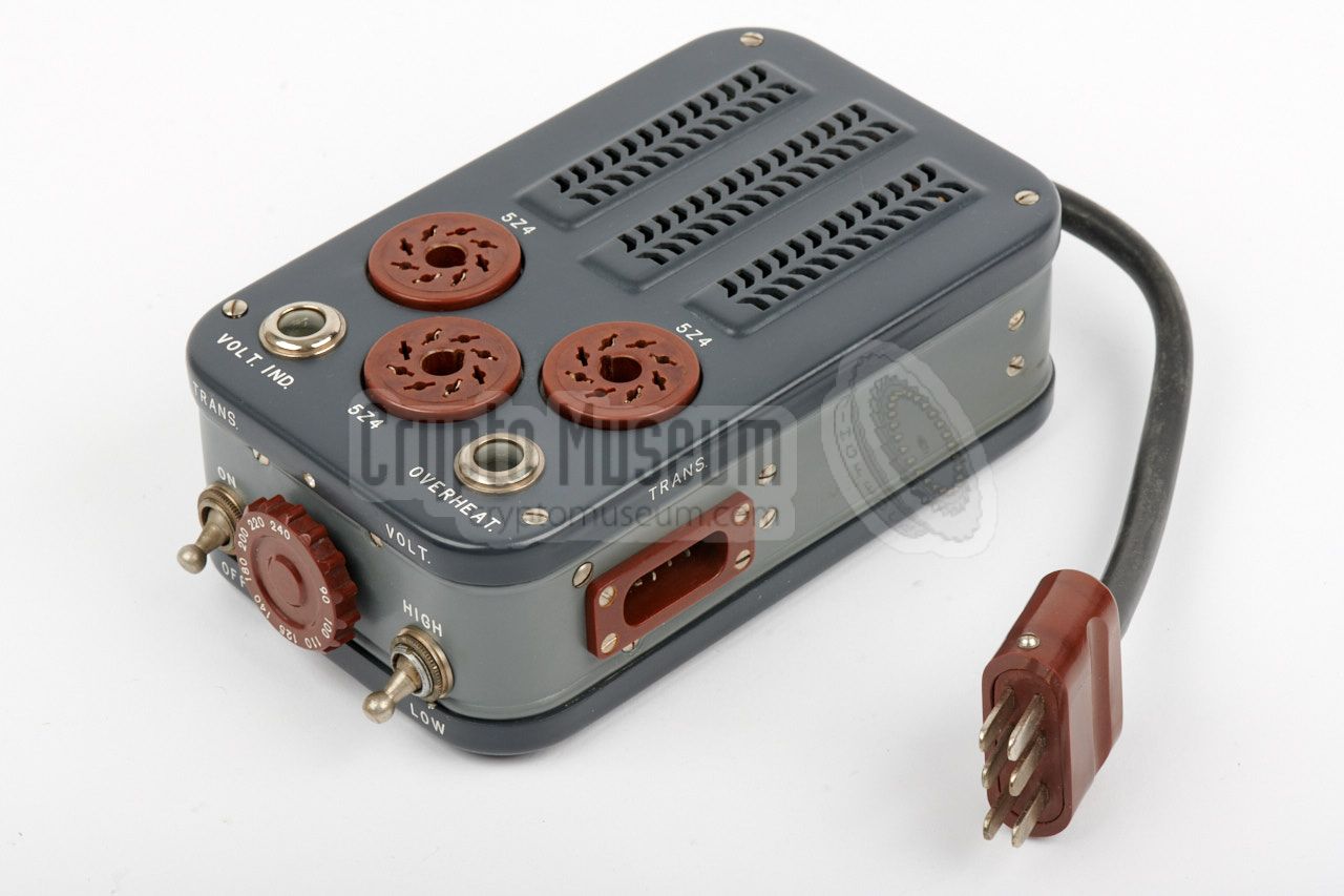
The Power Supply Unit (PSU) acts as the central hub to which all
other units are connected. It has a fixed cable to which the mains
voltage should be supplied, via the filter unit. The
correct mains voltage should be selected with the large rotary knob
at the front. At the top are three sockets in which the 5Z4
rectifying valves should be placed.
The PSU has two output sockets: one for the receiver (left) and one
for the transmitter (right). The pins of these two sockets are
different, so that the plugs can not be swapped accidentally.
|
|
|
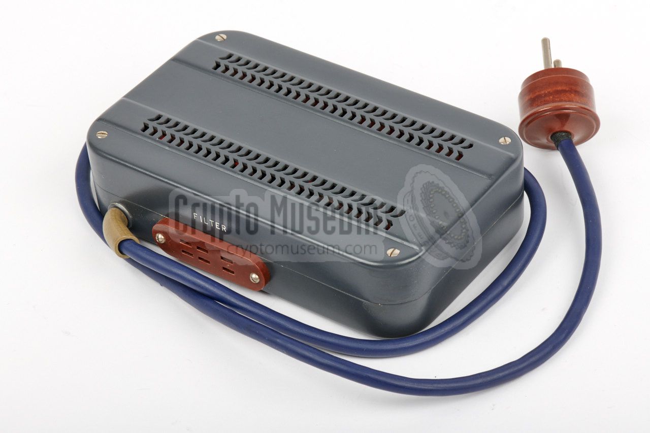
The AC mains voltage is not supplied directly to the PSU,
but via the filter unit shown in the image on the right.
The unit has a fixed cable with a mains plug at the end,
and a custom socket that accepts the PSU described above.
The filter unit contains four large electrolytic capacitors
and some resistors, that are used for stabilisation of the
DC voltages created by the PSU. As the capacitors are relatively
large and do not fit inside the PSU, they are instead mounted
inside the filter unit.
➤ View inside
|
|
|
|
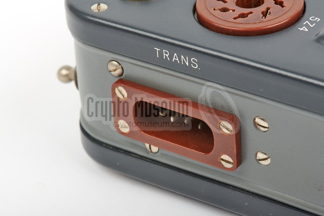
The transmitter's power cord should be connected to the
rightmost power socket
of the PSU, which is marked 'TRANS.'.
Furthermore, a morse key should be connected
to the KEY socket at the right, and a suitable dipole antenna and
counterpoise to the antenna sockets
at the rear.
|
The transmitter can be adjusted freely by using the Variable
Frequency Oscillator (VFO), but it is also possible to select the
frequency by installing an appropriate crystal 1 in the XTAL socket at
the left, as demonstrated in the image on the right.
At the top surface are two ceramic valve sockets: one for each
transmitter stage. The leftmost
one holds the metal 6F6 oscillator valve, whilst the large
metal 6L6 PA-valve should be installed at the right.
Each stage has its own frequency dial, which can be adjusted
at the front edge, whilst the frequency is read from a window
at the top.
|
|
|
|
The transmitter is suitable for the 3.7 to 14.3 MHz frequency range,
divided over four bands (or ranges as they are called here)
selectable with the large rotary knob
at the right side. The selected range is visible in a
rectangular window,
just above the frequency readouts.
At the rear edge are two indicator
lamps that are used as an aid when tuning the transmitter stages.
The leftmost one provides an indication of the oscillator activity.
The rightmost lamp is used for tuning the antenna circuit or
the amplifier stage (PA), selectable with a slide switch at the centre
of the front edge.
The transmitter has a power output of 13W or 30W, selectable with
a toggle switch on the PSU.
|
-
This is a unique feature of this transmitter, that is not
commonly found on other spy radio sets of the era.
|
|
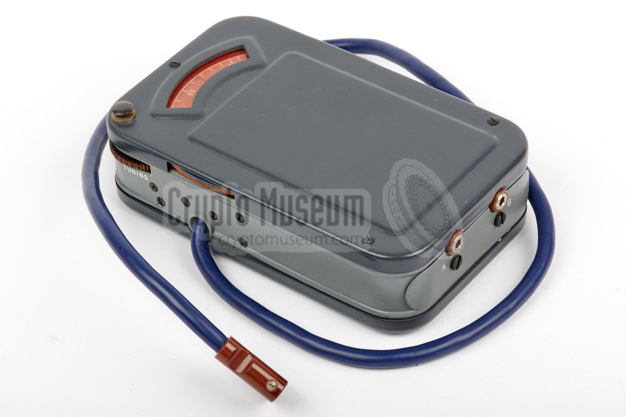
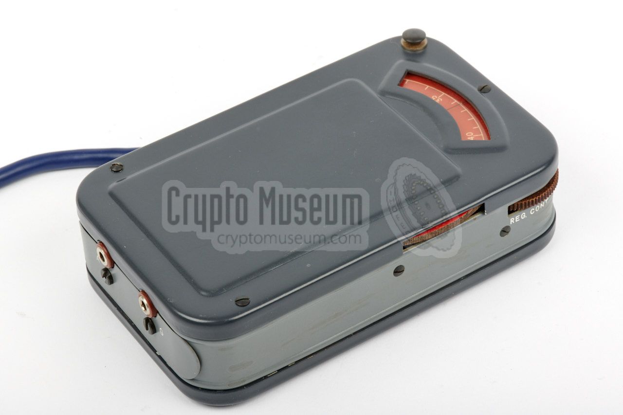
The receiver is housed in a case that is very similar to that
of the transmitter, but its valves are mounted internally.
The receiver's power cord should be connected to the leftmost
power socket
of the PSU,
which is marked REC.
A suitable antenna and counterpoise should be connected to the
terminals at the rear, whilst a pair of (supplied) headphones
should be connected at the front.
|
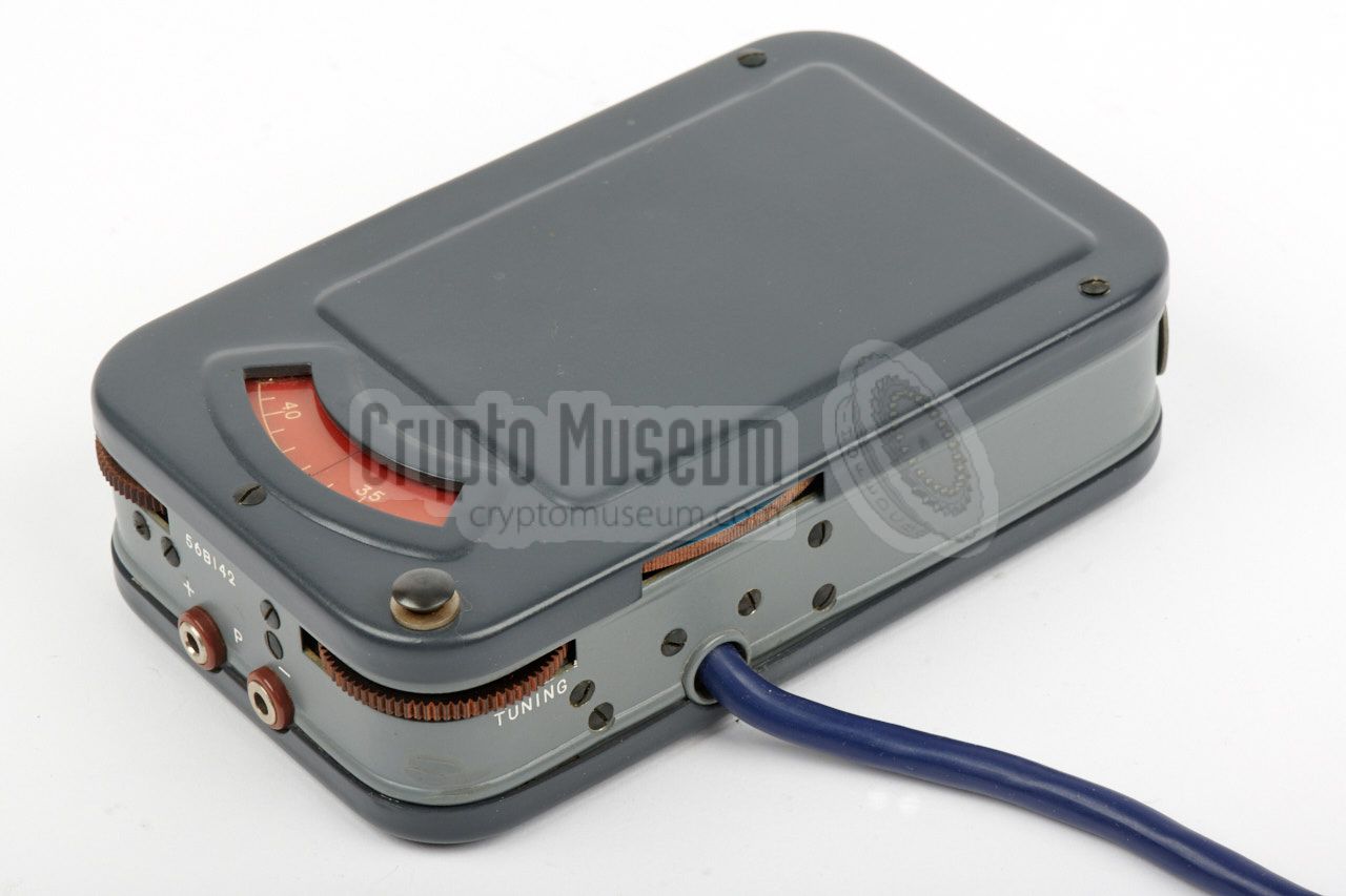
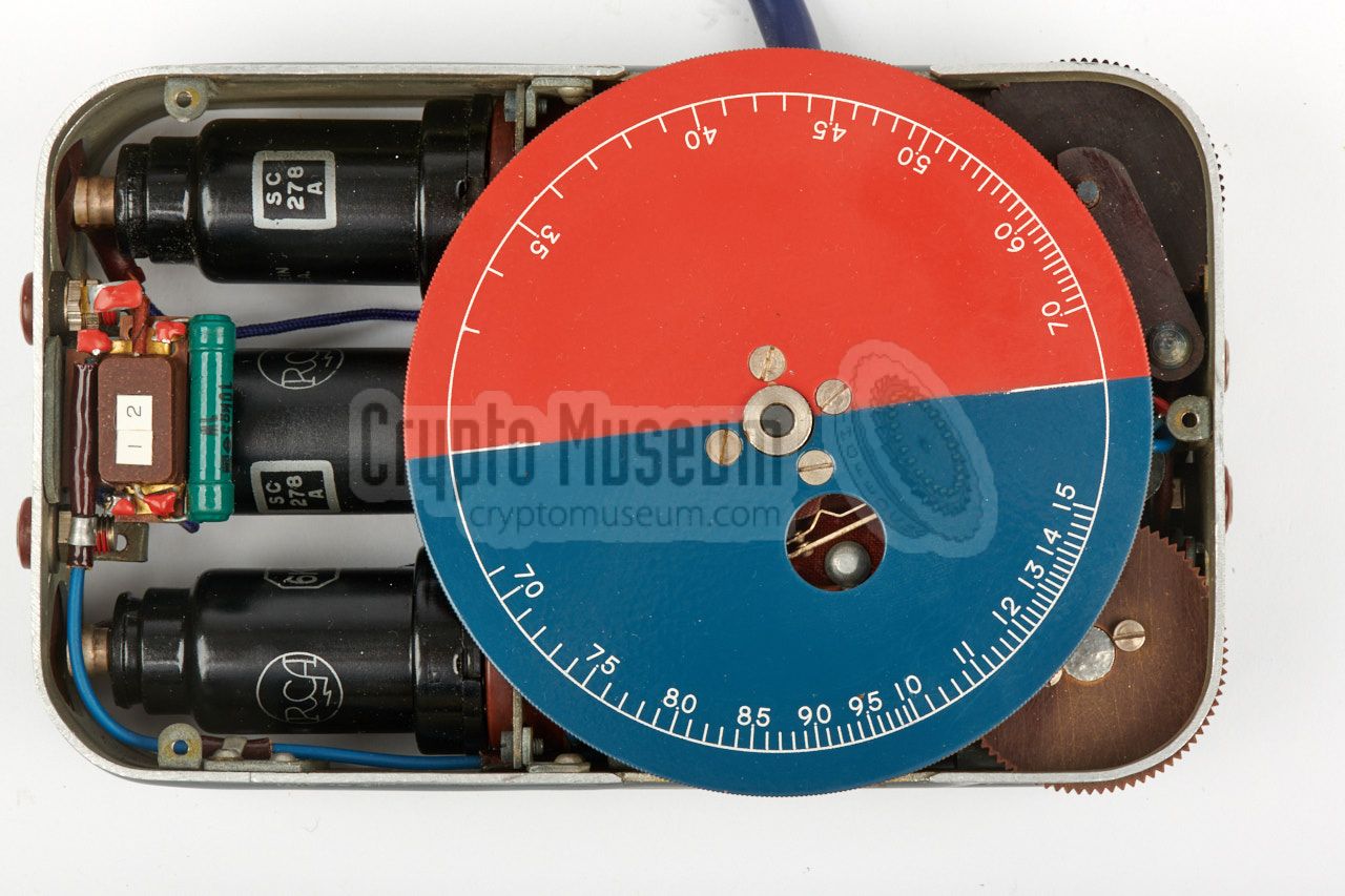
The receiver's VFO can be adjusted freely over the entire 3.3 to 15 MHz
frequency range, which is divided over two bands: 3.3 - 7 MHz (red)
and 7 - 15 MHz (blue). Selecting the
required band is not necessary as this is done automatically
by an internal switch when turning the dial from the red to the blue
section of the frequency scale.
With the wartime Tensor Mark 1, the receiver's circuit diagram was fitted
on the top cover, in the large rectangular area behind the frequency scale.
On the Mark 2 version — shown here — the diagram is omitted
and the area is blank.
|
|
|
|
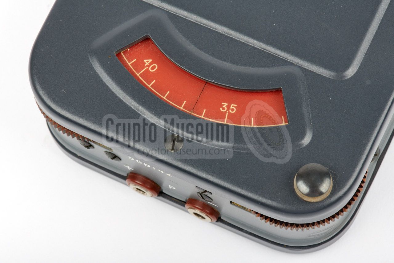
Use the fine tuning knob at the front right corner to adjust the receiver
to the desired frequency. It is also possible to use coarse tuning — available
at both sides of the receiver — but the scale release knob at the front right
has to be pressed whilst doing turning the coarse dial in order to prevent
damage to the Pertinax dial
that is driven by a small metal cogwheel (see interior below).
At the front left corner is a knob that controls regeneration of
the receiver and hence the volume.
|
A miniature morse key was supplied with the set, such as the one
shown in the image on the right. Earlier Tensor versions may have
been supplied with older model morse keys.
The morse key is connected to the two banana sockets at the right
side of the transmitter, where the operator could also connect an
alternative morse key.
|
|
|
The Tensor was supplied with a suitable pair of headphones,
such as the one shown in the image on the right. It was made
in the USSR and has caps made of synthetic rubber.
Other types of headphones are known to have been supplied as
well.
|
|
|
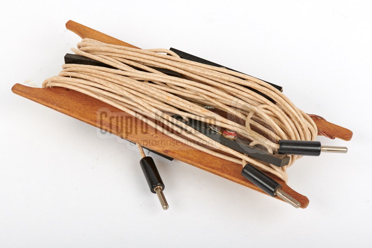
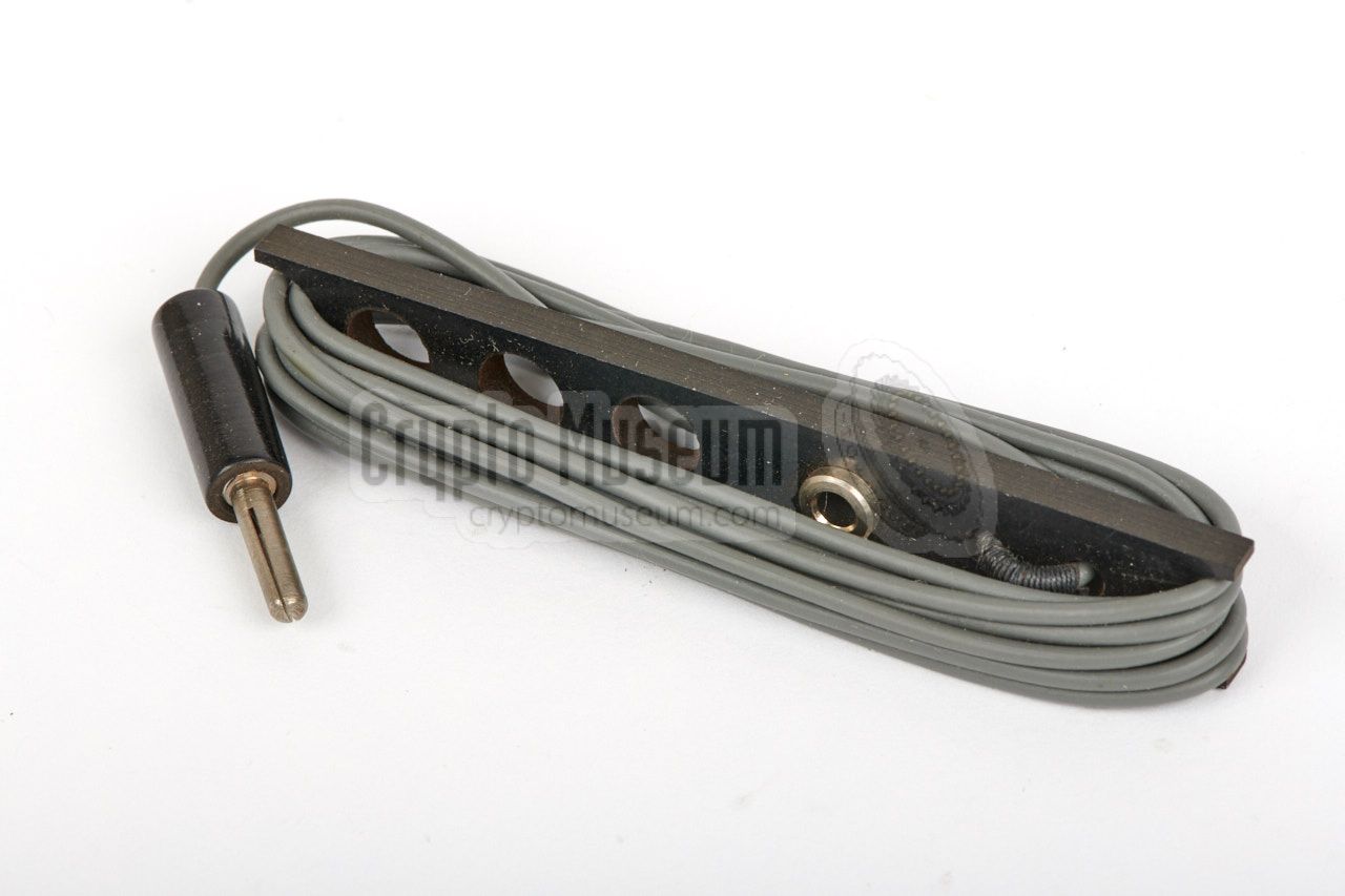
Various wire antennas are supplied, each of which is wound onto
a piece of wood, as shown in the image on the right. The transmit
antenna has several taps, to allow it to be matched
to the desired frequency band more accurately.
Seperate antennas and counterpoise wires are provided for transmitter
and receiver, to allow full duplex operation (i.e. no switching
of the antenna between transmitter and receiver).
|
|
|
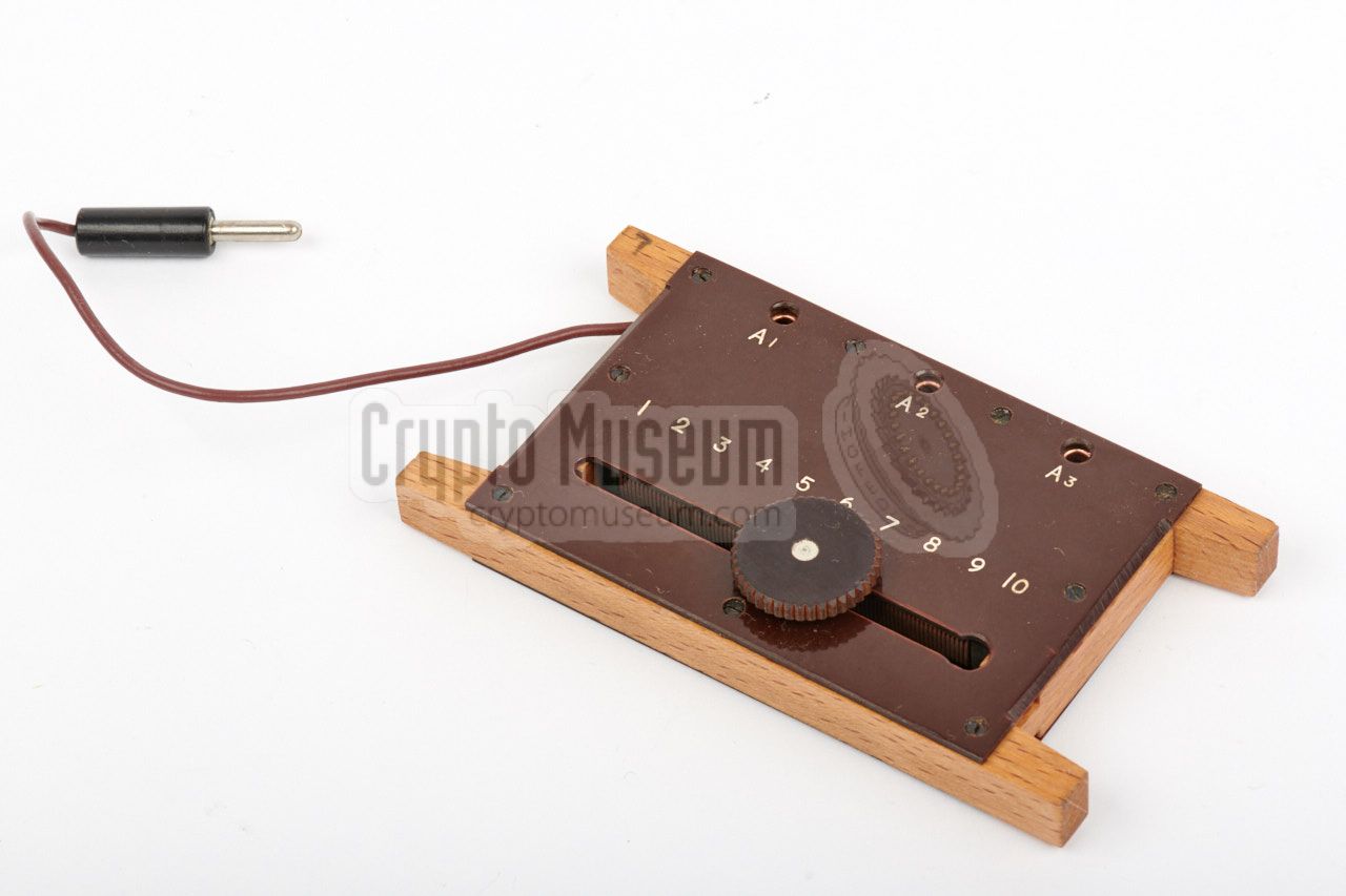
In order to match the antenna to the transmitter on a given
frequency band, a small antenna tuning unit is provided.
Three taps of the transmit antenna are connected to the
tuner, whilst the tuner is connected to the antenna socket
of the transmitter.
The exect operating procedure of the tuner is described in
the manual.
|
|
|
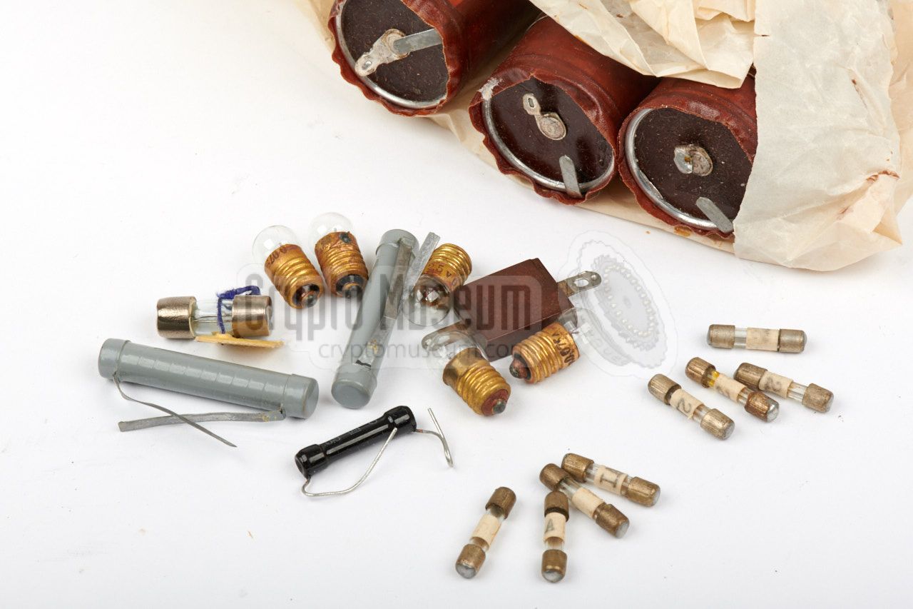
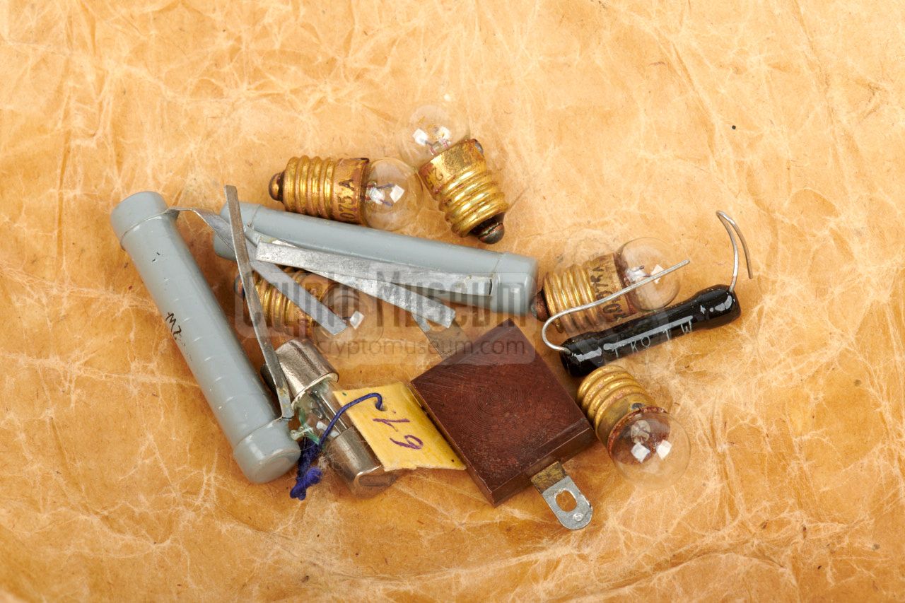
In order to allow for small repairs in the field, the set was
supplied with a selection of spare parts, including:
- Spare valves
- Resistors
- Capacitors
- Light bulbs
- Fuses
The image on the right shows some of the smaller spare parts
as they were found with the Tensor featured here.
➤ Full spares list
|
|
|
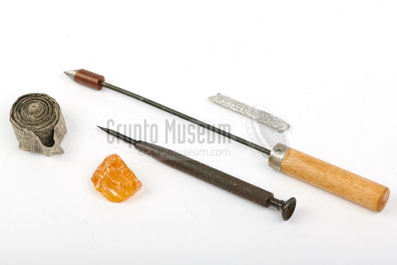
A selection of simple tools was supplied for carrying out
basic maintenance and small field repairs. The image on the right
shows the tools that were found with the Tensor featured here.
The large item with the wooden grip, is a soldering iron, that
should be heated in a fire prior to use. Also supplied are solder,
a piece of resin, a screwdriver and insulation tape.
|
|
|
|
|
Operating instructions
wanted
|
|
|
Each Tensor station was supplied with brief operating instructions
in the local language.
At present, no example of these operating instructions are available.
You can help us expanding this page by providing a copy
or a scan of the instructions, in whatever language.
➤ Contact us
|
|
|
|
|
Transmission schedule
wanted
|
|
|
Apart from the operating instructions, each set came with a personalized
set of tables and instructions for the agent, for contacting the Russian
Centre. These tables contain detailed transmission schedules for a given
time, day, week and month, frequencies, call signs, etc.
The image on the right shows a single page of the transmission schedule for
correspondent number 1742, as it was discovered in a Russian
cache in Austria in 2007 [6].
➤ Download the schedule in PDF
|
|
|
|
The transmission schedule was supplied in printed form as well as on photo
film, so that it could be hidden more easily and reproduced whenever necessary.
The schedule consists of 1 page with global instruction and 10 pages with
frequency, time and call sign tables. The schedule featured here was
discoverd in 2007 and reproduced
from the original film in 2017 by Eric Kelley [6].
|
- Instructions
Anweizungen zur Arbeit
Operating instructions
- Program (2 pages)
Das Program der Verbindung des Korresp. Nr. 1742
mit dem Zentrum Nr. 2 oder Nr. 1
Transmission schedule between Agent 1742 and Centre 2 or 1
- Tabelle Nr. 1
Die Zeit der täglichen Arbeit des Korresp. Nr. 1742 mit dem
Zentrum Nr. 2 oder 1
Time table for days of the month between Agent 1742 and Centre 2 or 1
- Tabelle Nr. 2
Arbeitsfrequenzen für tägl. Arbeit des Korresp. Nr. 1742 m. Zentrum 2
Frequencies for daily operation of Agent 1742 with Centre 2
- Tabelle Nr. 3
Arbeitsfrequenzen für tägl. Arbeit des Korresp. Nr. 1742 mit Zentrum 1
Frequencies for daily operation of Agent 1742 with Centre 1
- Tabelle Nr. 4
Rufzeichen und Koeffiziente des Korr. Nr. 1742, des Zentrums 2 oder 1
Call signs and check numbers for a given time of the day and month
- Tabelle Nr. 5 (3 pages)
Funkunterlagen für die Arbeit auf Kontroll-freq. des Korr. Nr. 1742
mit Zentrum 2 od. 1
Information for operating on check frequencies
- Tabelle Nr. 6
Einseitige Lehrsendungen mit Tonschwankungen
Unidirectional exercise transmissions with tone fading
|
All text is in German, which means it
was intended for a German-speaking agent. If you look carefully at the second
page of the Program (2), you can faintly see some Russian text bleeding through
the page, which suggests that the film was prepared in Russia.
In the text, the word correspondent is used for the agent, whilst the
Russian base station is identified as Centre.
➤ Download the complete transmission schedule in PDF
|
|
The main parts of the Tensor spy radio set are housed in four
similar metal enclosures that hold the transmitter, the receiver,
the power supply unit (PSU) and a mains filter unit. The cases
are made of light metal alloy, of which the shapes have been pressed.
The cases are painted in two tones of grey, with white engraved
lettering. Each case consists of a body and two lids: one at the top
and one at the bottom. The serial number of each unit is engraved
on the exterior of the bottom and the interior of each lid.
The sections below describe the interior of each unit.
|
|
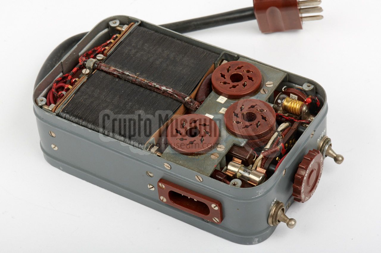
The transmitter is housed in a metal case that measures
17.5 x 10.5 x 4.8 cm (without the valves) and weighs approx.
1100 grams when the valves are fitted. It has two removable
lids: one at the top and one at the bottom, each of which is
held in place by four recessed screws along the edge.
|
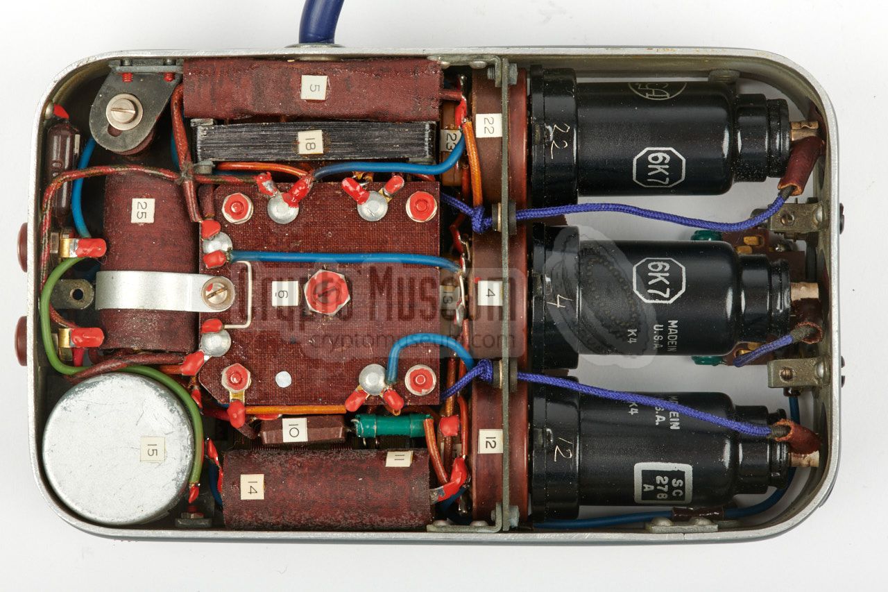
Remove the screws from both sides and remove the two covers.
This will expose the transmitter's interior. The image on the
right shows the upper section that holds the two frequency scales
(each with the four ranges printed in distinct colours),
the band selector, with the same colours,
two indicator lamps and the two valves sockets.
The bottom side contains the tuned circuits and the passive
components. At the centre are the large coils of the PA and
antenna sections. At the right is the oscillator in a separately
shielded section, with the oscillator coil at the centre.
|
|
|
|
The unit is extremely well-built with a keen eye for the smallest
detail. All parts are identified by numbers that correspond to
the circuit diagram.
|
|
The receiver is housed in a metal case that measures
17.5 x 10.5 x 4.7 cm and weighs approx. 936 grams.
It has two removable lids: one at the top (held in place
by three recessed screws) and one at the bottom (held in place by
three large bolts). Remove them to get access to the interior.
|
Actually, the user normally only needs to have access to the
bottom section, as that is where the three 6J7 valves are located.
In order to remove the valves, the Pertinax cover panel
below the antenna terminals has to be removed first.
It is held in place by two black screws.
The image on the right shows the interior of the receiver, as seen from
the top. The frequency dial is prominently visible at the left
and covers most of the circuits underneath. The dial is made
of Pertinax and is actually a big cogwheel, that is driven by a smaller one
on the fine tuning knob.
|
|
|
The frequency dial has a red and a blue half, each representing one
of the two frequency bands that are supported by the receiver. A small
switch, hidden under the dial, automatically selects the appropriate
band when turning the dial from the red to the blue section. The
band selector switch is visible through a hole
in the dial and is driven by a notched disc on the dial axis.
The receiver is built around three identical 6J7 valves that form
the RF, detector and audio stages. In order to remove the three 6J7 valves,
the small cover panel near the antenna terminals has to be removed first.
Resistor R7 is not present is the circuit diagram published in Louis Meulstee's
book Wireless for the Warrior Volume 4 [1], but has been added in the Polish
circuit diagram [B].
|
|
The PSU is housed in a metal case that is similar to that of
the transmitter and receiver. It has the same length and width,
but is somewhat higher in order to accomodate the large AC transformer.
The case has a lid at the top and bottom, each of which is
held in place by four recessed screws.
|
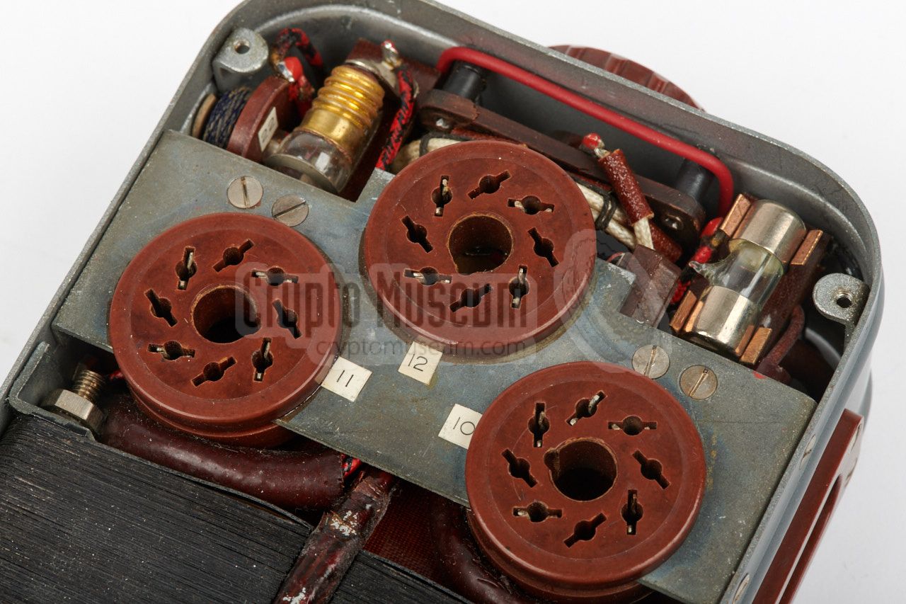
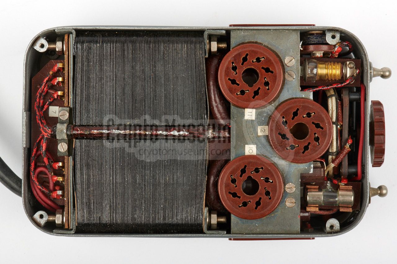
The interior of the PSU can be accessed by removing both covers.
About half the available space is taken by the mains transformer,
which is tightly fitted between the sides of the case.
The remaining half — visible in the image on the right —
holds the sockets for the three rectifying valves, the power selector,
the indicator lamps and the remaining passive components.
Note that a neon lamp is used to indicate the selected HT voltage
and, hence, the transmitter's power output (which can be either 13 or 30 Watts),
depending on the position of the VOLT switch.
|
|
|
|
A remarkable feature of this PSU is the absense of any (electrolytic)
capacitors for stabilisation of the DC voltages. These capacitors
are present but are located inside the separate filter unit
– that is connected between the PSU and the AC mains –
probably because of their dimensions.
|
|
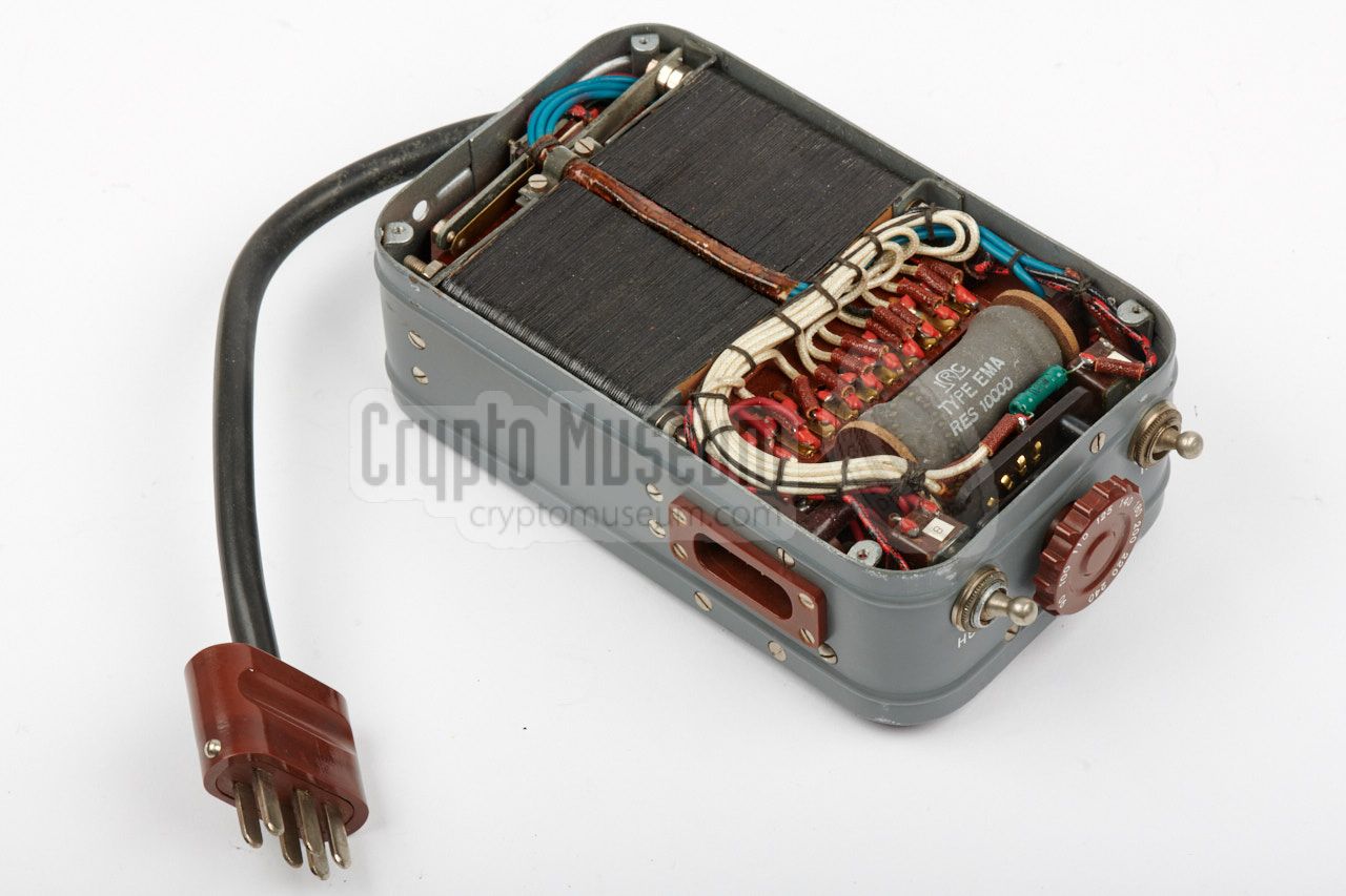
The filter unit has the same dimensions as the transmitter and
the receiver, and weighs 765 grams. Although it is a separate
unit that is connected between the mains and the Power Supply Unit
(PSU), it is actually an integral part of the PSU, as it contains
the electrolytic capacitors (and some resistors) that are needed
for stabilisation of the various DC voltages provided by the PSU.
|
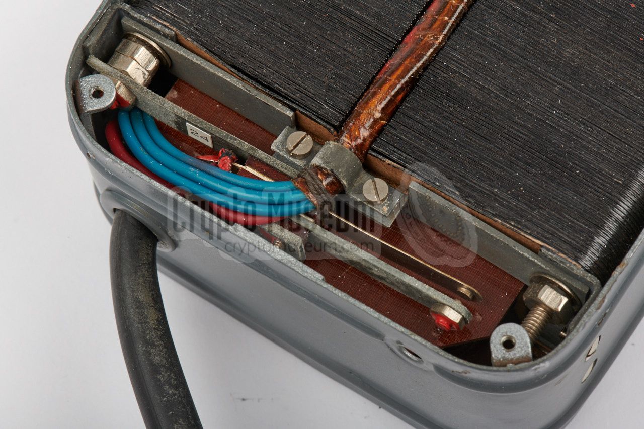
For this reason the filter unit has a 6-pin socket to which
the PSU is connected. Two pins of this connector provide the mains
AC voltage directly to the PSU, whilst the other lines bring the DC voltages
provided by the transformer and the rectifying valves inside the PSU
back to the filter.
At the time the Tensor set was produced, the quality and life cycle
of electrolytic capacitors was largely unknown and unpredictable.
For this reason, a set of replacement capacitors was supplied with the
kit. With the supplied soldering iron,
the operator was able to do a field repair.
|
|
|
|
All four electrolytic capacitors are specified at 20µF.
Although their quality is unpredictable, the ones in the
device shown above still have a capacity of 17µF, which is well within
their original specification. Capacitors of this aga have to be
rejuvenated from time to time (see below).
|
|
The Tensor spy radio set featured above was in mint condition
when it was rediscovered, which means no restoration of the
exterior was necessary. Furthermore all movable parts (switches,
dials, etc.) were still freely movable and all cables were soft
(i.e. not rigid and brittle) and intact.
|
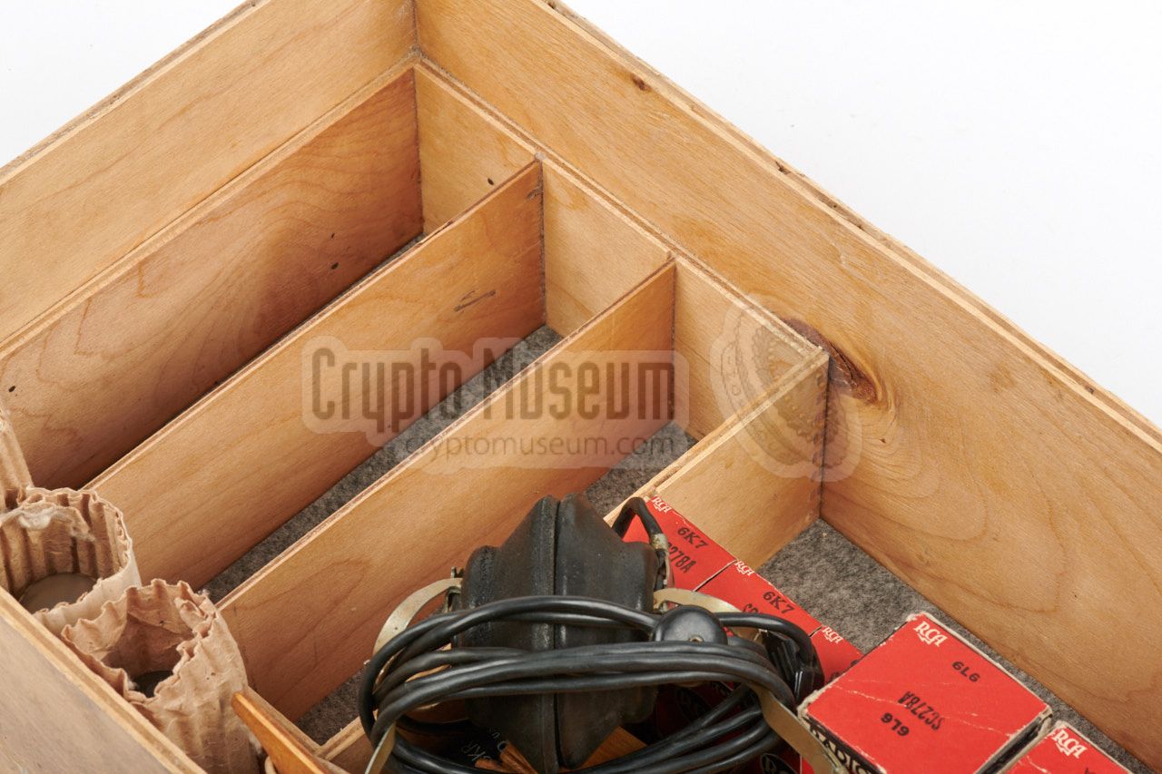
The storage box had clearly seen some action and, although it is
not a critical part of the set, the wood had dried out somewhat
and some panels had come loose.
Furthermore, the bottom padding had fully
desintegrated and was sticking to the parts inside the box. For these
reasons we decided to take the box partly apart, repair any cracks,
glue the parts back together and give the inside of the box an
invisible protective layer.
The padding was replaced by contemporary felt, in order to
protect the equipment, accessories and the spare parts when stored
inside the box.
|
|
|
|
The image above shows the restored box with the spare parts stored
inside, and the four units removed. When testing the radio, we
first connected it to the mains by means of a VARIAC, and gradually
raised the voltage from 50V to 230V in small increments,
over the course of an hour.
|
This was done to protect and rejuvenate the electrolytic capacitors
of the Filter Unit. Once the reformation cycle was over,
the transmitter and receiver were connected to the PSU and tested.
The transmitter worked straight away, both with and without a crystal.
It could easily be tuned to the connected wire antenna, using the
indicator lamps on the body of the transmitter. Next, the receiver
was tested. It worked straight away, but appeared to be insensitive.
Furthermore, it was impossible to correctly adjust the regeneration
control, resulting in interfering audio tones.
|
|
|
|
After measuring the HT voltage supplied to the receiver, it was
noticed that this was down at 70V, which is not enough to
properly drive the 6J7 valves, for which the nominal voltage should
be in the 100V range. After checking the 5Z4 rectifier valves on the PSU,
it turned out that one of them was not functioning properly.
After swapping it, the HT voltage increased to 97V and like magic
the receiver worked as expected. The Tensor featured on this page
is now fully operational again.
|
|
The PSU acts as the main hub that connects all units of the Tensor radio
station together. It has two custom power sockets for the receiver and the
transmitter, plus a fixed cable with the custom 6-pin plug at the end,
that connects to the filter unit. The pinout of each socket is given below.
|
- 0V (common)
- LT 6.3V AC
- HT1 low: +300V DC, high: 400V DC
- HT2 low: +500V DC, high: 650V DC
|
|
- 0V (common)
- LT 6.3V AC
- HT 97V DC
|
|
|
The filter unit is a rather strange device and should be considered
an integral part of the PSU. It passes the mains voltage (in our case
240V AC) to the PSU (via pins 4 and 5) and contains the electrolytic
capacitors for stabilisation of the various DC voltages of the PSU,
simply because they do not fit inside the PSU. The PSU generates two
high voltages: +300V and -300V, which are connected in series to
provide 600V for the transmitter. As a result, the transmitter and
receiver do not share the same 0V rail. Furthermore, one side of
the mains is connected to the virtual 0V.
|
- DC +97V
- DC +275V
- DC +325V
- 0V (common, virtual)
- AC 220V (mains)
- DC -318V
|
|
Power 13-30W (CW only) Frequency 3.7 - 14.3 MHz Ranges 4 ➤ see below Valves 6F6, 6L6 Size 17.5 x 10.5 x 4.6 cm (without valves) Weight 1000 grams (1106 grams with valves)
|
Red 3.7 - 5.2 MHz Black 5.2 - 7.2 MHz Green 7.2 - 10.2 MHz Yellow 10.2 - 14.3 MHz
|
Frequency 3.3 - 15 MHz Ranges 2 (automatically selected by dial) Valves 3 x 6J7 Size 17.5 x 10.5 x 4.6 cm (without valves) Weight 639 grams
|
AC mains 90, 100, 110, 125, 140, 180, 200, 220 and 240V Size 17.5 x 10.5 x 6.1 cm (without valves) Weight 3080 grams (with valves)
|
Size 17.5 x 10.5 x 4.5 cm (without valves) Weight 765 grams
|
-
Two or three rectifier valves, depending on model.
|
- 3 x Electrolytic capacitor 20µF.
- 5 x Light bulb 2V/75mA, E10 fitting
- 1 x Neon lamp
- 2 x Resistor 100 kΩ/2W
- 1 x Resistor 1 kΩ/1W
- 1 x Capacitor (?)
- 4 x Fuse 1A
- 4 x Fuse 2A
|
- Louis Meulstee, Wireless for the Warrior, volume 4
ISBN 0952063-36-0, September 2004
- Hauptamt Ordnungspolizei, Funkpeilung der Kurzen Wellen, 1. Teil
Berlin 1943. pp. 164-165.
- Austrian Signals Museum, Tensor in watertight metal cache container
Photographed July 2015.
- Military Historical Collection - Gausdal, Image of Tensor Mark 1
Website. Retrieved October 2017.
- User 'Luger', Russian spy radio 'Tensor'
War Relics Forum. Retrieved October 2016.
- Eric Kelley, Tensor transmission schedule 1742
USSR, 1939. Discovered 2007. Reproduced from film 2017.
- The National Archives, Description of radio sets used by NKVD
TNA KV2/2827-1, page 55.
|
|
|
|
Any links shown in red are currently unavailable.
If you like the information on this website, why not make a donation?
© Crypto Museum. Created: Sunday 15 October 2017. Last changed: Monday, 02 March 2026 - 12:55 CET.
|
 |

|
|
|


![Canvas carrying bag, issued with Tensor during WWII [2]](img/tensor_1942_full.jpg)


![Tensor receiver circuit diagram. Source: Wireless for the Warrior, Volume 4 [1].](svg/tensor_circuit_rx.svg)


