|
|
|
|
|

|
|
← SBO NL Germany SP-15 →
Dutch stay-behind version of the SP-15
The SP-15
was a complete self-contained modular
spy radio station, developed in Germany
in the early 1960s by Wandel & Goltermann and H. Pfitzner, for use by
the BND,
Special Forces (SF) and the German Stay-Behind Organisation (SBO).
In the late 1960s, the set was also introduced with the
Dutch Stay Behind Organisation O&I,
where it became known as the FSS-7 1
(also as FS-7).
|
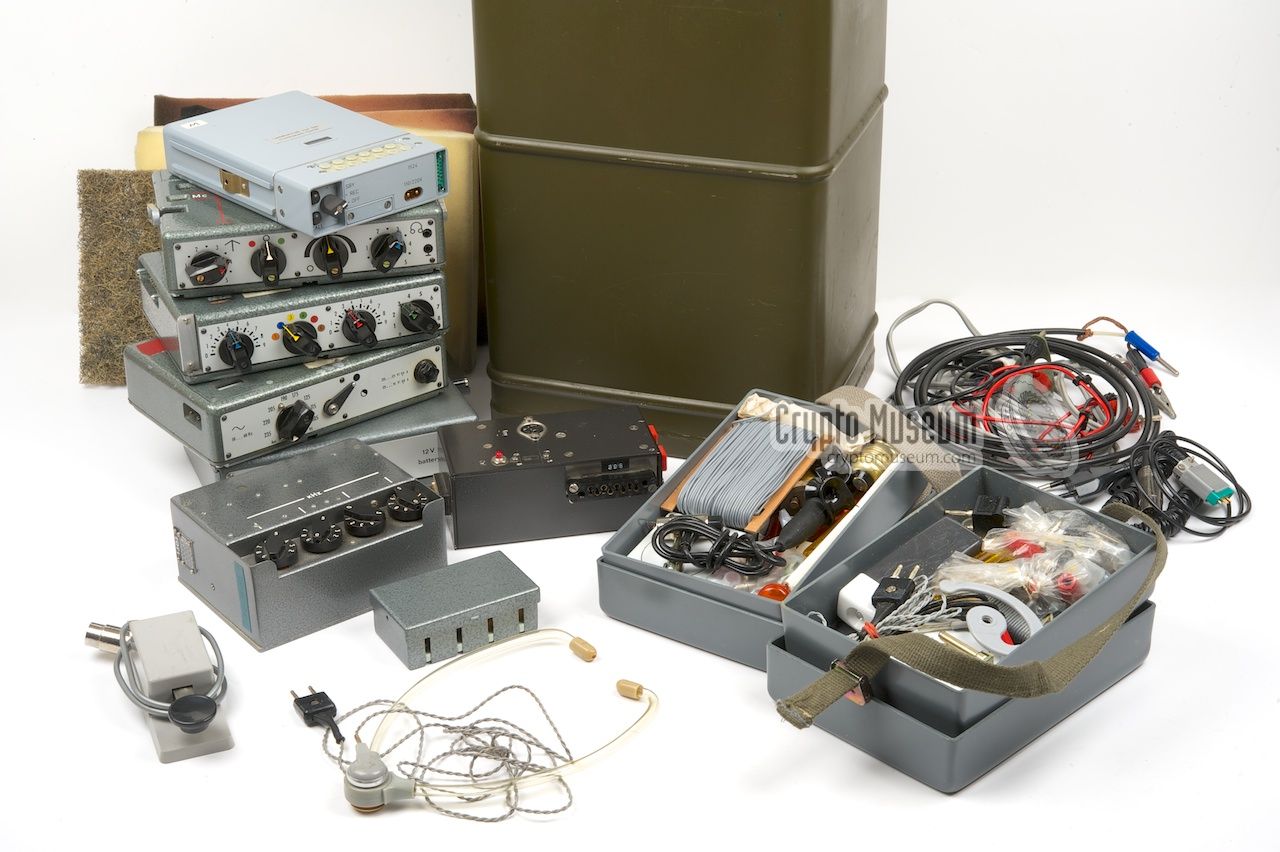
The set was supplied in a
green military watertight container
that was supplied by the Dutch Army, and contained an
FS-7 transmitter, an
FE-8 receiver,
a mains AC power supply unit (PSU)
and a DC battery PSU.
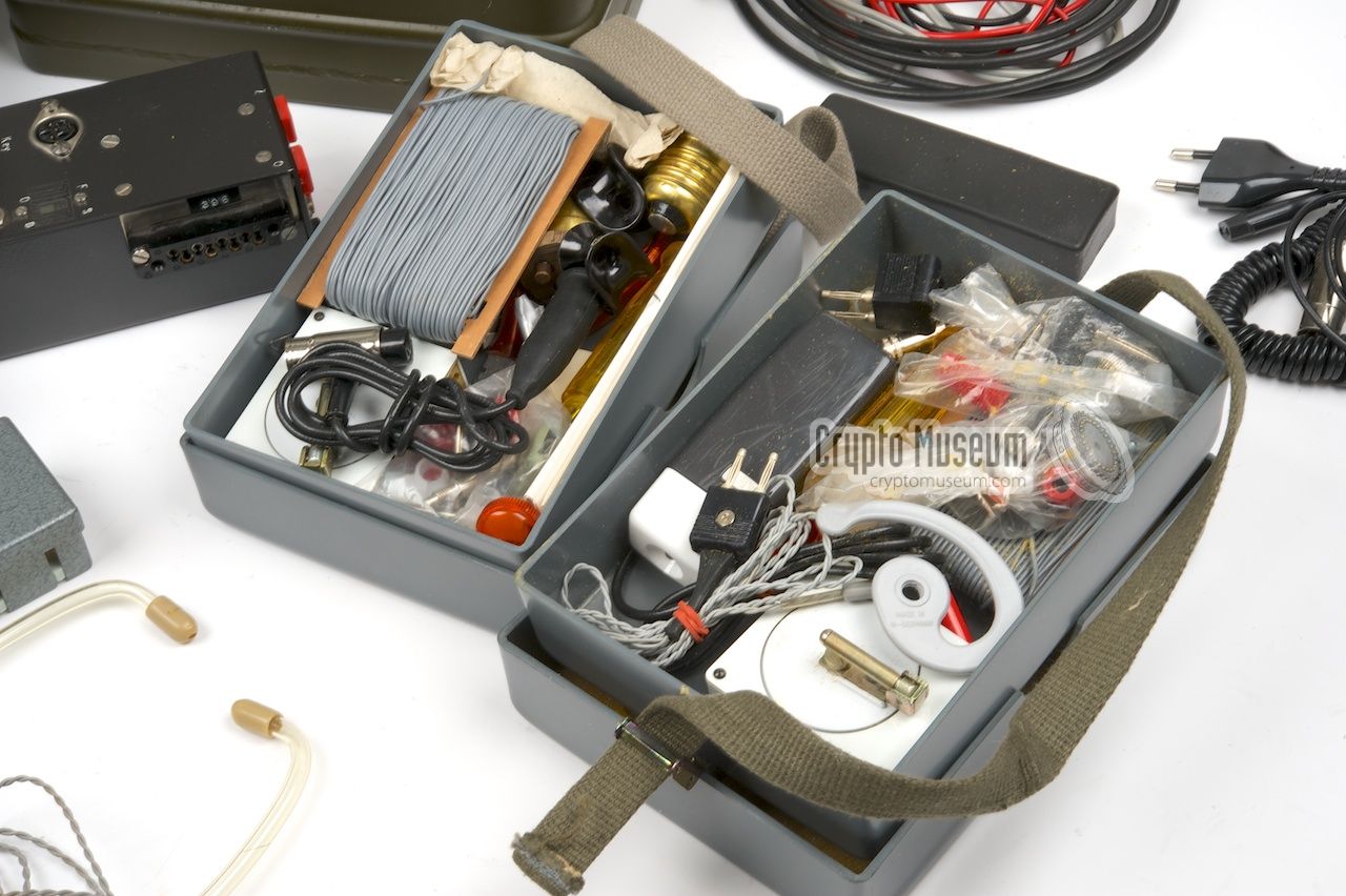
The accessories,
like the wire antennas, connectors, lamp fittings,
morse key, headphones, isolators, tools, cables, etc.,
were supplied in two grey plastic lunch boxes.
Initially, the transmitter was crystal operated and a suitable set of
crystals was supplied in a small metal container. The FE-8 receiver had
a built-in VFO and was suitable for all SW frequencies.
|
|
|
|
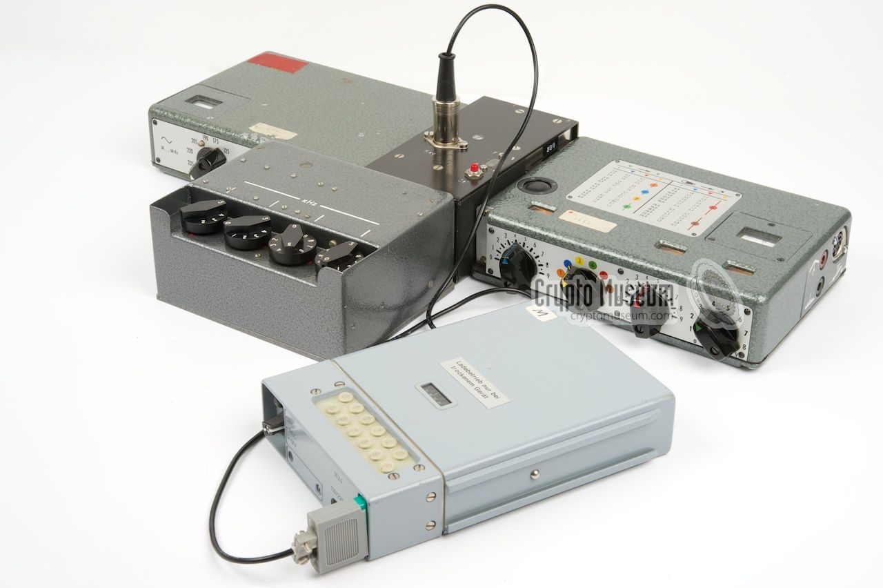
Around 1975, by which time the Germans had already swapped their
SP-15 sets
for the newer SP-20,
the FSS-7 was given a mid-live upgrade by the addition
of a purpose built synthesizer.
This required modifications to all
FS-7 transmitters
and the addition of an extra junction box.
|
This junction box acted as an interface that connected all parts of the
transmission chain together. It was made by the Dutch themselves and
contains additional circuitry for calibrating the receiver, switching the
antenna between transmitter and receiver, powering the Racal synthesizer
and performing FSK modulation.
FSK, or Frequency Shift Keying, was necessary to support the much higher
speed of a new burst encoder that was also part of the set.
The image on the right shows the upgraded FSS-7 set 2 including
synthesizer, junction box and key.
|
|
|
-
In the Netherlands the SP-15 was named after the FS-7 transmitter
(Funk-Sender), but it was also known as FSS-7 (Funk-Sender-Synthesizer).
Some (internal) literature refers it as FFS-7 (Feld-Funk-Sender).
-
The FSS-7 set shown here is from the collection of Museum Jan Corver
in The Netherlands. Many thanks for allowing us to take detailed pictures
of this special version of the SP-15 and its container.
|
The Dutch Stay Behind Organisation
Like most other Europeans countries during the
Cold War, The Netherlands
had its own Stay-Behind Organisation (SBO),
a secret army that would be
activated in the event of an invasion by the Soviet Union.
The Dutch SBO was established in 1946 or 1947, just after WWII had ended,
and became known as O&I (later: A&B). After much debate, the
organisation was dismantled in 1992.
|
During the initial years, O&I used its own
ZO-47 radio sets, develop by
Dutch electronics giant Philips, but once the
North Atlantic Treaty Organization (NATO)
was established in 1949, newly developed
American radio sets
were used instead, such as the RS-1
and later the RS-6.
Around 1968, it was decided to replace the American radios by the SP-15
radio set, that had been in use by German organisations since the early
1960s. As the Dutch operated in small unlinked cells, each cell was
given its own radio set and radio operators were trained on its use.
|
|
|
Each radio operator was given two watertight metal containers like the one
shown above. One was filled with money, juwelry, a pistol and ammunition.
The other one contained the radio set. The containers were generally stored
in the attic or burried in the garden on in a secret cache and were only
retrieved for test, trainings and, of course, in the event of a war. After a
series of incidents, both nationally and internationally, the secret network
became known to the public which led to public debates and investigations.
As by that time the Berlin Wall had come down and the
Soviet Union had
collapsed, the Dutch government dismantled the organisation in 1992.
➤ More about O&I
|
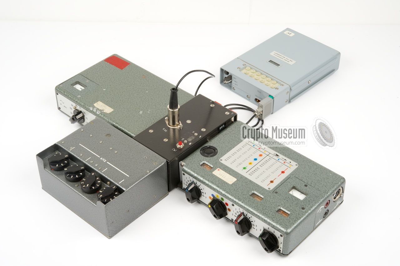
The diagram below shows the complete FSS-7 transmission chain.
The FE-8 receiver is not shown here. The transmitter and the PSU, that are
normally connected to each other, are separated and the new junction box
is placed inbetween them. The new synthesizer is attached to the front
of the junction box and a high-speed burst encoder is connected to the DIN
socket at the top.
Note that both the RX and TX antenna connections are routed via the new
junction box as well, so that from now on only one antenna is needed.
Switching between RX and TX antenna is done automatically by the circuitry
inside the junction box. It also contains a calibrator for the receiver.
|
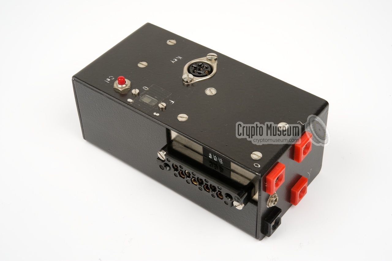
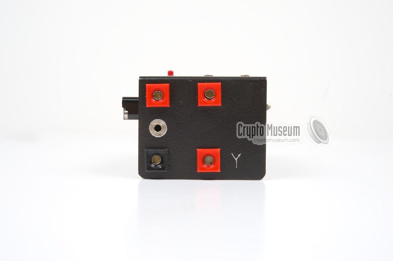
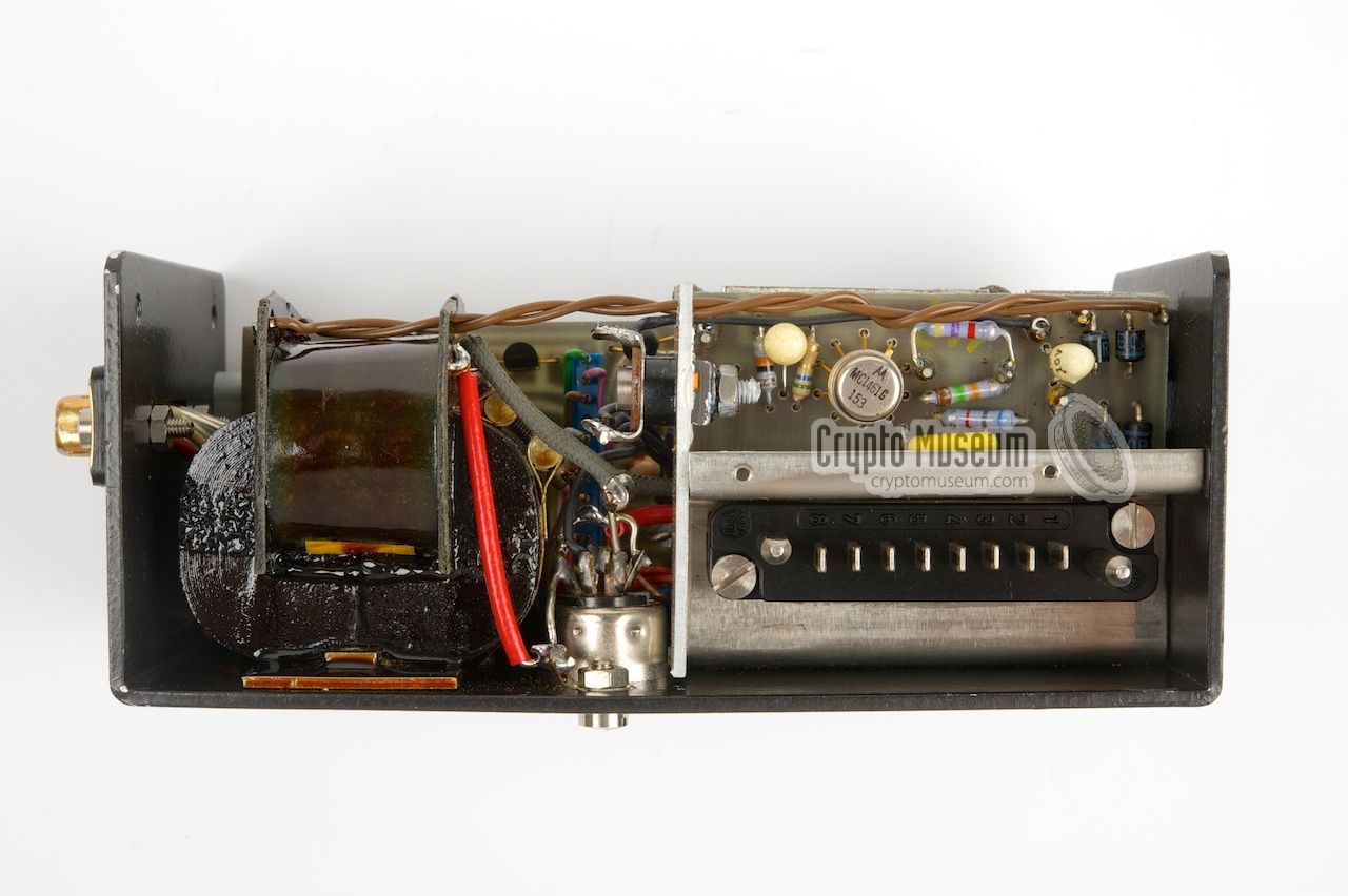
The FS-7 transmitter was developed by Pfitzner in Germany and is
built around two valves (EL95 and EL81) and just one transistor (OC450).
Around 1975 it was modified for use in combination with the new Racal
synthesizer. As a result, the crystal socket at the far left of the front
panel was removed.
➤ More information
|
|
|
The FE-8 receiver was developed by Wandel & Golterman (W&G) in
Germany in 1958 and can be used stand-alone. It can be powered by an
internal battery or by an external DC source.
The receiver has two ranges (2-5.1 MHz and 5.1-9 MHz) with permeability
tuning, resulting in a linear scale for both ranges. This receiver
was also used with the later SP-20 radio sets.
➤ More information
|
|
|
The FSS-7 was supplied with a highly compact mains power supply unit (PSU)
that was suitable for all common AC mains voltages in the world, between
95 and 235 V. It produces the LT and HT voltages for the transmitter.
It is normally slotted into the left side of the transmitter or, in the case
of the modified Dutch FSS-7, into the left side of the junction box.
|
|
|
When no mains AC network was available, it was also possible to power
the FSS-7 from a 12V DC source, such as the battery of a car. This was done
by swapping the AC PSU for a DC one.
It contains a power inverter that converts the 12V DC input into 6.3V
for the filaments and a HT AC voltage for the transmitter's valves.
Like the AC PSU, it is slotted into the left side of the transmitter or
the junction box.
|
|
|
|
Around 1974, the German SBO swapped their SP-15
units after 15 years of service for the newer SP-20
with had a synthesizer-driven transmitter.
Although The Netherlands desperately wanted to switch form crystal-based
operation to synthesizers, their sets were just 6 years old,
making a transition to the newer sets not economically justifiable,
and another solution had to be found.
|
It was decided to give the FSS-7 a mid-live upgrade by adding
an external synthesizer to the transmitter. A suitable one was
subsequently developed by Racal
(UK) and 160 units were ordered
for a total price of
NLG 2 million. 1
A budget for the development and manufacture of the units was arranged
and the sythesizers were delivered by Racal during the following year.
A typical unit is shown in the image on the right. Is has four rotary
selectors for setting the frequency in a recessed bay at the top front,
and a single 9-pin male sub-D connector at the rear.
|
|
|
All voltages and HF signals are guided to and from the synthesizer via
this connector. The device is higher than the other modules
and has a typical Racal-look. In order to use it with the FS-7
transmitter, the latter had to be modified and a special
junction box
had to be fitted inbetween.
|
Taking away the bottom panel of the synthesizer reveals a rather
complex structure
of metal cans of varying sizes and a lot of wiring to connect
it all together. Although this Racal unit definitely would not have won the
prize for most beautiful design,
it reflects the state of technology in
1974, when synthesizers were just beginning to find application in
professional equipment.
All in all, the Racal synthesizer proved to be a very reliable addition
to the radio set and greatly improved the overall flexibility of the set
as it eliminated the limitations of the old crystals.
|
|
|
Once connected to the set, the four rotary selectors on top of the device
are used for setting the transmission frequency. The leftmost knob can
be set from 2-8 MHz. The other three knobs have the full 0-9 range.
This means that frequencies can be generated from 2.000 MHz to 8.999 MHz.
|
-
This means that each synthesizer had a price tag of NLG 12,500
(EUR 5680) in 1975.
|
|
When the Racal synthesizer was added to the FSS-7,
the transmitter had to be modified as it would no longer be used
directly with crystals. Furthermore, the signal from
the synthesizer had to be fed to the oscillator stage of the
transmitter and the synthesizer itself had to be powered.
|
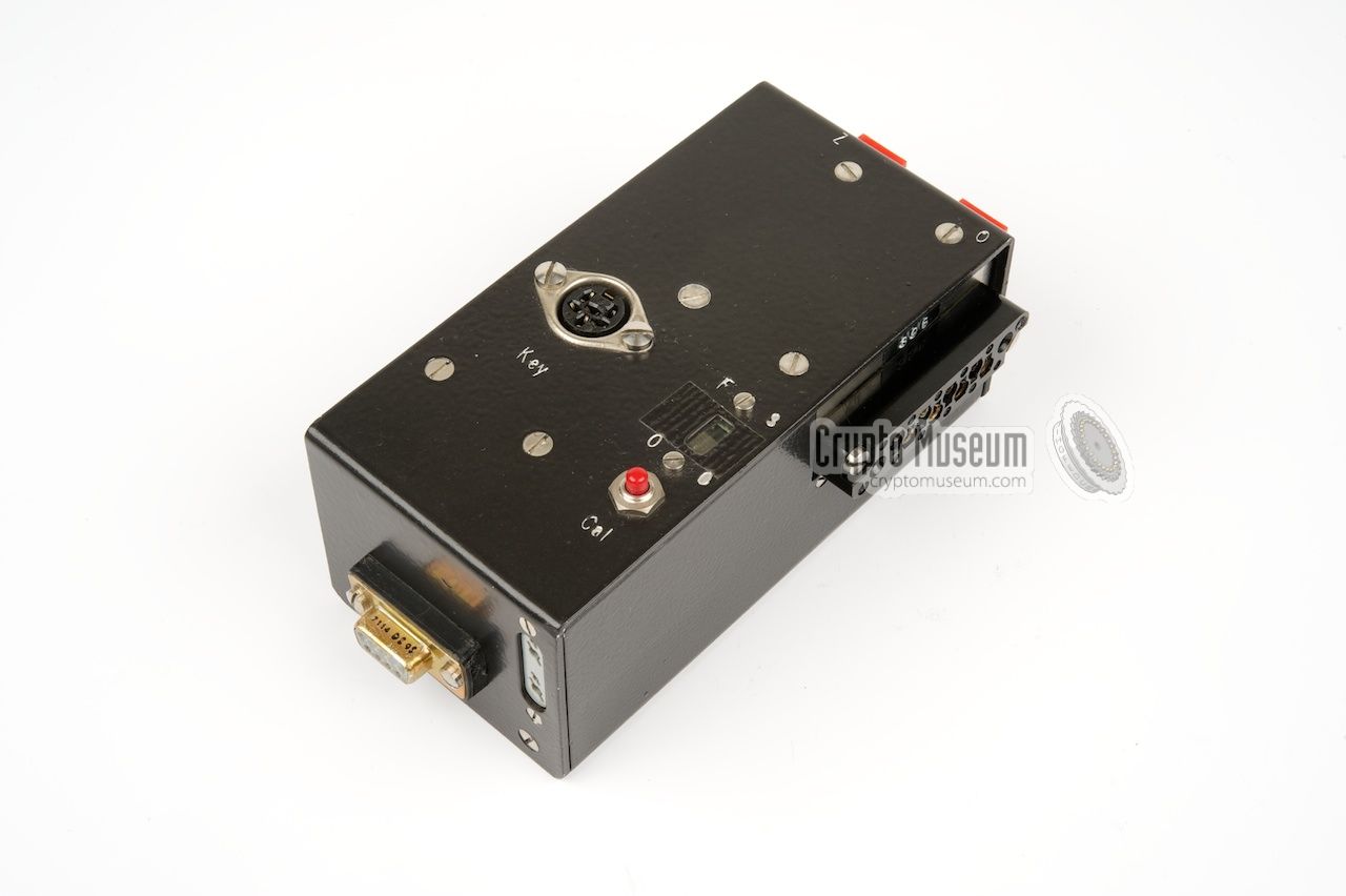
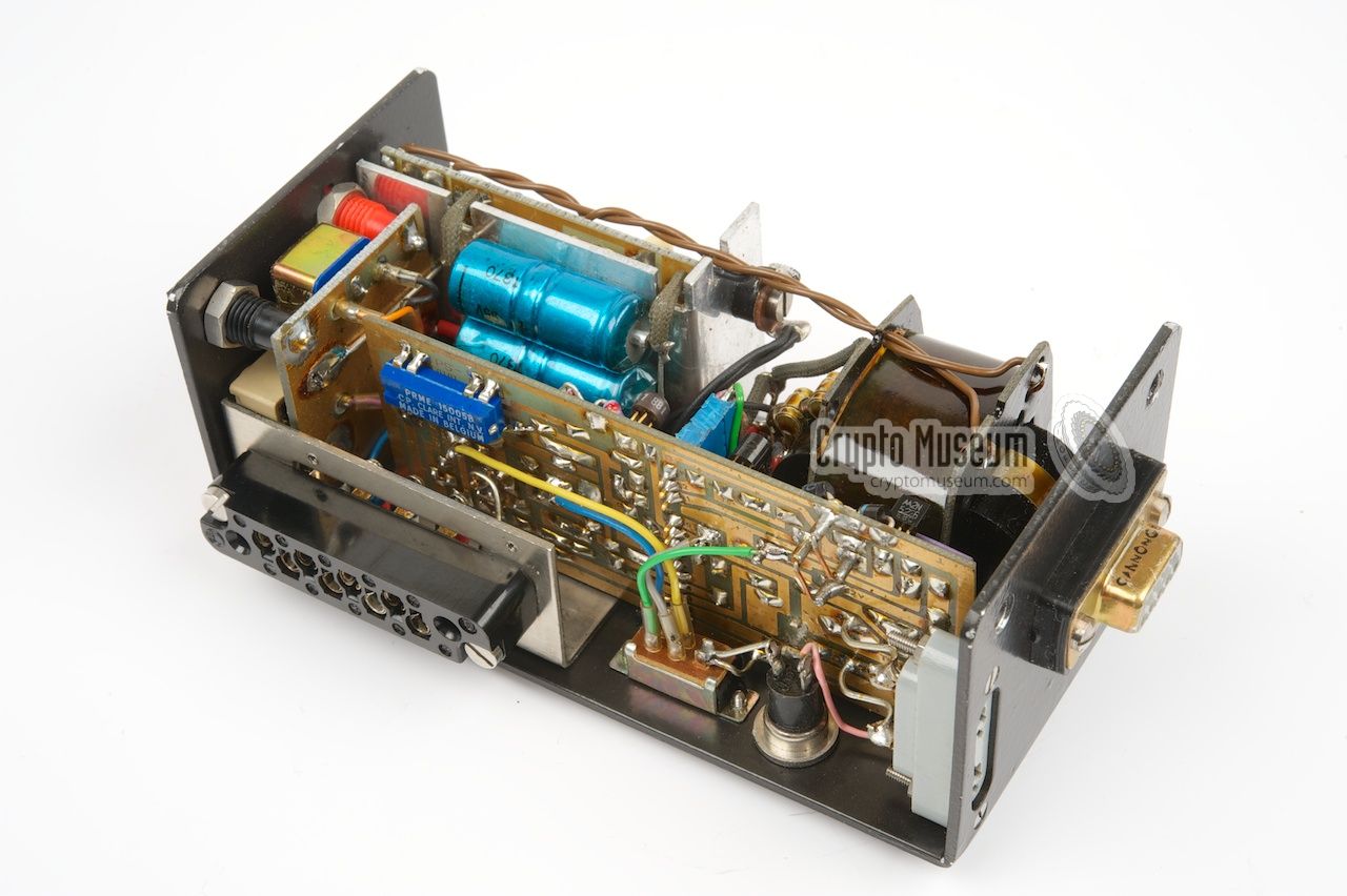
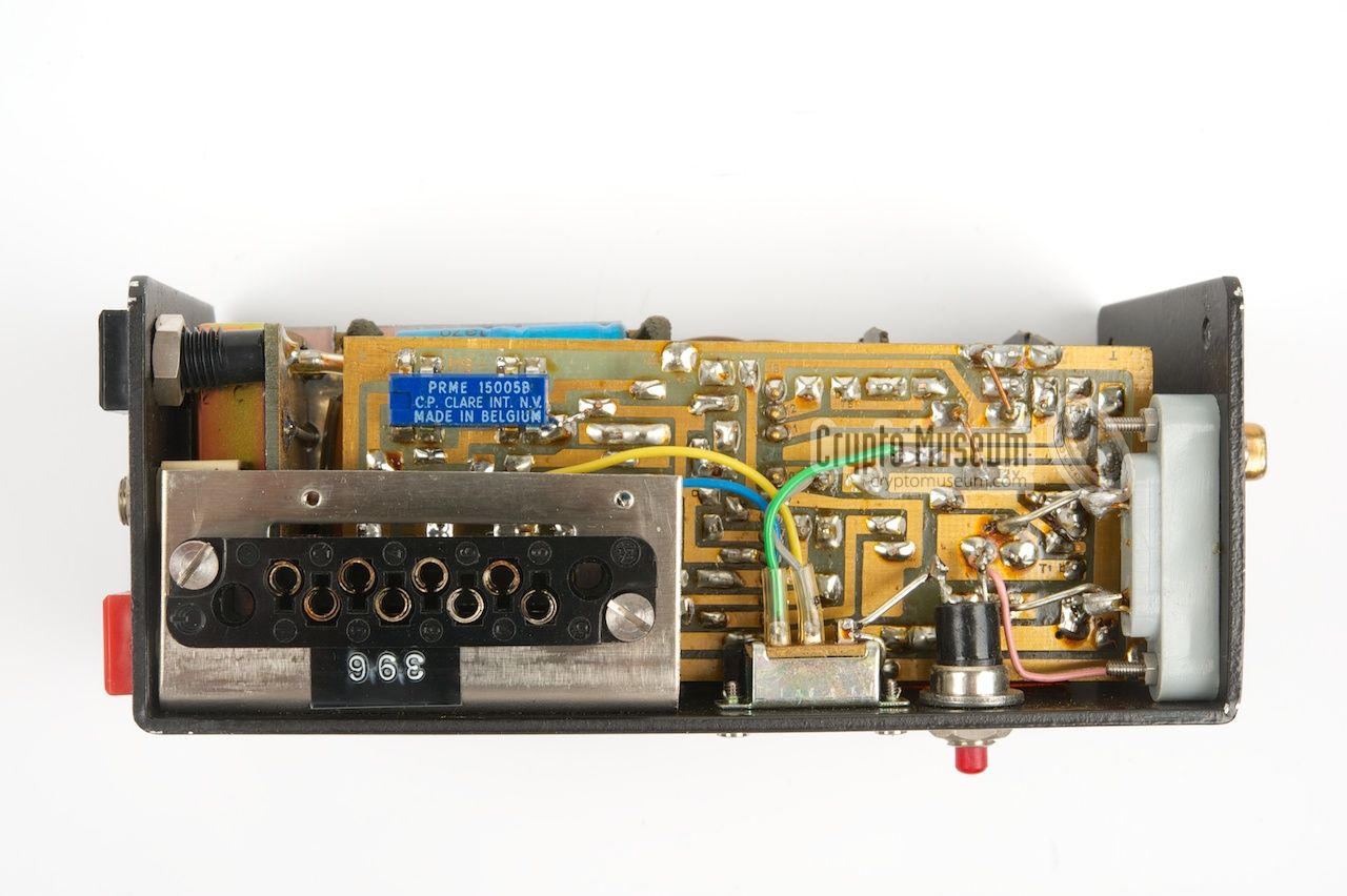
In order to fit all units together in the upgraded set, a special
junction box or common interface was built by the
technical department of O&I. It consists of a small rectangular
metal box with connectors on all sides. It is fitted in between
the transmitter and the PSU. The synthesizer is connected
to the sub-D connector at the front.
The FS-7 transmitter is modified and can no longer be used
stand-alone. The crystal socket at the front left is
removed
and its lines are now routed via the large
connector at its left side, where the new junction box is now
connected.
|
|
|
The signal from the synthesizer is fed to the transmitter via the
junction box. For emergency purpuses, e.g. when the synthesizer is
broken, it is still possible to use crystals, by inserting them into
the socket at the front of the junction box.
For this the synthesizer has to be removed.
|
On top of the junction box is a 6-pin 270° female DIN socket, for
connection of the burst encoder or, in case the burst encoder is
broken or can't be used, the small standard morse key.
Towards the front right is a small red push button that can be
pressed to activate the built-in reference oscillator that is used
for calibrating the receiver, much like the
separate calibrator
does with the standard version of the SP-15.
Just behind the CAL button is a 2-position slide switch marked FS/OO.
It is currently fixed to OO.
The function of this switch is currently unknown.
|
|
|
The junction box also handles automatic switching of the antenna
between transmitter and receiver, a feature that is missing from the
standard SP-15 set which requires separate send and receive antennas.
The antenna connections
are at the rear, close to the internal antenna relay.
|
In addition to all of this, the junction box also contains a
small PSU for the synthesizer which needs its own stabilized
power source. It works by taking the HT voltage from the main
PSU to the FS-7, and feeding it to a small transformer.
The image on the right shows the interior of the junction box
as seen from the rear right. At the bottom right is the long
conector that is fitted to the socket at the left side of the
transmitter. At the left is the transformer of the synthesizer's
PSU. It also powers the electronic circuits inside the junction
box. The stabilizer is at the right.
|
|
|
The junction box contains a modulator for Frequency Shift Keying,
or FSK, which is needed to support the much higher data rate of
the Speicher burst encoder. At the rear of the junction box, between
the antenna sockets, is a 3.5 mm jack socket that provides the
side tone from the keyer. It should be connected to the
side-tone input of the receiver and is used to monitor the sound.
Although the junction box may seem like a simple device at first,
it implements the following:
|
- Antenna switcher
- Interface between synthesizer and transmitter
- Frequency Shift Keying (FSK) modulator
- Crystal oscillator
- Side-tone generator
- Calibrator
- PSU for synthesizer and circuitry
|
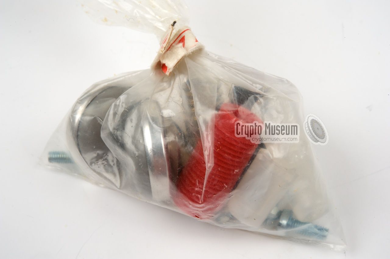
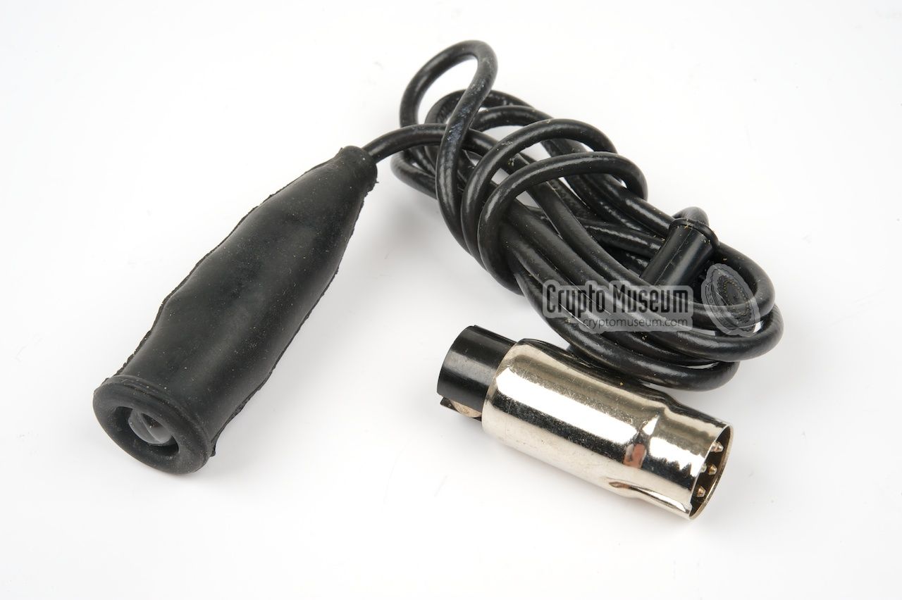
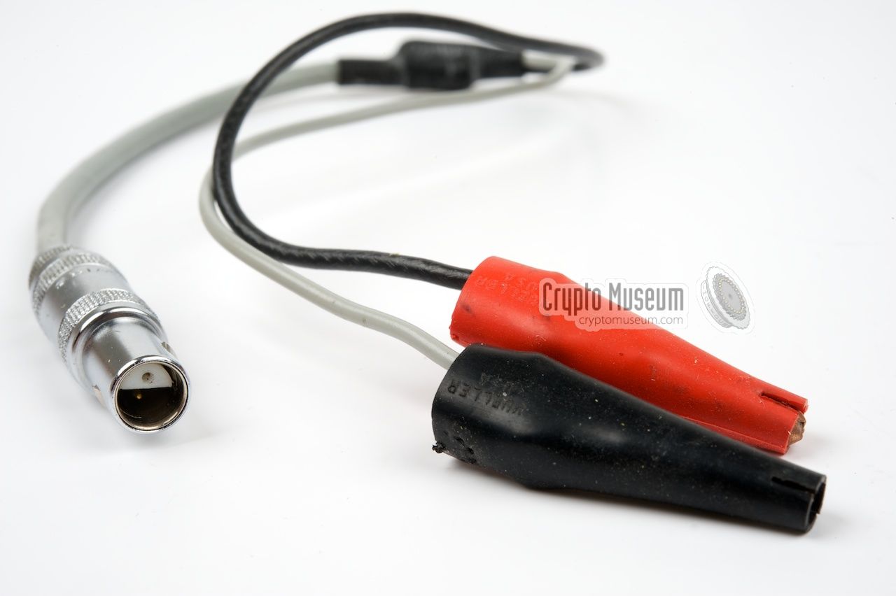
Like most spy radio sets of the era, the FSS-7 (SP-15) was supplied with
a wide range of accessories, many of which were used to rig up the set
under improvised conditions. There are various types of mains plugs
and even adapters for 'stealing' power from a lamp fitting.
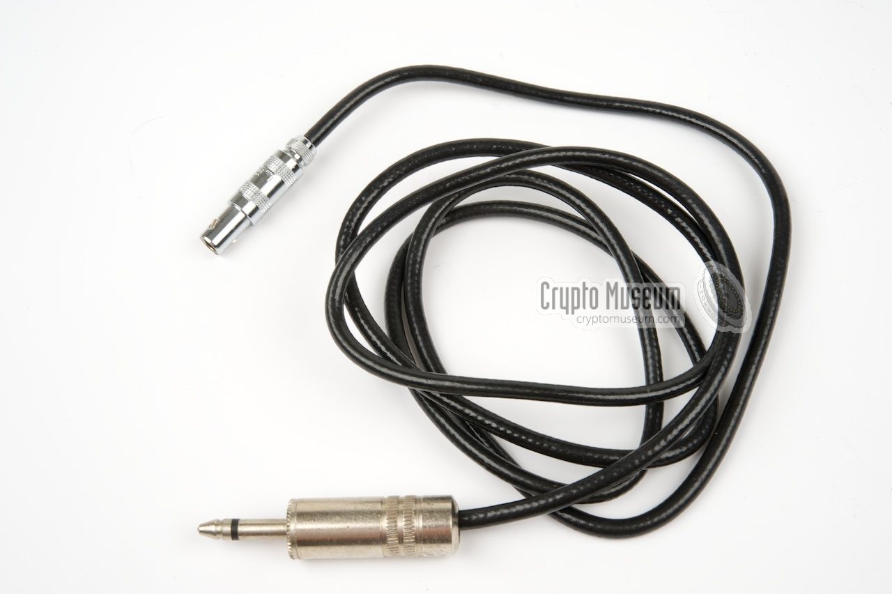
In addition there are the standard accessories, such as the antenna wires,
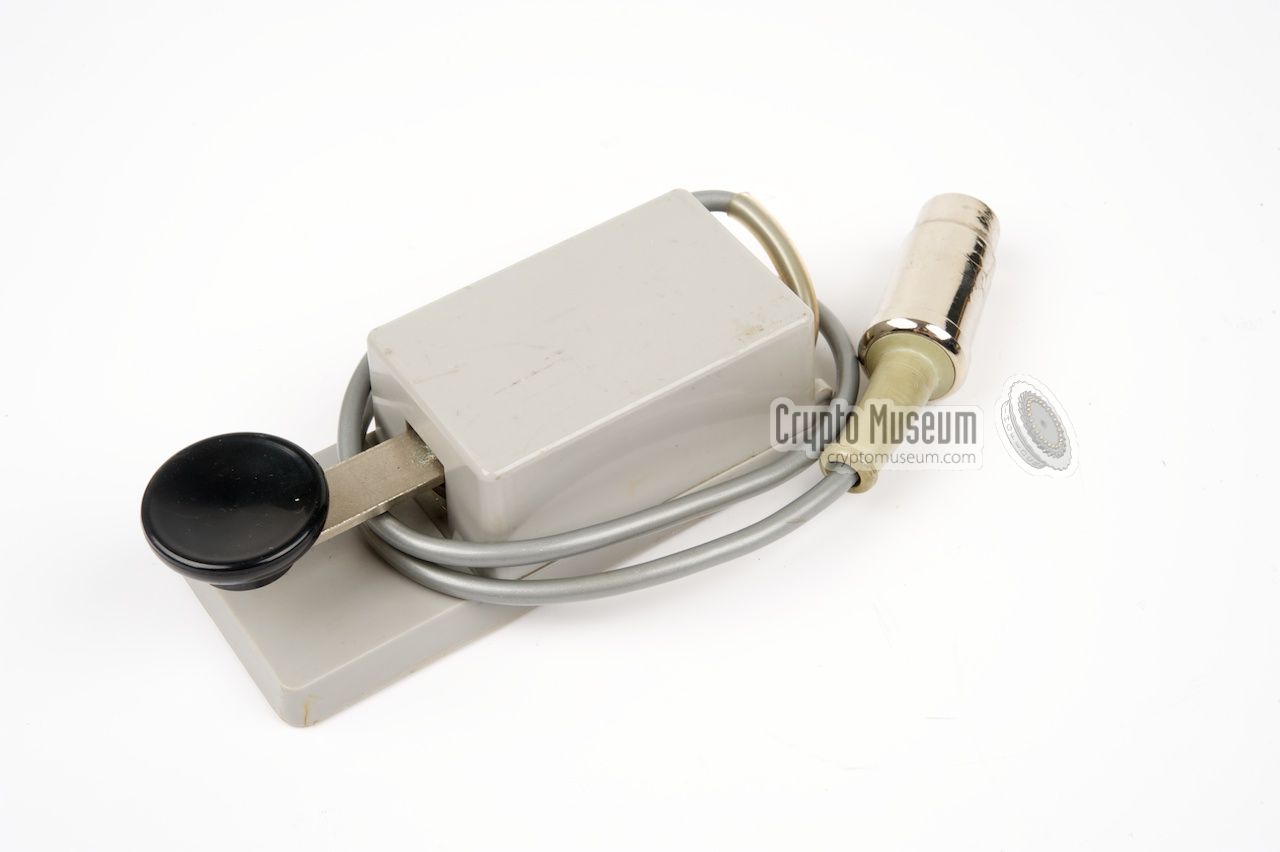
counterpoise, wind-up antennas, morse key, earpieces, isolators, tools
and even a small pocket lamp. Examples of some of the accessories in the
images below.
|
|
|
|
In the early days of the SBOs, radio messages were sent by means of
morse code, for which operators had to be
trained especially. The downside of using manual morse code is the fact
that the transmitter is on the air for long periods of time, especially
when sending long messages, giving the enemy a chance to locate the
station by means of Radio Direction Finding,
or RDF.
|
With the arrival of the first American radio sets,
like the RS-1,
the use of high-speed burst encoders
was introduced. These devices
allowed a message to be pre-recorded on some kind of medium,
and then sent via a transmitter at very high speed. This reduced the
on air time and, hence, the chance of detection and interception.
In the early days of the FSS-7 the old American
GRA-71 burst encoder
was used, as supplied with the RS-1
and RS-6 sets,
but they were soon replaced by the newly developed fully electronic
German Speicher
(Memory) that is shown here.
|
|
|
The Speicher was initially connected directly to the morse key DIN
socket on the transmitter,
but later (after the introduction of the synthesizer)
to the black junction box at the centre.
It required a text-based message to be converted into numbers
first, using some kind of manual encoding scheme. The numbers were then
entered into the device in groups of five, separated by spaces.
|
Once the message was complete,
the transmitter was powered up and Speicher was set to PLAY,
after which the entire message was sent in just a few seconds,
with far less risk of being captured.
Around 1973/1974, some (but not all) Speicher units were replaced by
the more advanced MMP that is shown in the image on the right.
It is suitable for alphanumerical messages.
The MMP was not supplied with the FSS-7 set shown here.
➤ More about the Speicher
➤ More about the MMP
➤ More about GRA-71
|
|
|
|
Below is the pinout of the 6-pin 270° DIN socket on the IF-7 interface.
Although this socket is compatible with the 5-pin DIN socket on the
FS-7 transmitter, it carries voltages that are not available on the
transmitter socket. The morse key or burst transmitter should be connected
to this socket, rather than to the transmitter. When using the
GRA-71 burst encoder,
the keyer is powered by the -12V DC voltage on the socket.
|
- Not connected
- KEY
- Ground
- (-)12V DC
- 6V AC
- Unknown (brown wire from synthesizer DE9 socket)
|
|
|
|
|
Any links shown in red are currently unavailable.
If you like the information on this website, why not make a donation?
© Crypto Museum. Created: Saturday 19 September 2015. Last changed: Wednesday, 23 September 2020 - 23:04 CET.
|
 |

|
|
|