|
|
|
|
|

|
|
Belgium SDRA-8 MBLE Paraset
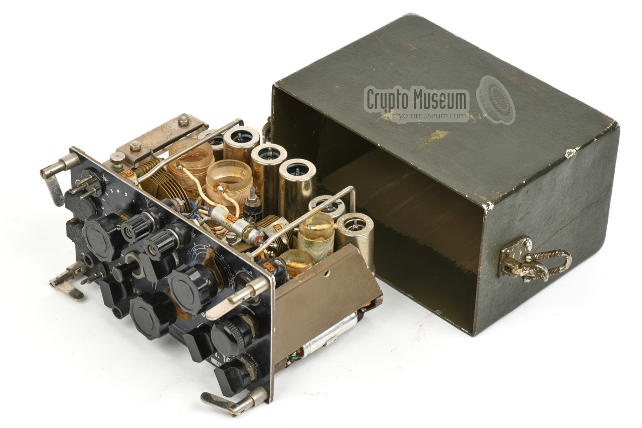
The RST-101 is a combined transmitter-receiver, or transceiver,
that measures just 18 x 13 x 9.5 cm and weighs 1800 grams.
It just requires an external
power source, an antenna, a suitable counterpoise, a morse key and
headphones. The receiver is free-running and the crystal-operated
transmitter provides six pre-defined channels.
In its most complete configuration, the radio set consisted of four
green canvas bags that contain the transceiver,
a hand generator, wire antenna, antenna mast
and accessories.
The bags could be strapped together and carried as a backpack.
|
|
|
The Belgian Special Forces Coy d'Equipes
Speciales de Reconnaissance (ESR), 2 used the device until the mid-1980s.
It has provisions for using 12 pre-determined transmission channels,
6 of which were user-selectable from the front panel. Swapping the crystals
requires the device to be opened as it does not have an external
crystal socket.
Although this was clearly a disadvantage of the small transceiver,
it was probably considered sufficient for behind-enemy-lines operations.
The transmitter is powered by a (supplied) hand-driven generator.
The receiver can be powered by the same generator, but also
by a separate combined battery (6V, 150V). The morse keys
and headphones
were all sourced from WWII surplus of the Third Reich (Germany).
The set is similar to certain to WWII radio sets. The circuit resembles
that of the British Mark VII (Paraset),
and the hand-generator is merely a copy of the
Type 45/III that was supplied with the Jedburgh Sets.
|
 |
-
In the manual it is called Paraset.
Not to be confused with the British WWII
Mark V and Mark VII 'Parasets'.
-
Since the early 1980s: Long Range Reconnaissance Patrol (LRRP).
|
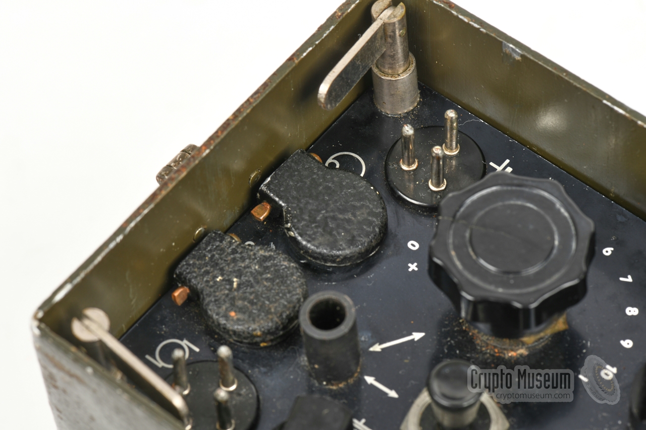
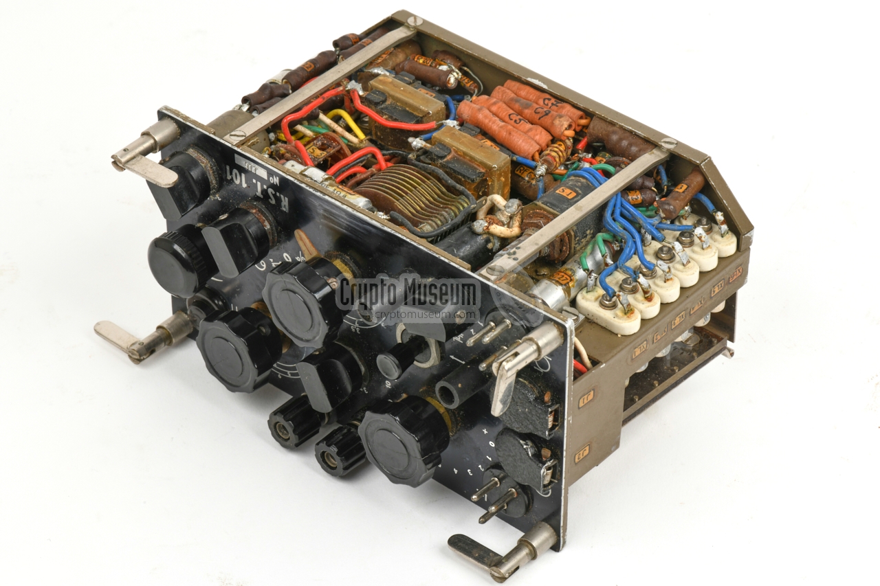
All controls and connections are located at the front panel,
which is shown in the diagram below. Most connections are at the left.
From top to bottom:
a 3-pin receptacle for connection of the battery pack,
a jack socket for the headphones, a jack socket for the
external morse key, and a 4-pin receptacle for connection of the
hand-operated power generator.
A long wire antenna and a suitable counterpoise (ground) should be
connected to the two banana sockets at the top centre.
The leftmost 2/3rd of the front panel is occupied by the transmitter.
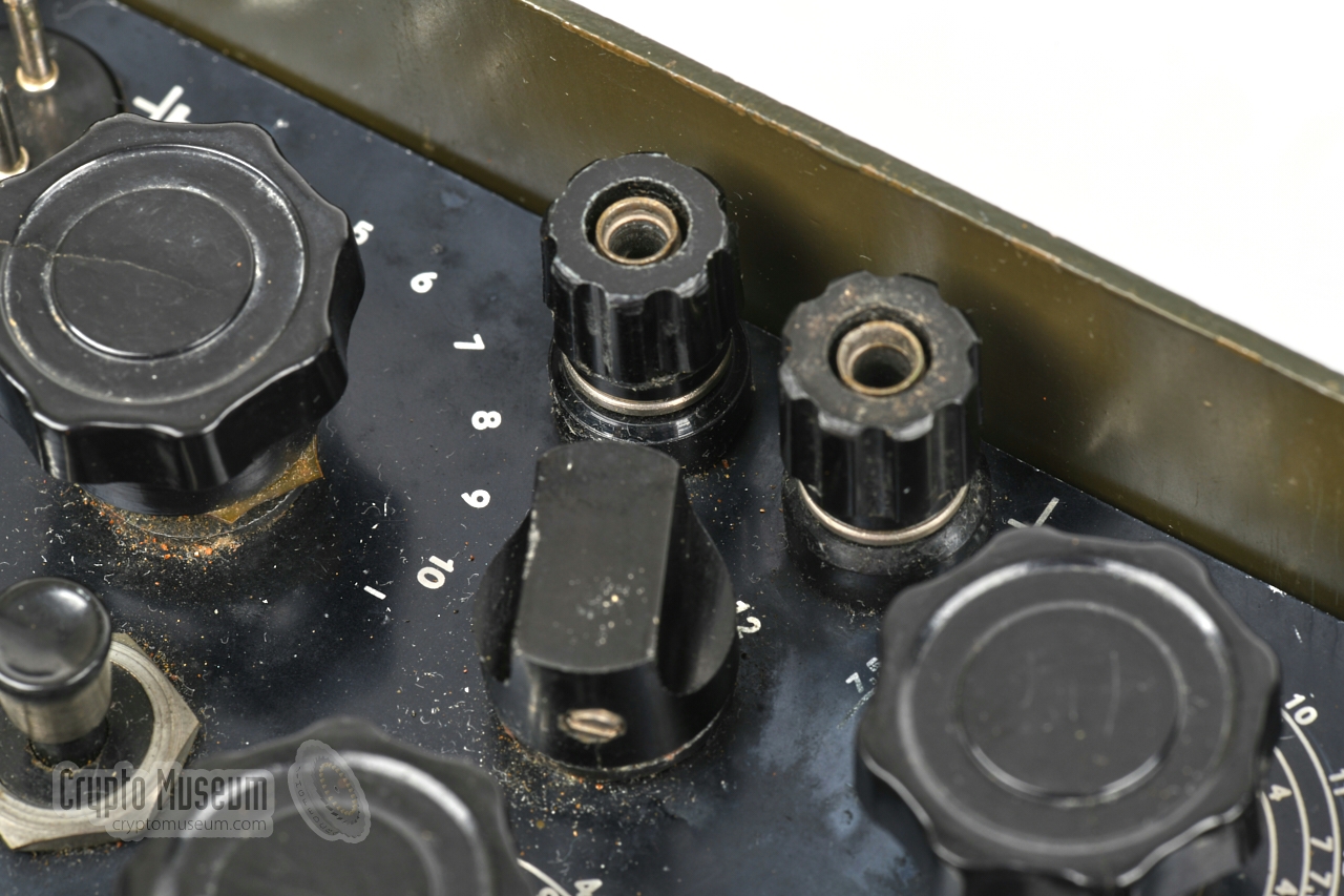
At the bottom left is a six-position rotary switch
for selection of the desired (crystal-based) transmission frequency.
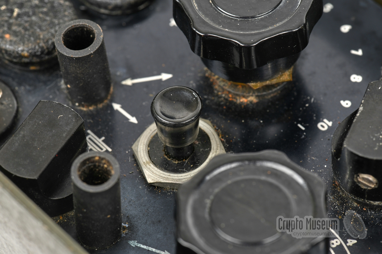
There are tuning knobs and light bulbs — embedded under a
piece of rubber hose — to maximise the output power.
The rightmost 1/3rd of the front panel holds the controls of the
receiver, with the exception of the
internal morse key which is located
at the top right. It was only used for testing.
|
|
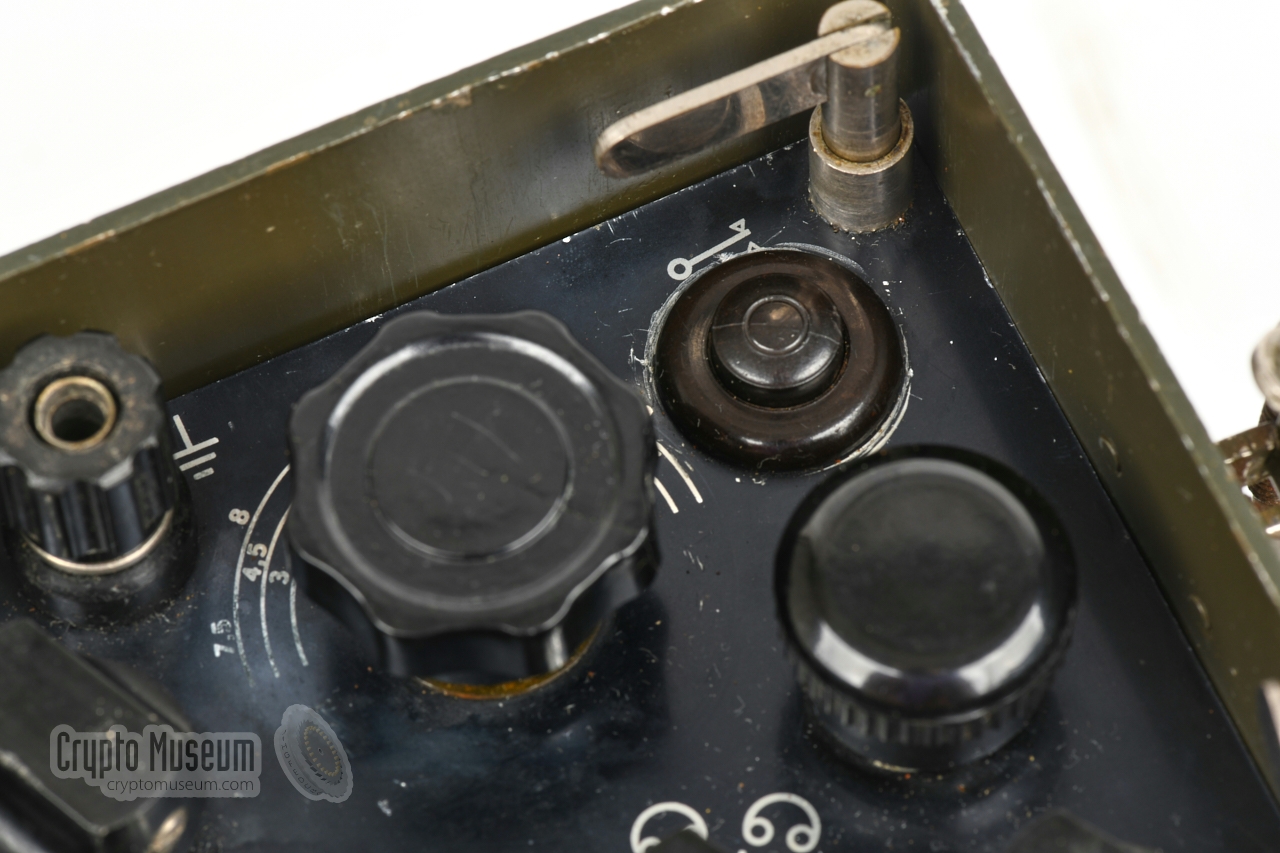
The MODE selector is located on the right half of the front panel,
just above the radio's name R.S.T. 101. It has the following four
settings, from left to right:
|
- OFF
- Transmit, powered by generator
- Receive, powered by battery
- Receive, powered by generator
|
Memoires of an ESR patrol member [5]
The RST-101 was developed by MBLE – a subsidary of
Philips
– around 1958, and was clearly based
on wartime radio sets, like the
British Paraset (Mark VII).
According to a former Belgian Special Forces member,
it was used by the 1st Coy d'Equipes Speciales de Reconnaissance (ESR),
the Belgian post-war equivalent of the
British Special Operations Executive (SOE).
In case of a war with the Eastern Block, the RST-101 would be used
for long-range patrols to be inserted behind enemy lines,
or for deep underground use when run over by the Warsaw Pact or
Soviet troups.
The set was designed to withstand high altitude drops, and was usually
tucked away inside the radio man's bergen (backpack). It was also used
during weeks of long deep penetrations and evasion marches. According
to the former ESR member, the radio set was extremely tough. On one
occasion it even survived in a bergen that was accidentally free-dropped
from high altitude. With the right maintenance and a bit of care,
it would work reliably for years without repairs.
The RST-101 is extremely small for the era. The batteries, of which
each patrol member would carry two or three, were bigger than the set.
Fortunately they were less heavy than they looked.
On important and long missions, battery re-supply drops were organised,
usually in the middle of a forest with a jungle line. On all missions,
one team member would carry the hand-operated power generator,
whilst one of his colleagues carried the small tripod stool.
All four members of a squad, were trained to operate the RST-101, and
had to be capable of taking messages in
morse code
at a minimum of 16 words per minute.
The former ESR member also remembers that the morse keys
and the headphones came from German wartime surplus.
Some of them still had the Nazi Eagle with Swastika embossed
or stamped on their cases.
Tuning in to a desired frequency for the reception of a broadcast,
was a nightmare. It was difficult to find the right channel
through tons of other emissions and static interference,
with the large bakelite knob and the inaccurate scale. Over time,
operators developed various tricks to make best use of the set.
Sometimes reception was lost, and could only be resumed by swapping
the antenna and ground wires. On other occasions placing a hand on
the case, improved reception.
The antenna was the biggest nightmare. It was horizontal
and had to be adapted for the desired wavelength by means of banana
plugs at strategic points along the wire. It was usually 16 to 22
metres long and was therefore difficult to hide.
The transmitter was specified to produce 5 to 8 Watts, which would
be sufficient for a rear base distance of 800 km. During tranings on
Corsica however, it was frequently possible to establish contact
with the main base in Belgium.
The RST-101 was used by the ESR until the mid-1980s.
In 1982, the Belgian Army started experimenting with more modern
equipment from other manufacturers, which was often 20 kg or more
heavier than the RST-101, but had the advantage of
high-speed burst transmissions.
Since the early 1990s, the ESR is known as the
Longe Range Reconnaissance Patrol (LRRP).
|
|
Below is a full description of the complete RST-101 kit, as it was
supplied to the Belgian paratroopers. The equipment is packed in four
canvas bags that can be strapped together to form a backpack. Power was
provided by a manually operated generator that was part of the kit.
|
The complete RST-101 set, including antenna and all accessories,
was supplied in four green canvas bags that could be strapped
together as shown in the image on the right. It could then be
carried during a patrol like a backpack.
The upper bag at the centre holds the radio and it accessories.
The lower one holds the power generator. The two tall bags at the sides
hold the antenna mast and the tripod for the generator.
|
|
|
The radio and its accessories can be stowed in the canvas bag shown in
the image on the right. It consists of two compartments, each with its
own cover. The compartment at the front holds the RST-101 radio.
The compartment at the rear offers space for the antenna wires, the power cables,
the headset, the morse key, the optional battery and the toolbox.
The canvas bag can be used as part of the backpack, but can
also be used separately, carried from the shoulder.
|
|
|
The RST-101 came with the water-resistant morse key shown in the image
on the right. This is basically a standard American morse key with a
rubber cover to protect it against rain.
The key is mounted on a pertinax plate. It has a fixed cable,
terminated with a 6 mm jack plug that mates with the jack socket at the
front panel of the RST-101.
|
|
|
The receiver delivers its audio to a pair of headphones that are connected
to the 6 mm jack socket at the front panel. The image on the right shows
the original headphones that were supplied with the kit. It comprises
a metal bracket with two earpieces and a canvas head band.
The headphones were also manufactured by MBLE and has a fixed rubber cable
with a 6 mm jack plug at the end.
|
|
|
The transceiver requires a ¾λ wire antenna that should
be connected to the banana sockets
at the top of the front panel. The leftmost socket is for the
actual antenna. A proper counterpoise must be connected to the
other one.
Suitable wires are supplied on wooden spools, as shown in the image on
the right. The length of the antenna can be altered with banana-plugs
at strategic positions on the wires.
|
|
|
One of the tall side-bags of the canvas backpack – shown in the image on the right –
contains 10 aluminium elements that together for a 2.5 m antenna mast.
It is used to support the wire antenna and is held in place by two plates
with three guy wires each.
The mast is relatively short, as a result of which the antenna might be a bit too close
to earth. In practice, the antenna wire was often hung over the branches of a tree.
|
|
|
|
|
Power generator
ZA 00295 BG
|
|
|
In the field, the HT transmitter voltage (+350V) came from a
hand-operated power generator on three removable legs, that was merely
a copy of the Type 45/III power generator that had been supplied with the
Jedburgh Sets during WWII.
It has a cranking speed of approx. 100 rpm.
Inside the radio, the +350V HT voltage is converted down to
+150V for the receiver. The generator is connected to the RST-101
by means of the power cable shown below.
|
|
|
The hand-operated power generator is connected to the RST-101
by means of the power cable shown in the image on the right.
One end of this cable is fitted with a 3-pin Bulgin connector that
mates with the receptacle at the left side of the generator.
The other end of the cable is terminated with a 4-pin socket that
makes with the 4-pin receptacle in the bottom left corner of the
radio's front panel. This cable can also be used for connection to an
external PSU.
|
|
|
The receiver of the RST-101 could also be powered by an external battery
that provided the necessary 6V for the filaments and +150V for the anodes
of the valves. The battery cannot be used for powering the transmitter.
The cable has a 4-pin plug for connection to the battery. The other end
is terminated with a 3-pin socket that mates with the 3-pin receptacle
in the top left corner of the radio's front panel.
|
|
|
The set was supplied with a metal container that contained tools –
such as screwdrivers and pliers – spare parts, such as spare valves,
light bulbs and fuses.
This item is missing from our collection.
Image kindly supplied by Louis Meulstee [2].
|
|
|
The receiver of the RST-101 could be powered from a special battery pack
that provided the 6V LT as well as the +150V HT anode voltage. The supplied
battery pack lasted approx. 4 hours, and a typical patrol would
carry several of them.
Alternatively, the receiver could be powered from the
hand-operated generator (see above).
This item is missing from our collection.
Currently no image available.
|
|
|
The RST-101 was also used by the
Belgian stay-behind organisation (SBO) SDRA-8,
which would have been activated in case of an invasion by the
Soviet Union (Warsaw Pact).
The SDRA-8 members, most of which were paratroopers,
were issued the full kit as described above.
The civilian members of the SBO — most likely members of
STC-Mob —
were issued a subset of the kit, without the canvas bags and probably
also without the manually-operated power generator.
Below are some parts there are believed to have been used by members
of the Belgian SBO. It would be great to hear from former Belgian SBO
members how they used this radio set.
|
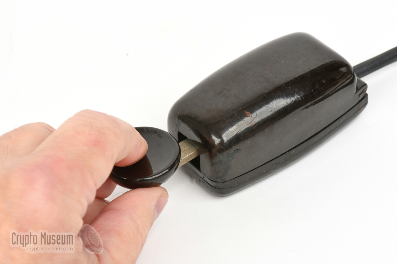
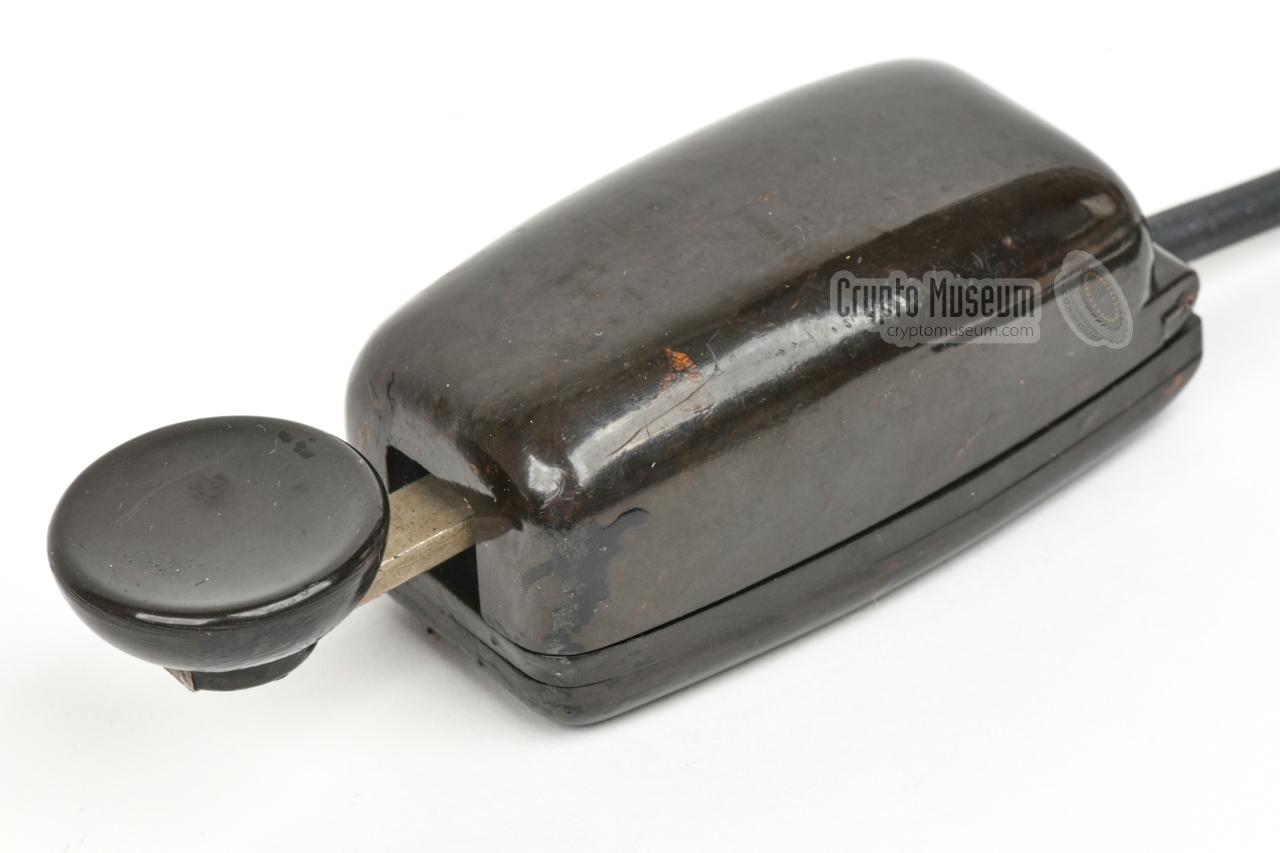
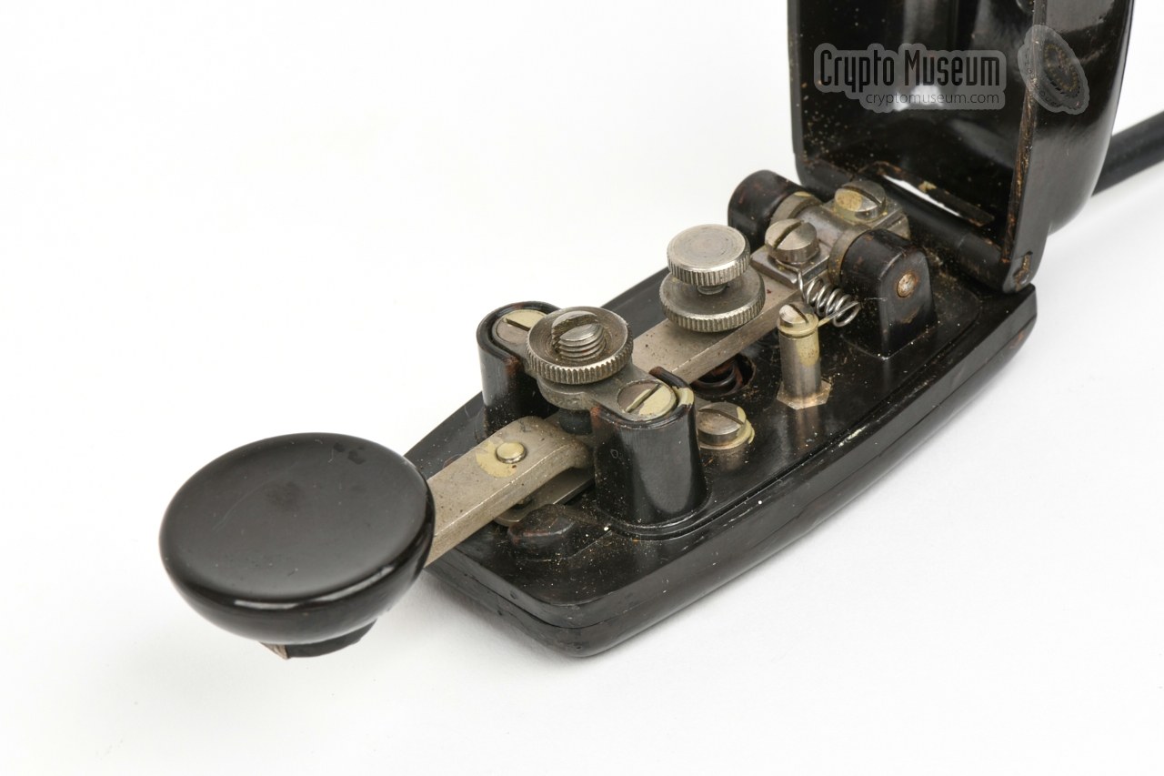
Although the RST-101 has a
built-in morse key (at the top right),
sending a message this way would be rather inconvenient.
For this reason, an external morse key was supplied as well.
Probably to cope with post-war shortages, the external morse keys
were sourced from WWII surplus from Germany – the former enemy.
The image on the right shows the miniature morse key,
nicknamed Mouse, that had also been used with some
German spy radio sets during the war.
➤ Other morse keys
|
|
|
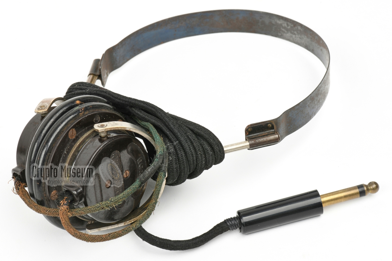
Like the morse keys, the headsets that were supplied with the
RST-101 also came from German WWII surplus. The image on the right
shows a typical German Kriegsmarine pair of headphones that was reused
with the RST-101.
The headset was connected to the transceiver by means of an (American)
6 mm PL-55 jack plug, which should be inserted at the
left edge of the front panel,
below a small hinged cover.
|
|
|
It seems likely that the non-para version of the RST-101 was used with
an external power supply unit (PSU) that was powered from the mains. As we
don't know for certain that this was indeed the case, and because we
haven't found a matching PSU, we've created the power cable shown in the
image on the right.
The cable is terminated with three banana plugs that can be connected to
two external PSUs: one for the LT and one for the HT voltage.
|
|
|
|
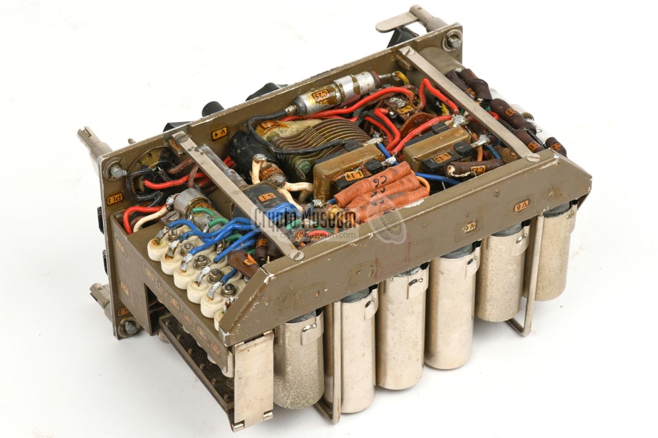
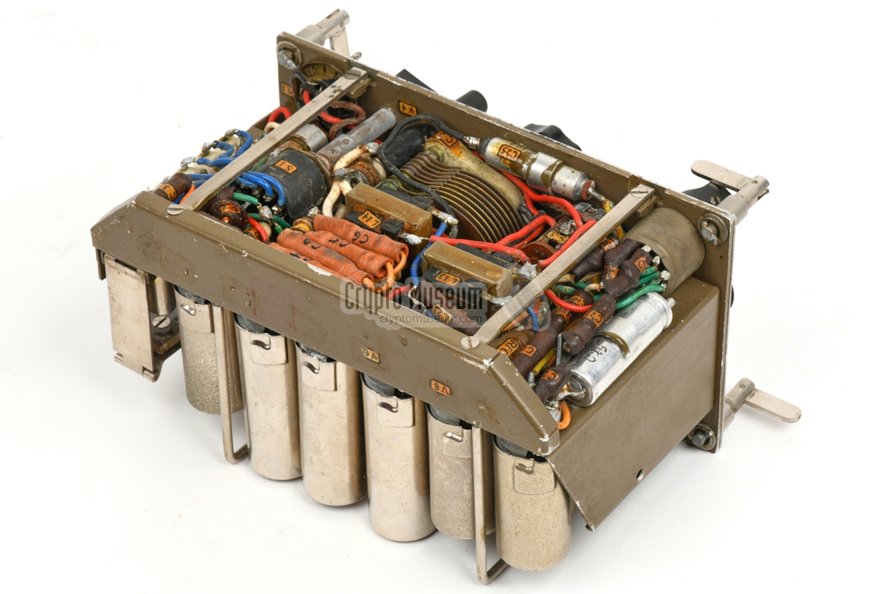
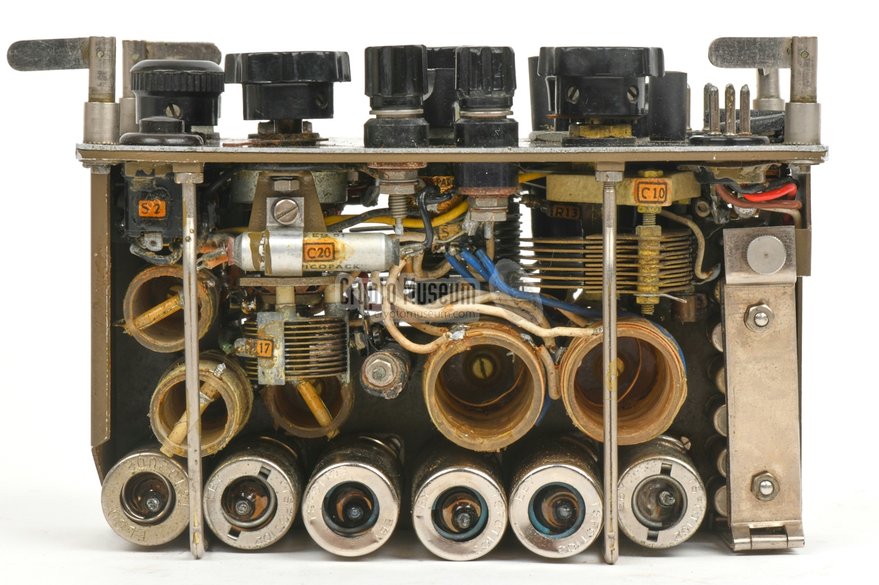
There is not much space at the bottom side, where the passive parts
and the wiring from the components at the top side, are densely
packed together. Reparing this unit was probably not a simple task.
That said, the serviceable parts — the valves and the crystals —
are easily accessible.
|
The transmitter consists of a Pierce oscillator for CW (A1),
built around a 6AG5 valve (V1)
with one of six selectable crystals (XTAL).
The oscillator is followed by an RF amplifier – also known as
the power amplifier (PA) – which consists of
two 6AQ5 valves 1
in parallel configuration (V2, V3).
The 3-12 MHz frequency range is divided over two bands
— 3-6 MHz and 6-12 MHz with some overlap —
selectable with a rotary switch (S3) at the front panel.
The frequency of the PA valve is adjusted with the (calibrated)
adjustable capacitor C8 in combination with one of the selected
anode coils (L2/L5). An inductively coupled light bulb (B1)
helps to find the optimum adjustment.
The tuned antenna circuit, of which the coil (L1/L4) is coupled
to the PA anode coil (L2/L5), can be adjusted with variable capacitor
C10. Another light bulb (B2) is present to find the optimum setting.
The lamp is shunted by a 47Ω resistor that can be disconnected
momentarily by pressing switch S4 on the front panel.
When sending messages in CW, the morse key is used to connect
and disconnect the cathode of all transmitter valves (V1, V2, V3)
simultanously
(not just the oscillator). The morse key is connected in parallel
with a push-button (S2) on the front panel.
|
|
-
The original manual erroneously specifies the two PA valves
as 6AG5 [A].
|
The self-regenerative receiver consists of a detector stage with feedback,
built around a 6AG5 valve (V7), followed by an AF amplifier,
also built around a 6AG5 (V8).
The 2-12 MHz frequency range is divided
into three bands (3-4.5 MHz, 4.5-1.5 MHz and 7.5-12 MHz with
some overlap) selectable with a rotary switch (S6) at the bottom right of the
front panel.
It selects between three coils that form a tuned circuit with a variable
capacitor (C17). The tuned circuit is inductively coupled to the antenna,
and – with some extra windings – to the kathode of the first valve (V7).
Feedback is controlled by a potentiometer (R16) which contols the g2
voltage. It allows the valve to oscillate in all three bands. The output
of the detector is fed via a capacitor (C23) to the AF amplifier valve (V8).
At the output of the AF amplifier is an inductor (L14), which is shunted by the
headphones that are connected to socket J2. The headphones must have an
impedance of 8000Ω.
It should be noted that at the time of introduction (1958)
the design of the receiver — basically a simple TRF circuit —
was already dated. It was known from wartime experience with the British
Mark VII (Paraset),
that a regenerative receiver without a pre-amplifier, produces a strong
RF signal that can be heared from miles away. An adversary can use it
to find the location of the secret station by means of
Radio Direction Finding (RDF),
even when the transmitter is not used.
|
The desired mode of operation is selected with the MODE-selector,
or function switch, located at the bottom right of the
front panel,
just above the serial number. It has four positions, the first of
which is OFF. The diagram below shows the wiring
of the MODE-selector in the OFF position.
The second position enables the
transmitter, which is powered by the hand generator
through (PL1).
The third position enables the receiver, which is powered by a battery
pack that is connected to the 3-pin receptacle (PL2).
In the forth position, the receiver is powered by the hand-generator.
The 350V generator voltage is lowered to 150V
by means of an 8k resistor (R14)
and is stabilised with the OA2 valve at the bottom right (V6).
In positions 3 and 4, the transmitter is disabled.
|
|
When we aqcuired the RST-101 featured on this page, it was in unknown
condition. It had been stored in a moist place for several years, and
it had not been used since it was decomissioned in the mid-1980s. Before
bringing it back to life, the most
obvious corrosion was removed,
and the individual parts were thoroughly cleaned where necessary.
Next, the circuit diagram was studied.
|
This was necessary, as we wanted to find out which voltages should be
applied to which pins of the power receptacles, but also because a
loose wire was found in the bottom section.
The wire turned out to belong to the ground-side of C25, and was
probably broken as a result of mechanical stress from opening and closing
the enclosure. It was easily fixed by using a tin-plated spring (correct for
the era) to solder the wire
to the remaining ground contact of C25.
The rest of the wiring and parts were visually inspected, but no
further defects were found.
|
|
|
|
It was decided that the 4-pin receptacle
for connection of the hand-operated power generator
(located at the bottom left of the front panel, was best suited
for powering the device and testing all circuits, as it allows the use
of both the transmitter and the receiver from a single source.
|
Only two voltages are needed in this case: 6V for the filaments (LT),
and +350V for the anode voltage of the transmitter (HT). In receive
mode (position 4 of the MODE-selector), the +350 is converted
to a stabilised +150V for the anodes.
As none of the original power cables had been found with the set,
a suitable replacement had to be made. This was particularly difficult,
as the connectors (audio plugs from the Philips EELA era) are rare,
and the 4-pin variant is even rarer. Luckily, a matching chassis-part
from Amphenol was found, and was converted to a cable-part.
|
|
|
|
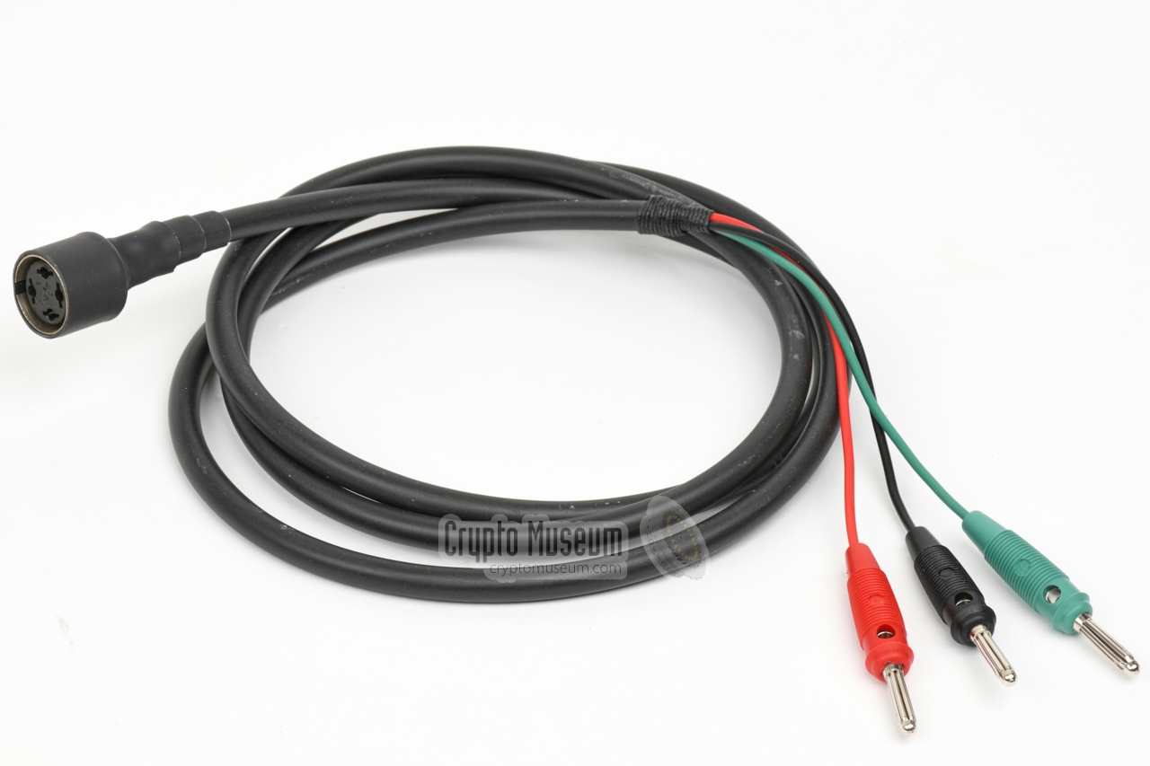
The resulting cable is shown in the image below. It has three wires —
black (0V), red (+6V) and green (+350V) — that allow the RST-101 to
be connected to suitable mains PSUs.
Before power was applied, the LT lines were checked for resistance,
and the HT lines were checked for shorts.
|
As the power LT and HT lines were fine, power was applied; first
the 6V (LT) and after approx. 10 seconds the HT voltage, which was gradually
raised from 50V to 350V, whilst checking the capacitors on the power
rails. As one capacitor was running hot (C26) it was swapped for a modern
alternative before resuming the test.
The transmitter worked straight away on any of the inserted crystals.
It was easily tuned for the highest power output and the tone it produced
was stable and clean. With the receiver we were less fortunate. It produced
no noise whatsoever.
|
|
|
|
First the AF-stage (V8) was tested by placing the volt-meter probe
at the anode-side of L13. It immediately produced
a 50 Hz hum in the headphones, which proved that
V8 was working fine. It was discovered that the detector (V7)
didn't work as the cathode was not connected to ground.
|
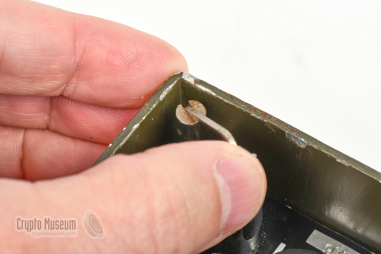
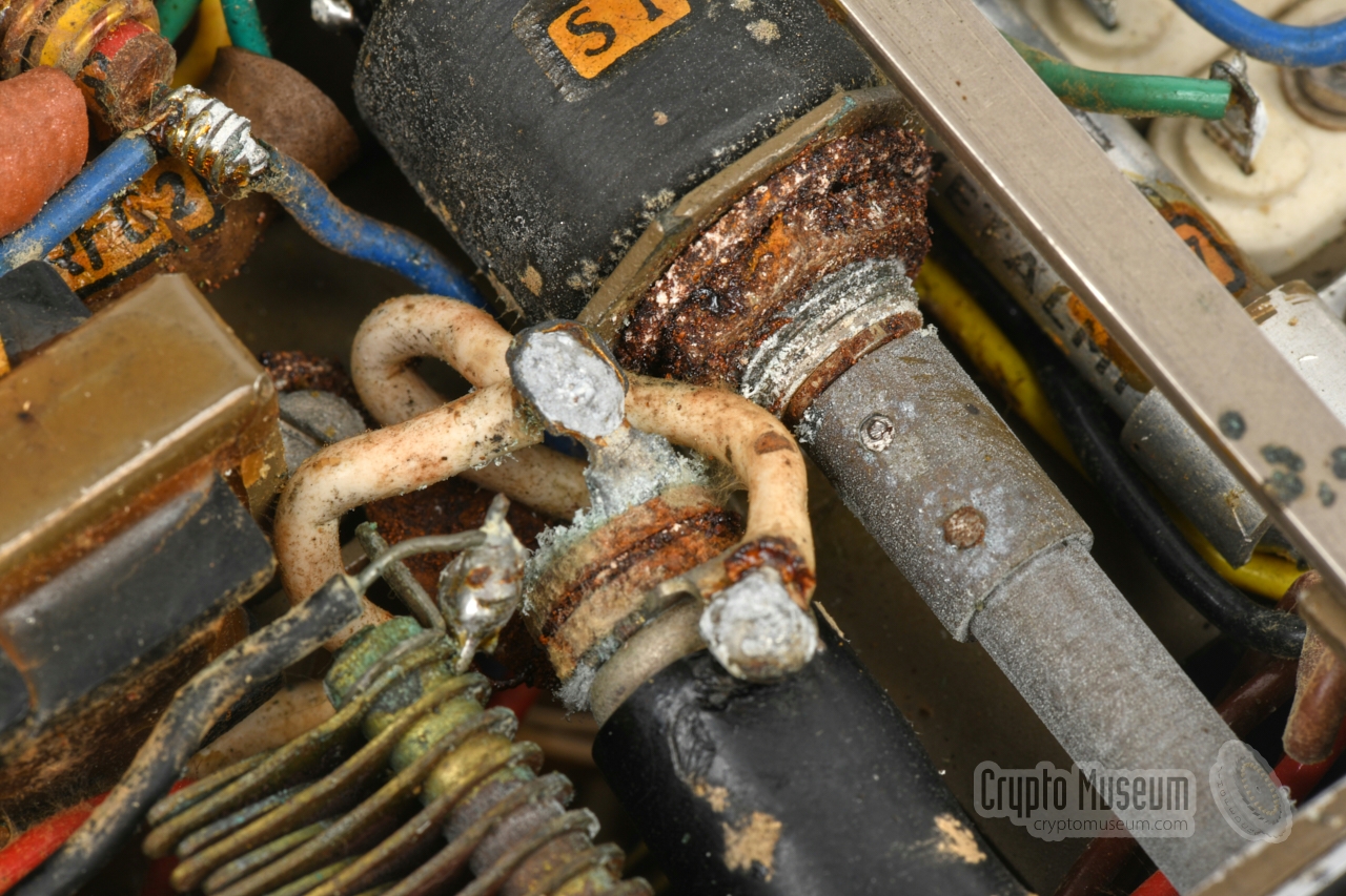
This was caused by a broken wire between the cathode of V7
and the common contact of the band switch (S6c).
The original (yellow) wire was too short and was broken at
the solder joint of band switch, as shown in the image on the right.
Reaching the wire was not easy however, as the common contacts of
the band switch (S6) are hidden from view by the outer (green) wiring
and by several components that are soldered directly to the
contacts. After partly disassembling the wiring of S6 and temporarily
removing some of the components, the contact could be accessed.
|
|
|
|
The broken wire was replaced by a similar (yellow) one, and the
cathode of V7 was checked for continuity to ground. Next, the
wiring of S6 was restored and the removed components were soldered
back in place. After powering the unit up again, the receiver
worked immediately, and was able to pick up the weak signal from
our test generator. Next it was tested on an antenna, and stations
could be heard on all bands. The sensitivity is as specified
in the manual: 7µV.
|
|
So far, the following restoration work has been carried out:
|
|
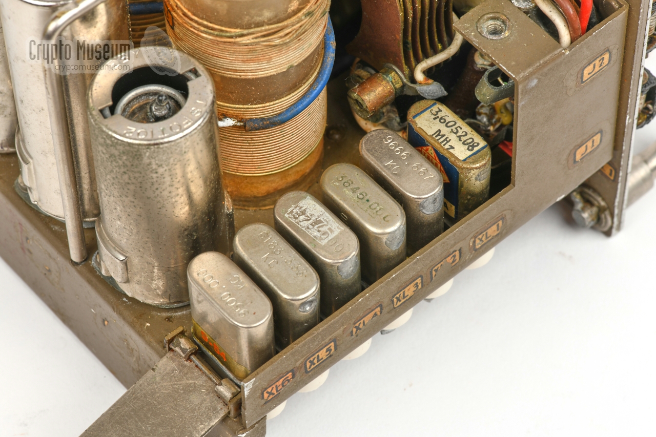
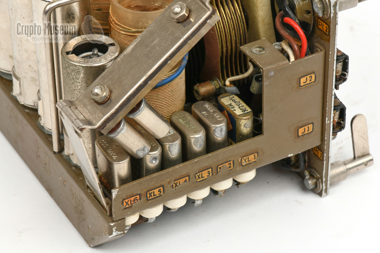
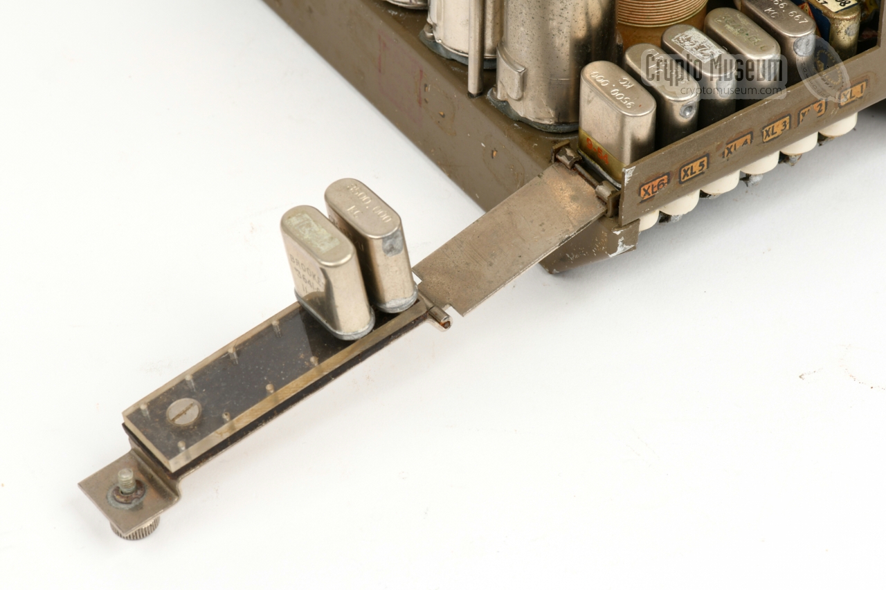
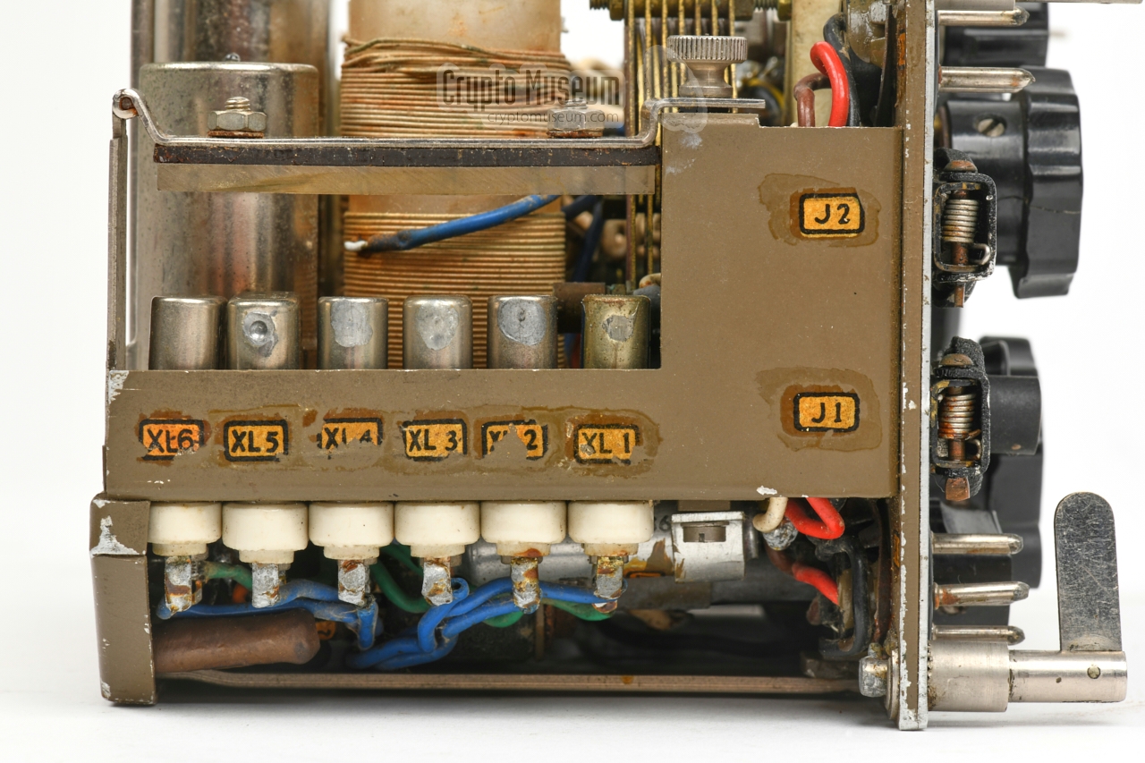
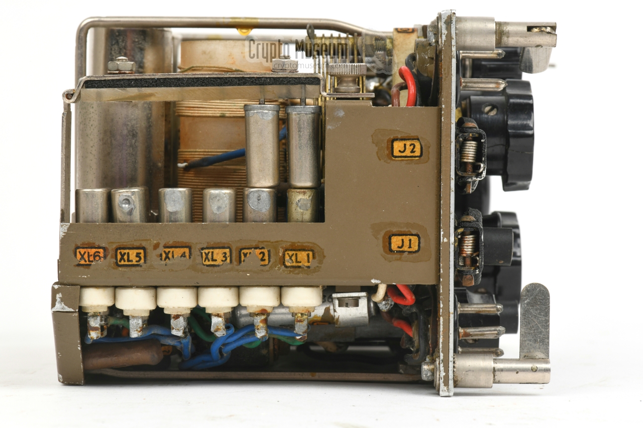
At the left hand side of the chassis are crystal sockets for the six
fixed channels. A hinged metal bracket is positioned over the crystals,
probably to prevent them from falling out. However there is about
12 mm of headroom
above the crystals, so the metal bracket has no appararent function.
|
|
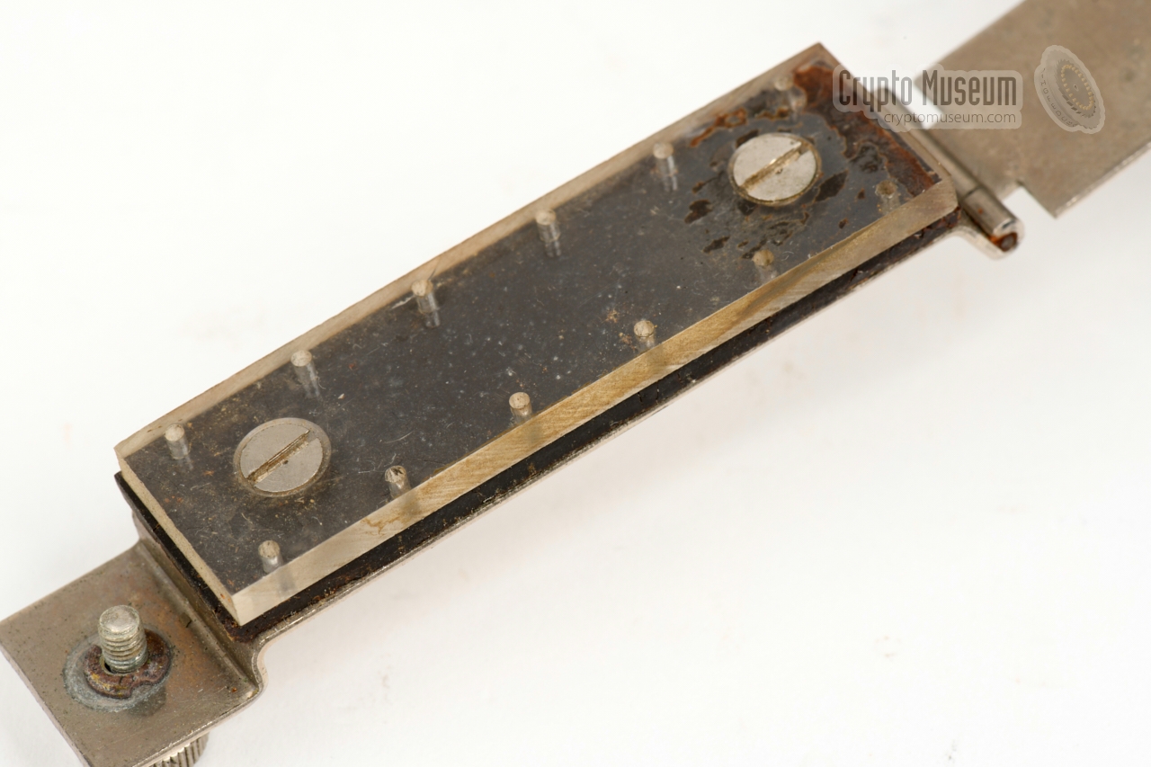
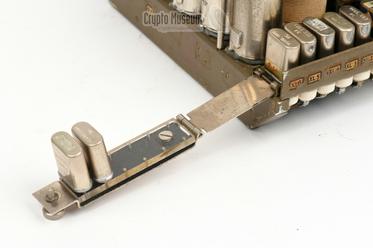
It is far more likely that the bracket has been mounted the wrong way around
at the factory back in 1958.
As the rubber layer below the plexiglass holder had partly desintegrated,
we decided to give it a try. We disassembled the bracket from the hinge,
and mounted it the other way around.
|
Somehow the altered assembly
makes more sense. The rubber pad and the
plexiglass holder nicely fit in the embossed area of the
bracket. And more importantly:
the extra crystals now fit.
As the above described manfacturing 'mistake' seems to be present in all
surviving RST-101 units, it seems likely that it affects all production
units, and that the additional crystals were never fitted, unless the
user modified the bracket as described above.
It is also possible that only a certain production run was affected.
It would be nice to hear
this from original users of the unit.
|
|
|
For the above modification we had to remove the old rubber pad, part of
which had hardened and part of which had become sticky. After treating it
with thinner, the rubber became rock solid – like glass – and could
easily be removed with a knife. It was then
replaced by a neoprene pad.
The image above shows what the imaginary crystal must have looked
like, when 12 crystals had to be fitted in the RST-101 with the wrongly
assembled crystal holder bracket. It could just be 14 mm high.
At the left is the shape of a normal
HC6/U crystal,
of which the body is 20 mm high.
To the best of our knowledge, HC-6 crystals with a height of 14 mm
never existed, making it more plausible that the bracket has indeed been
mounted the wrong way around at the factory.
➤ More about crystal shapes
|
|
In 2024/25, German radio amateur Thomas Hppe (DJ5RE) acquired
an RST-101 with serial number 65, which happened to be disfunctional.
It appeared to be necessary to replace several parts and carry out a
few modifications in order to make the device more reliable.
Below is a description of the work he carried out when restoring
this device, along with updated circuit diagrams.
|
The transmitter did not produce a clean CW signal, which
led to a chirping sound when pressing the morse key. This appeared
to be caused by the circuit around the antenna current lamp (B2).
In rest (when S4 is closed), B2 is bridged by resistor R13.
Although this resistor is specified in the circuit diagram as
47Ω, it is constructed of three parallel connected resistors
with the combined value of 82Ω. A solution was found by
connecting the adjustable capacitor (C10) directly to switch S3c,
which effectively bridges resistor R13. The result is shown in
the green area below.
|
| |
Modified transmitter circuit diagram. Modifications in the green area.
|
|
In the receiver circuit, capacitors C20, C25, C26 and C27 were tested.
As they were all in bad shape, it was decided to replace them. Note
that if the mode selector will be modified as described below,
the +ve side of C26 must be connected to a different point (to the top of V6).
It was also found, that the capacity of the antenna input capacitors
(C11, C12, C13) is too high, which potentially overloads the Audion circuit.
Furthermore, with a relatively low antenna (which is the case with the
supplied antenna wire) it allows the capacity between antenna and ground
to have an effect on the tuned circuit and, hence, the adjusted frequency.
This is particularly noticable when the antenna wire moves in the wind.
The problem can be solved by lowering the capacity of C11 to C13,
as shown in the modified circuit below (modifications in the green area).
|
| |
Modified receiver circuit diagram. Modifications in the green area.
|
|
When Thomas first tested the device, switch S5d appeared to be broken.
The contacts of this switch, which is part of the
5-deck mode selector,
were completely burned and were beyond repair.
Apparently Thomas is not the only one to experience this problem,
as Antony Wedgwood (G0TJD) reported the same problem in
The VMARS newsletter of December 2001 [3].
|
| |
Modified circuit to circumvent burnt switch contacts. Modifications shown in green.
|
The problem with the contacts of S5d is caused by the fact that C26
in the receiver is recharged each time the receiver (RX) is enabled.
The inrush current is large enough to damage the relatively small
contact of the selector. The complex arrangement of S5b, S5c, S5d and S5e
is only needed to allow two different power plugs: the 4-pin PL1 and
the 3-pin PL2. The latter was intended for separately powering the
receiver, which in practice is hardly ever used.
Thomas fixed the problem by disconnecting PL2 and bypassing switches
S5b, S5c and S5d, as shown in the modified circuit diagram above.
He also moved capacitor C26 from the central contact of S5e to the
OA2 stabilizer (V6). All modifications are shown in the above diagram in green.
|
|
The receiver can be powered by a combined battery pack
which delivers +6V for the filaments and +150V for the anodes of
the valves. To power the receiver from the battery pack,
connect the battery pack to the 3-pin receptacle at the top left
of the front panel and set the
MODE-selector to position (3). Note that the transmitter can
not be operated from the battery pack.
The diagram below shows the pinout of the male receptacle on the
front panel of the RST-101.
|
- Ground
- +6V LT
- +150 HT (RX)
|
|
|
At the bottom left of the front panel is a 4-pin receptacle for
connection of the hand-operated power generator. When operated,
the generator delivers +6V for the filaments of the valves and +350V
for the anodes of the transmitter valves. To operate the transmitter,
the MODE-selector should be set to position (2).
To operate the receiver from the generator, select (4).
The diagram below shows the pinout of the male receptacle on the
front panel of the RST-101.
|
- Ground
- +6V LT
- Ground
- +350 HT
|
|
6AG5 is a miniature sharp-cutoff pentode, designed for
use in RF and IF amplifiers, up to 400 MHz. It is housed
in a 7-pin miniature button glass enclosure (E7-1).
In the RST-101 it is used in both receiver stages (V7, V8),
and in the oscillator of the transmitter (V1).
The diagram below shows the pinout, as seen from the
base of the valve (i.e. the solder-side of the socket).
➤ 6AG5 datasheet
|
5AQ5 is a miniature beam-power pentode, designed for use in
the AF power output stage of a domestic television or radio
receiver.
It is housed in a 7-pin miniature button glass enclosure (E7-1).
The performance of the 6AQ5 is equivalent to the well-known 6V6-GT.
In the RST-101 two 6AQ5 valves are used in parallel configuration in the
transmitter's PA-stage.
The diagram below shows the pinout, as seen from the
base of the valve (i.e. the solder-side of the socket).
➤ 6AQ5 datasheet
|
OA2 is a miniature glow-discharge cold-cathode voltage regulator
valve (tube), housed in a glass T-5-1/2 enclosure, with a 7-pin
miniature button base (E7-1).
It has an anode voltage of 150V with a regulating range of 6V.
In the RST-101 it is used in combination with an 8k resistor to
convert the +350V raw voltage from the hand-generator,
to a stabilised +150V for the receiver.
➤ OA2 datasheet
|
Device Spy radio transceiver Purpose Agent communication Model RST-101 (Paraset) Manufacturer MBLE (Philips) Country Belgium Year 1958 Users SF Reconnaissance, stay-behind (SDRA-8, STC/Mob) Dimensions ? Weight ? Quantity 200 ~
|
Circuits RF Detector, AF amplifier Type Regenerative Frequency 3 - 12 MHz Bands 3 (see below) Modulation AM (A3), CW (A1) Input 600 Ω Sensitivity 7 µV S/N 6 dB Output 8 kΩ Antenna ¾λ Valves 2 x 6AG5, OA2 1 Power +6V (LT), +150V DC (HT)
|
3 to 4.5 MHz (70-100m) 4.5 to 7.5 MHz (40-70m) 7.5 to 12 MHz (12-40m)
|
-
The OA2 stabiliser in only used when operating from the hand-generator.
|
Circuits Oscillator, Power Amplifier (PA) Type Crystal operated Frequency 3 - 12 MHz Bands 2 → 3 to 6 and 6 to 12 MHz Output ≥ 5 W into 300 Ω Modulation CW (A1) Stability ± 104 (-20°C em +40°C) Antenna ¾λ Valves 6AG5 (oscilator), 2 x 6AQ5 (PA) Power +6V (LT), +350V DC (HT)
|
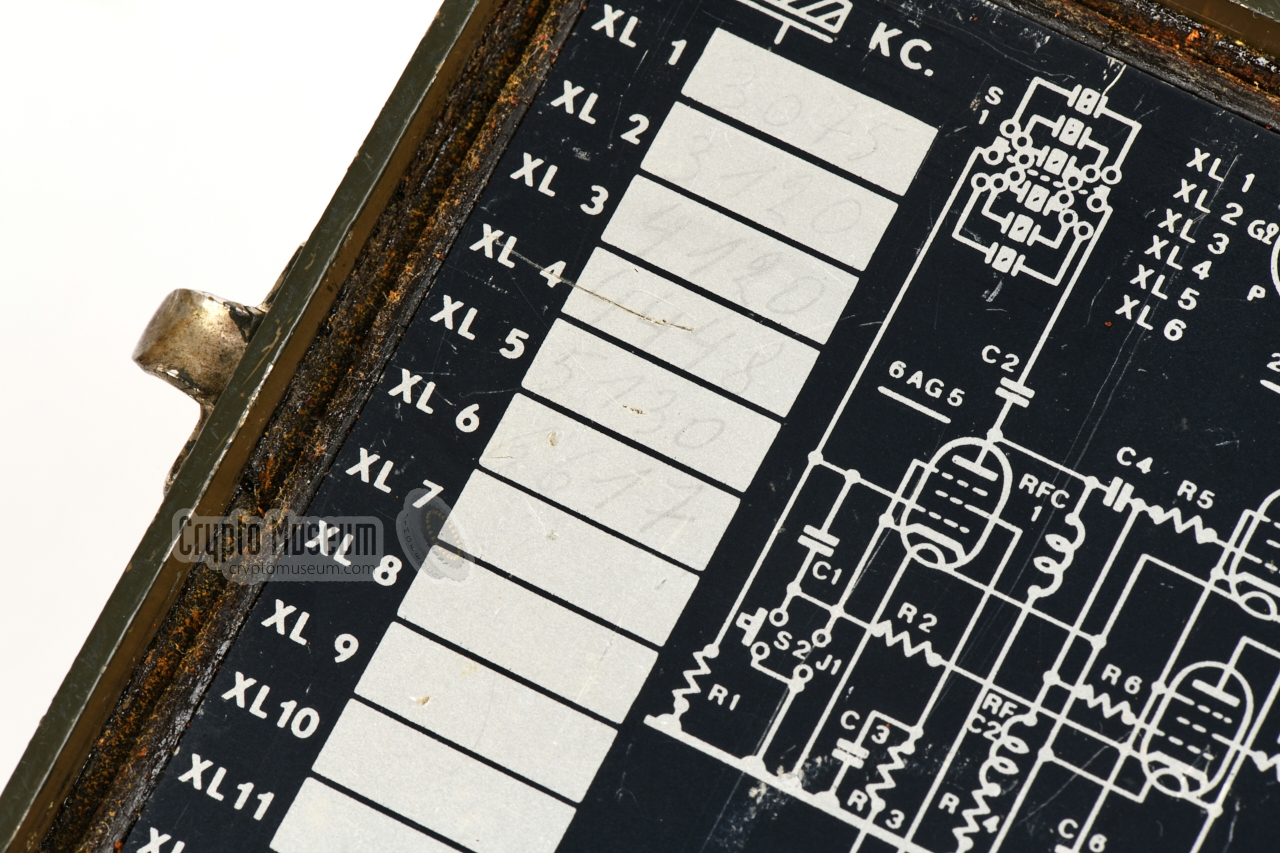
- 3075 kHz
- 3120 kHz
- 4120 kHz
- 4448 kHz
- 5130 kHz
- 6617 kHz
|
| • | ZA 00294 Bg | Transceiver (RST-101) |
| • | ZA 00295 Bg | Manual power generator |
| • | ZA 00312 Bg | Accessory box with tools and spares |
| • | TM 11102 Bg/NL | Operating instructions (Dutch) |
|
|
The transceiver is known under the following designators:
|
|
It is currently unknown how many RST-101 sets were manufactured and how many
have survived. By listing the serial numbers of the surviving sets, we may
get an idea of the actual production quantity. The serial number is imprinted
on a metal tag on the case lid, and at the bottom right of the
front panel of the device.
Note that the serial numbers are prefixed by 'BG' (Belgium).
|
65 Thomas Höppe, Germany 97 Private collector, USA 103 Private collector PA5E, Netherlands 116 Crypto Museum, Netherlands 120 Ben Nock, Military Wireless Museum, UK 129 Featured in Wireless for the Warrior [2] 139 eBay, December 2022
|
-
Document kindly provided by Louis Meulstee [2].
|
|
|
|
Any links shown in red are currently unavailable.
If you like the information on this website, why not make a donation?
© Crypto Museum. Created: Friday 04 September 2020. Last changed: Wednesday, 05 November 2025 - 12:11 CET.
|
|

|
|
|
|


![Canvas backpack. Item kindly donated by Thomas Höppe (DJ4RE) [6].](img/304307/001/full.jpg)
![Canvas bag. Item kindly donated by Thomas Höppe (DJ4RE) [6].](img/304307/000/full.jpg)

![Original morse key. Item kindly donated by Thomas Höppe (DJ5RE) [6].](img/303125/057/full.jpg)
![Original headphones. Item kindly donated by Thomas Höppe (DJ5RE) [6].](img/303125/063/full.jpg)
![Antenna wires on wooded spools. Item kindly donated by Thomas Höppe (DJ5RE) [6].](img/303125/054/full.jpg)
![Side bag with antenna mast. Item kindly donated by Thomas Höppe (DJ4RE) [6].](img/304308/001/full.jpg)
![Antenna accessories and tripod. Item kindly donated by Thomas Höppe (DJ4RE) [6].](img/304309/000/full.jpg)
![Power generator. Item kindly donated by Thomas Höppe (DJ4RE) [6].](img/304310/017/full.jpg)
![Power cable. Item kindly donated by Thomas Höppe (DJ4RE) [6].](img/304310/009/full.jpg)
![Image kindly provided by Louis Meulstee [2]](img/rst101_acc.jpg)


