|
|
|
|
|

|
|
OWVL DDR Stasi 32621 → ← 32028
Speech/morse generator
Gerät 32620 (Device 32620) is a digital speech generator, developed around
1982/83 by the Institut für Kosmosforschung 1 (Space Research Institute)
in the former DDR (East-Germany)
and manufactured at the ZWG in Berlin.
It was the successor to an analogue tape-based device known as
Schnatterinchen,
and was used by the East-German
Ministerium für Staatssicherheit
(MfS), also known as the Stasi,
for sending secret coded messages to its agents anywhere in the world,
via the mysterious numbers stations that used to be operated
on the short wave (SW) radio bands.
The device is known by different names, including
Eiserne Frau (iron lady) and Stimme (Voice).
|
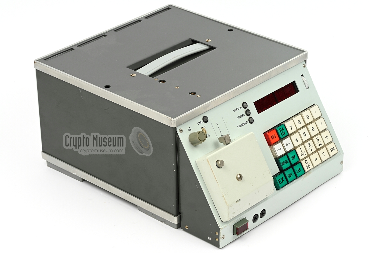
Device 32620 measures 290 x 260 x 135 mm and weighs approx. 7.1 kg. It has
a sloped front panel with a 25-button keypad, an 8-position
alphanumeric LED display and a 5-level paper tape reader.
Messages can be entered manually on the keypad, via the serial port
(by modem), or by means of a pre-recorded paper tape (telex).
Once a message is stored in the internal memory it can be played out
either in morse code or as a spoken
message, using a digitized female voice.
When the device is switched off, the messages are retained by
an internal NiCd backup battery.
|
|
|
Device 32620 was developed in the early 1980s, to replace the ageing analogue
tape-based Schnatterinchen (cacklerina) devices.
The first protypes were tested by the Stasi in 1983, and in 1984 it was taken
into production.
It was used by Stasi (MfS)
department HV A (Hauptverwaltung Aufklärung), for passing messages
— generally encrypted with the unbreakable
One-Time Pad —
to its agents operating in Western countries.
It was also used by the intelligence services of other
Warsaw Pact
countries, including the Soviet Union (USSR)
and Poland, and countries like Cuba.
For speech digitizing and duplication of the speech module,
Device 32621 — Programmierhilfe für Gerat 32620
(Programming aid for Device 32620) —
was available separately.
It is currently unknown how many 32620 device were made, but it is likely
that the initial production batch in 1984 comprised ~ 50 devices,
and that at least two batches of ~ 50 units each were made later.
The device featured here, is a model 32620.2 with serial number 8704.
It was manufactured in February 1987.
In 1989, 6 more units were ordered for
the HV A (8/A) and 27 for the IZSU, of which 15 were to be delivered in January 1990 and the remaining 12 in December 1990 [3]. 2
➤ Hear what the voice sounded like
➤ Operating instructions
|
 |
-
Part of the Akademie der Wissenschaften der DDR
(East-German Science Academy).
-
In November 1989 the Berlin Wall fell,
so it is unclear whether these 27 units were delivered.
|
The images below provide a quick overview of the features of the 32620.
All controls are at the front of the device. At the bottom left is the
mains power switch. Above it is a sloped panel with a 25-button keypad
for user input. Above the keypad is an 8-position LED matrix display
on which the current state of the device is shown. To the left of the
keypad is a 5-level paper tape reader.
At the top left is the volume control knob for the internal speaker
that is used for monitoring the output of the device. To its right is
a switch to enable the line output (located at the rear). A LED
shows whether or not the line output is currently enabled.
To the left of the display are 3 further LEDs that show the
mode (SPEECH or MORSE) and whether the STANDARD
configuration is used.
All connections are at the rear of the device. There is a fixed
power lead for connection to the 110, 127 or 220V mains AC network.
In addition, the device can be powered by an external 12V DC source,
such as the battery of a car. The audio
line output is available on a KS-51 socket.
It must be enabled with the LINE switch at the front
panel and can optionally be terminated at 600Ω with a switch
aside the socket. There is a built-in speaker, but it is also
possible to connected an external speaker. Depending on the orientation
of the plug, the internal speaker can be disabled.
At the bottom edge is a 6-pin military socket that carries the
serial communication lines. They are connected to the SIO
(USART) on the CPU board and allow synchronous or asynchronous
serial communication. It is currently unknown whether this feature
was supported by the firmware. 1
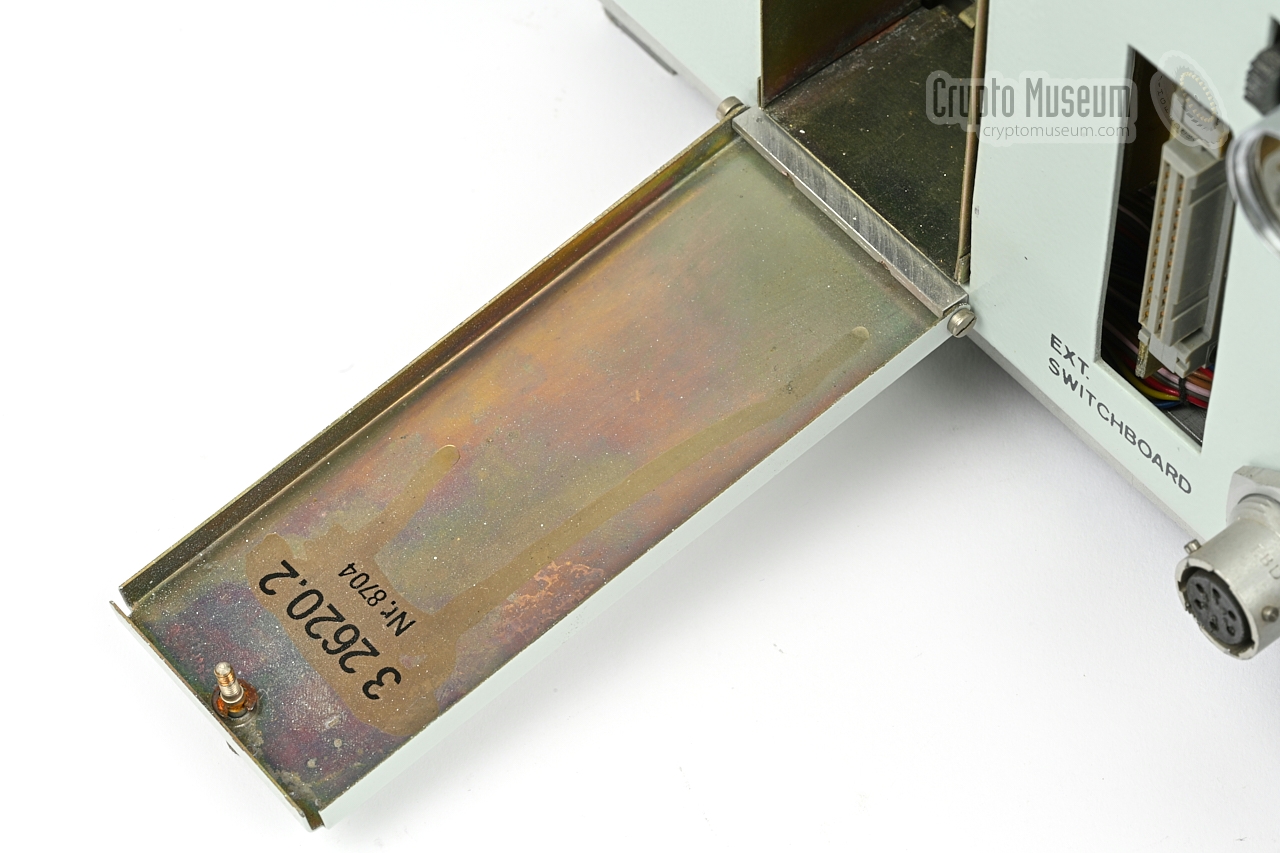
At the centre is a grey 26-pin EFS-26 socket on which several
I/O lines are available. It allows the device to control external
equipment – e.g. a transmitter – and to be remote controlled itself by
external events. At the left is the hinged lid
behind which the speech module must be installed.
➤ Operating instructions
|
|
-
In the manual [A] this feature is listed as in Vorbereitung
(in preparation).
|
- 32620
Original version, developed in 1982/83 and released
in 1984.
The firmware is spread over two EPROMs:
one on the CPU board and one on the I/O Epansion board.
It supports the use of one speech board that holds
6 EPROMs of 8KB each (48KB total). It is suitable only for languages
that can be fitted into these 6 EPROMs, such as German. It is not
suitable for Spanish, as that requires at least 8 EPROMs.
- 32620.2
This is the improved version which was developed and released in 1987.
It supports the simultaneous use of two speech boards, which is
necessary for languages which cannot be fitted into 6 EPROMs, such as
Spanish.
For this reason, changes were made to both the memory map
and the designation of the PIO lines. This version can address up to
96KB of speech data (instead of 48KB). The device featured here,
is of this type.
|
In addition to the above versions, there are production variants
of the various plug-in cards. For example: the speech card, which
contains six 2764 EPROMs was later replaced by a card that contains
three 27128 EPROMs. The two cards are functionally identical however.
|
The diagram below shows how the 32620 was used. In most cases it
was placed close to the actual (high-power) short wave transmitter (TX),
or at least in the same building, such that the
600Ω line output of the 32620
could be connected directly to the input of the transmitter.
The line output carries the audio signal (speech or
morse).
In case morse code
was used (rather than speech), a switched contact
from the relay board was commonly connected to the transmitter.
Although a coded message could be entered on the device's keypad,
it was usually delivered by courier (or telex)
on 5-level punched paper tape,
and loaded into the device via the
tape reader at the front panel. Alternatively, the message could
be sent directly from the Spy Centre via a (secure) telephone or data line,
using a modem that was connected to the device's serial port.
|
|
The sound samples are recorded with
Linear Pulse Code Modulation (LPCM)
using a sample rate of 8 kHz and a bit-depth of 8 bits.
Below are the contents of the German and Spanish speech modules.
The third one — All English words by Polish speaker — was reconstructed
at Crypto Museum from real life recordings.
Click any of them to discover what the voices sounded like.
|
|
The audio file below is a real broadcast from a Russian station (in German)
that was recorded in April 2014 by Karsten Hansky in Germany [8].
Click here for more real broadcasts.
|
HELP PLEASE —
At present, German and Spanish are the only languages of which
we have the original EPROM contents. These are the only two
languages that were recorded with the same female voice at
Funkobject Kasselberg in the DDR. All other languages
(e.g. Polish, English and Russian) were recorded by the country
which operated the device, using the
32621 programming aid.
We would very much like to add other languages to our list.
If you can provide the EPROM contents for such languages,
please contact us.
|
From 1961 onwards, the woman 1 shown in the image below,
was one of the female speakers of the East-German numbers stations.
Like most of the speakers, she was living with her family on the compound
of Funkobject 2 Kesselberg.
Initially the numeric messages were read live in one of the small studios
in the basement of the Kesselberg site, where they were recorded
on tape.
|
The tapes were then played back at specific times via a strong
short wave (SW) transmitter with an output power between 10 and 100 kW.
In 1963/1964, whilst she was was on leave to give birth to a child,
she was asked to lend her voice to the new
Schnatterinchen device,
that had just been developed. In the small studio in the basement,
each word had to be fitted onto a piece of audio tape that was just
12-15 cm long.
According to her own account [4],
the words Achtung (Attention) and Sieben (Seven) were the most
difficult to record. Furthermore, the words had to be pronounced in such
a way that they could be discriminated unambiguously through a noisy
narrowband short wave radio channel.
The pre-recorded tape segments were later mounted onto
the discs of the Schnatterinchen device.
Some time later she was also asked to lend here voice to the Spanish
version of the machine, which was subsequently recorded in the studio
of the DDR broadcasting service 3 in Berlin.
In the early 1980s, the same voice was digitized for use in
the digital Device 32620 featured here.
|
|
|
For the lady in the picture, this meant the end of an era, but
in the following years, she frequently tuned in to the Stasi frequencies
on the short wave radio band, to confirm that here voice was still being
used. In January 2010, she wrote a letter in which she explained here
role as the voice [4].
➤ Read the full letter
|
-
The name of the female speaker is currently unknown.
-
Literally translated 'Radio Object' - here used to identify a site.
-
Rundfunkhaus der DDR, Nalepastraße, Berlin (East Germany).
|
Device 32620 was developed around 1982, as a replacment for the
earlier tape-based Device 32028 (Schnatterinchen).
The first protypes were tested by the Stasi in 1983. It is likely
that the first production run was in 1984, followed by another one
in 1985.
In 1987, the device was upgraded to support languages that required
more storage space, such as Spanish, resulting in model 32620.2.
The device featured here is of this type, and was made in February 1987.
In 1989, six more units were ordered for the HV A (8/A) and 27 for the
IZSU — the international cooperation with the
Soviet Union.
Of these 27 units, 15 were scheduled for delivery in January 1990,
whilst the remaining 12 would be supplied in December 1990.
It is unclear whether these devices were actually delivered, as on
9 November 1989 the Berlin Wall fell,
leading to the reunification of East and West Germany on 3 October
1990. This period is known as The Wende.
It is possible that all 27 units, or at least
the last 12 units, were never supplied to the Soviet Union.
The picture above was taken in a Stasi warehouse
around the time of the Wende (~1990). It shows around 25 devices
divided over several piles. It is likely that these devices were
decommissioned in 1989 and were stored here awaiting their demolition.
On two of the devices the serial numbers are visible: 8703 and 8704,
which indicates that they were produced in February 1987. Note that the
latter (8704) is the one that is currently
held in our collection.
|
|
Below is an overview of the sound samples for the German language,
along with their associated keys and
morse code equivalents.
Note the distinct – non-standard – pronunciation.
➤ Play all
|
| Key | Morse | German | Pronunciation | Description | # |
|
|
| 0 | - | Nul | Nul | Zero | 1 |
| 1 | .---- | Eins | Eins | One | 2 |
| 2 | ..--- | Zwei | Zwo | Two | 3 |
| 3 | ...-- | Drei | Drei | Three | 4 |
| 4 | ....- | Vier | Vier | Four | 5 |
| 5 | ..... | Funf | Fun-nuf | Five | 6 |
| 6 | -.... | Sechs | Sechs | Six | 7 |
| 7 | --... | Sieben | Sie-ben | Seven | 8 |
| 8 | ---.. | Acht | Acht | Eight | 9 |
| 9 | ----. | Neun | Neu-en | Nine | 10 |
| : | ...- | Achtung | Achtung | Attention (start) | 11 |
| / | -..-. | Trennung | Trennunk | Separation (space) | 12 |
| + | .-.-. | Ende | Ende | End (stop, end of transmission) | 13 |
|
|
|
Predecessor
Schnatterinchen
|
|
|
Device 32620 was the successor to an analogue machine known as
Schnatterinchen (Cacklerina),
that was developed in 1964/1965. It used short pieces of audio
tape – fitted onto circular discs – as the storage medium.
➤ More information
|
|
|
|
Quite a bit of footage that shows the 32620 in action, can be found
on YouTube, most of which was published by Peter Staal in The Netherlands [6]
and were recorded at the home of German collector Detlev Vreisleben in 2010
[2]. They show one or more machines in action and demonstrate how to alter
the language. Below are some examples.
|
Various demonstrations of a 32620 device on YouTube
|
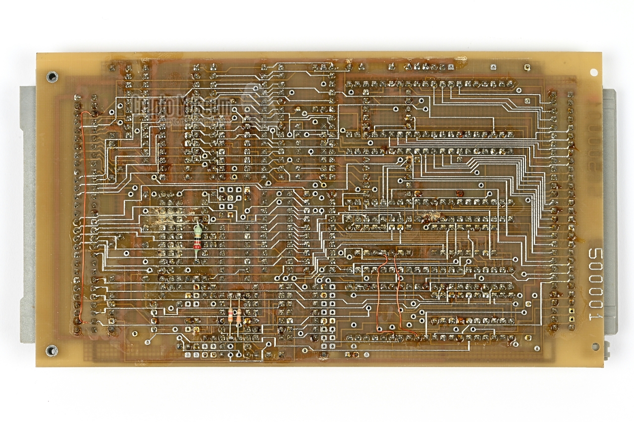
Below is the block diagram of the 32620. The device consists of a rack with
plug-in cards, a power supply unit (PSU) and several PCBs that are fitted
behind the front panel. The PSU is not shown in the diagram.
At the heart of the system is the CPU board (DBZ-80-1), which is built
around a Zilog Z-80 microprocessor, 1 two parallel I/O expanders (PIO) and
one serial port (SIO).
The PIOs are used for interfacing to the keypad and the display. The SIO,
also known as a USART,
is for (a)synchronous serial communication with the outside world. It allows data
to be sent to the device via a telephone modem.
Also present on the CPU board, is the EPROM 2 that contains the
firmware, and two SRAMs of 4KB each.
The CPU runs at 2.458 MHz (crystal frequency 9.832 MHz).
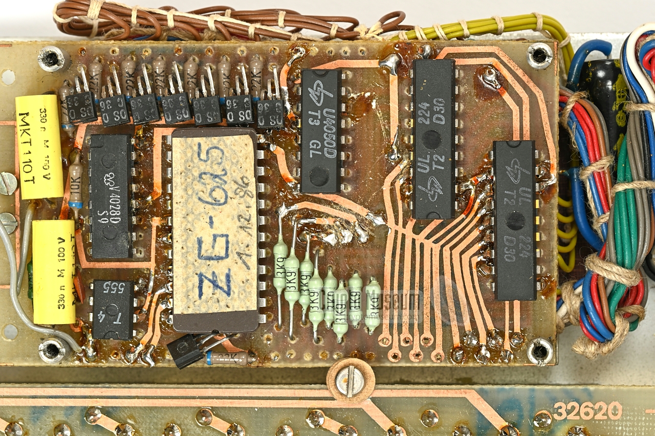
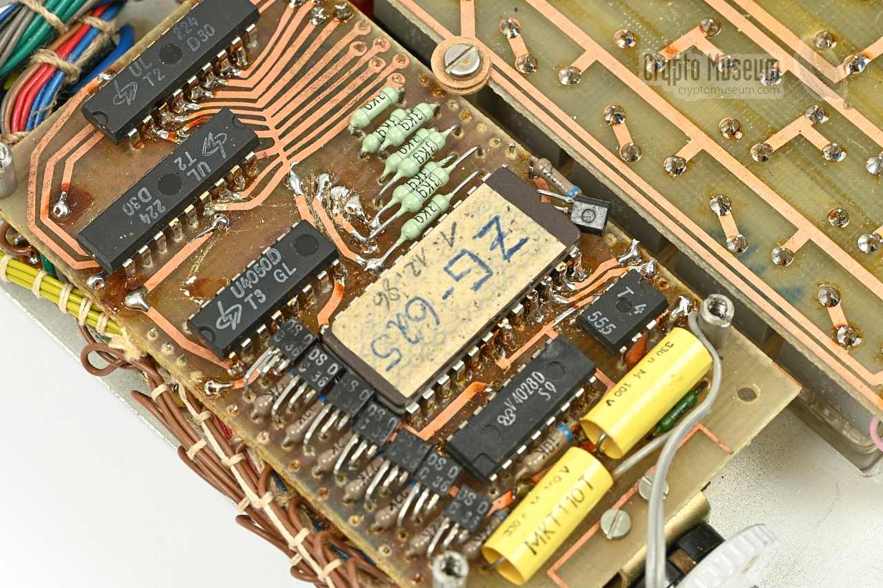
An additional board (DBE) provides two additional PIOs that are used
for interfacing the relay board, the audio board
and the tape reader (at the front panel). On version 1 of the
device, this board also contains a second 2716 or 2732 EPROM. On version
2 of the device (32620.2), this EPROM is omitted, whilst a double-size 2764
EPROM (8kB) is fitted on the CPU board.
The audio board contains the digital-to-analog (D/A) converter
and the audio amplifier. It provides a signal to the built-in speaker, plus a
line-level output for the radio transmitter. Although the developers initially
experimented with the C5658D – an D/A converter produced in the DDR –
they eventually settled for the Soviet produced K174 PA 1A 8-bit D/A converter [10].
The relay board provides a number
of galvanically separated (isolated) contacts that can be used to control
external equipment. It also has a number of inputs that allow the device to
be triggered by external events. The relay board also contains a NiCd
backup battery for the CMOS SRAM.
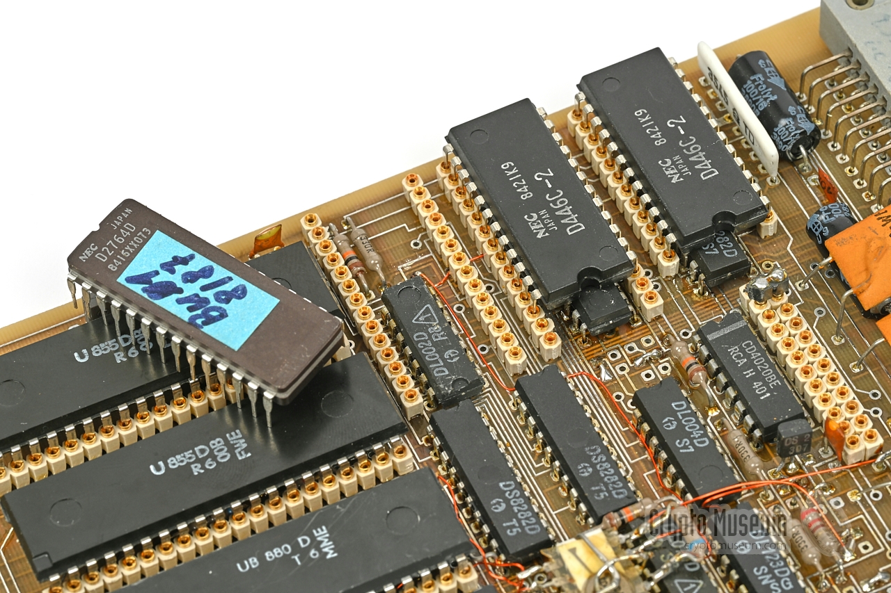
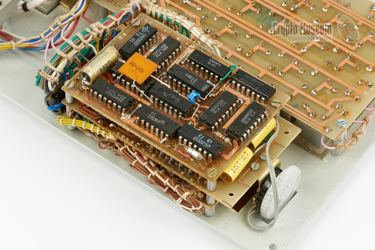
The speech data (i.e. the sound samples) is held in the separate
speech module, which should be intalled behind the
hinged lid at the rear of the device.
The speech module consists of one or two PCBs
(speech cards),
each of which holds six 2764 (8KB) EPROMs and additional logic circuits.
|
|
-
Or the Eastern Bloc variant UB880. ➤ Wikipedia
-
Type 2716 (2KB) or 2732 (4KB). Version 2 of the CPU board has
a 2764 (8KB) EPROM.
|
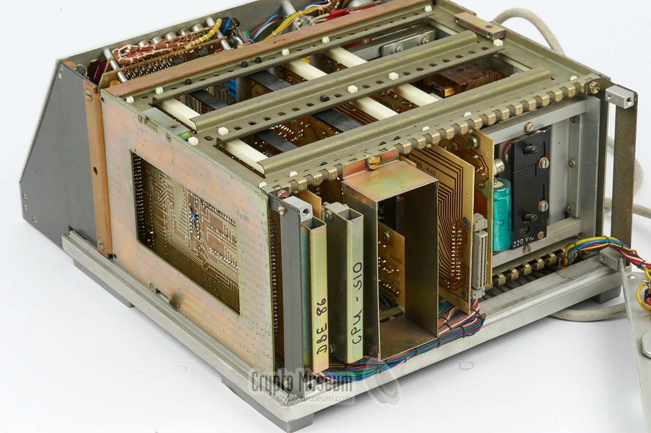
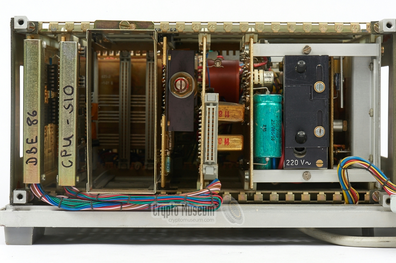
|
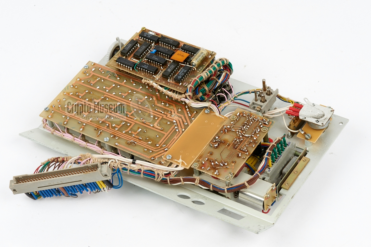
The device consists of two building blocks: the system unit, which consists
of a backplane with a number of plug-in cards and the mains power supply unit
(PSU), and a sloped front panel, behind which the remaining printed
circuit boards (PCBs) are hidden. The interior can be accessed by removing
four screws from the rear panel and two screws from the top, after which the
top, rear and side panels can be removed. The front panel is held in place by four screws
at the corners.
|
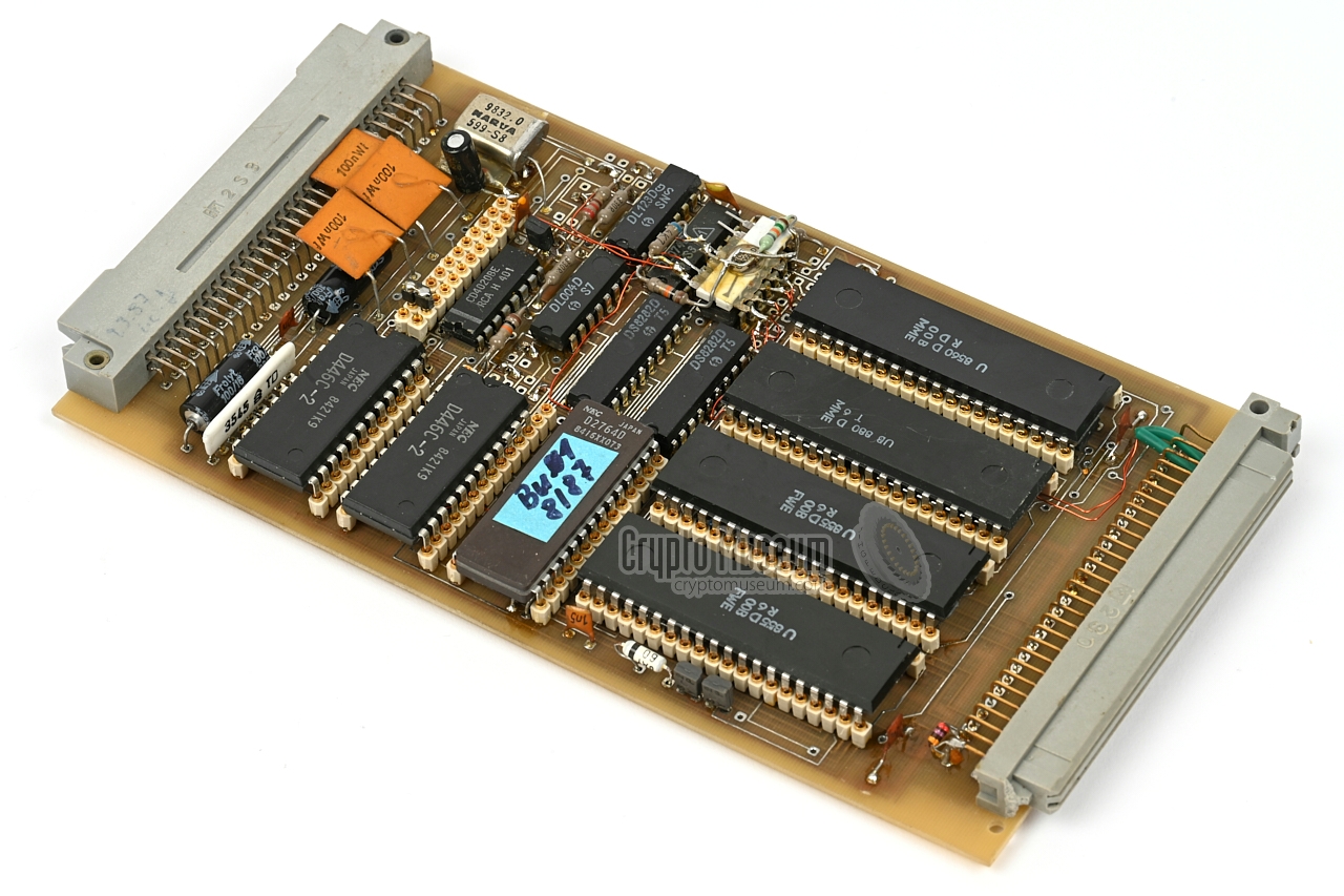
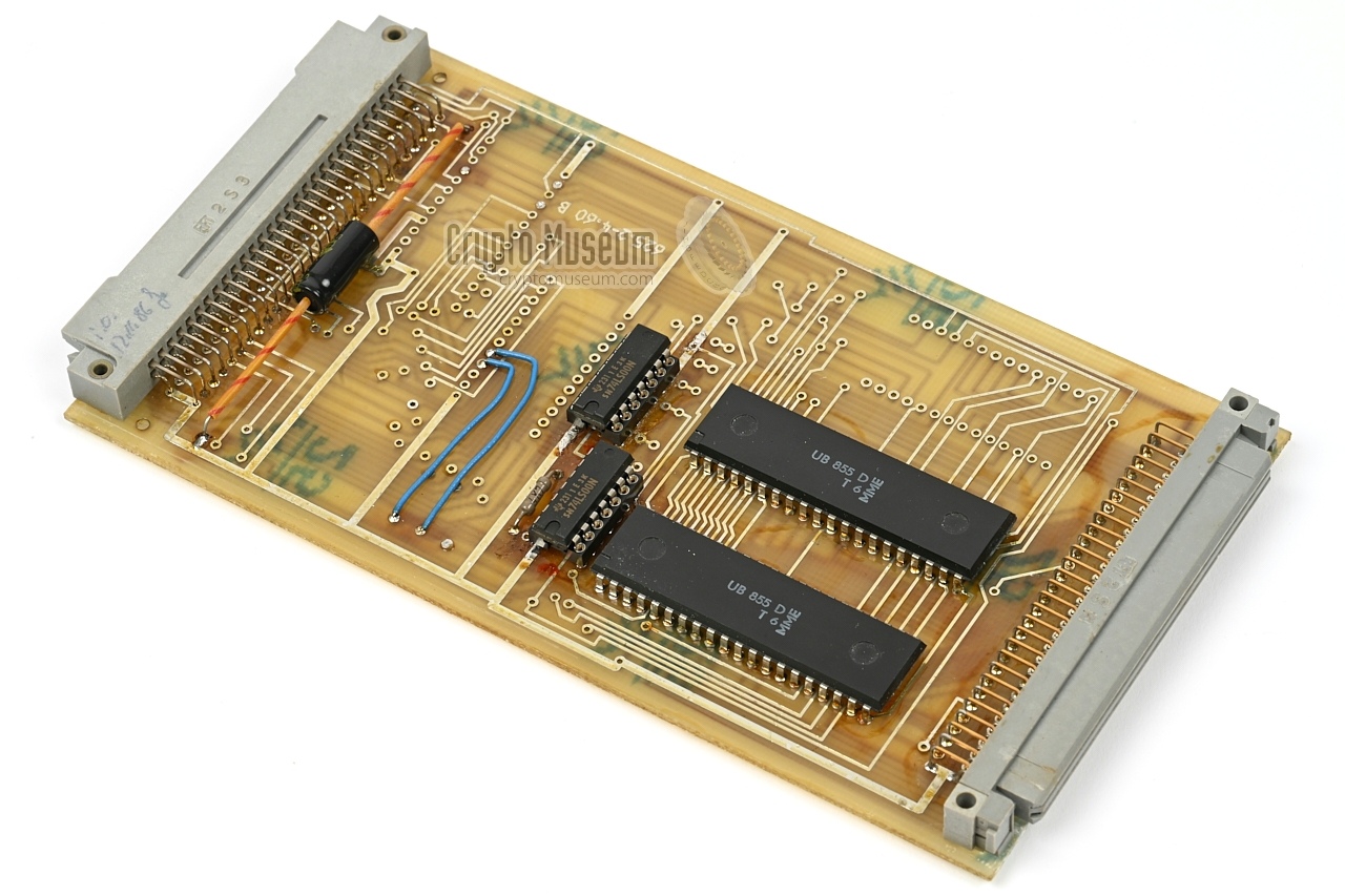
The CPU board is the heart of the device. It is built around a UB880
microprocessor made by MME – an unlicenced microprocessor based on the
design of the Zilog Z-80 and made in the DDR [9].
It runs at 2.458 MHz and is complemented by a SIO and two PIOs.
The latter are the interface to the keyboard and the display, both of which are
located at the front panel.
This board also contains the two SRAMs (i.e. the message buffer) and the
EPROM with the system firmware. Note that on version 2 of the board (shown
in the image on the right), the EPROM is twice as large as on version 1,
whilst the EPROM of the adjacent expansion board is omitted.
|
|
|
As the 58-pin EFS58 AB backplane connector does not have enough
pins to bring out all the I/O lines from the two PIOs, an extra
EFS58 AB socket is provided at the rear end of the board.
This socket is fitted with an EFS58 plug that is wired to the front
panel, as shown in the image on the right. The wire bundle is long
enough to allow an extension board
to be fitted between the CPU card
and the backplane (for repair).
The expansion card (to the left of the CPU card), it fitted
with a similar plug and wire bundle.
|
|
|
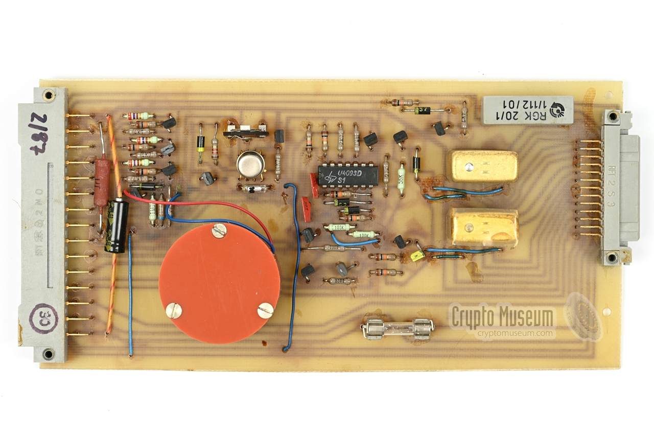
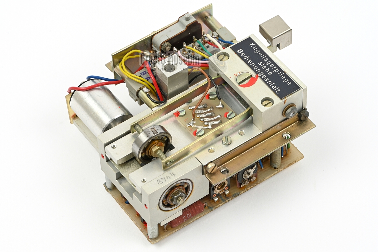
The interfacing capabilities of the Z-80 platform are further enhanced
with the expansion board shown in the image on the right. It holds two
additional PIOs that are used to drive the audio board,
the relay board and the tape reader.
It also holds the select lines for the speech cards.
On version 1 of the device (32620), this board also holds a second EPROM.
This EPROM is missing from the expansion board in version 2 devices
(32620.2).
At the rear end of the card is an additional EFS58 AB socket on which
the I/O lines from the PIOs are brought out.
|
|
|
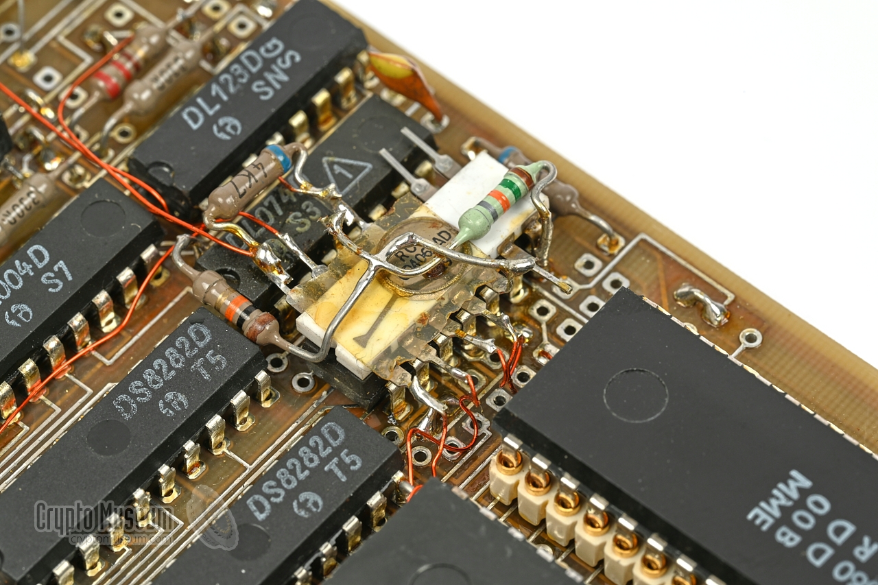
The audio board holds the digital-to-analog (D/A) converter and the audio
amplifier. It drives the built-in loudspeaker (embedded in the rear panel) and
also provides the (600Ω) line output for connection to a
short-wave (SW) transmitter.
At the centre of the edge of the board is the 600Ω output transformer.
The output level can be adjusted with the recessed potentiometer.
|
|
|
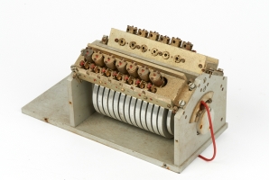
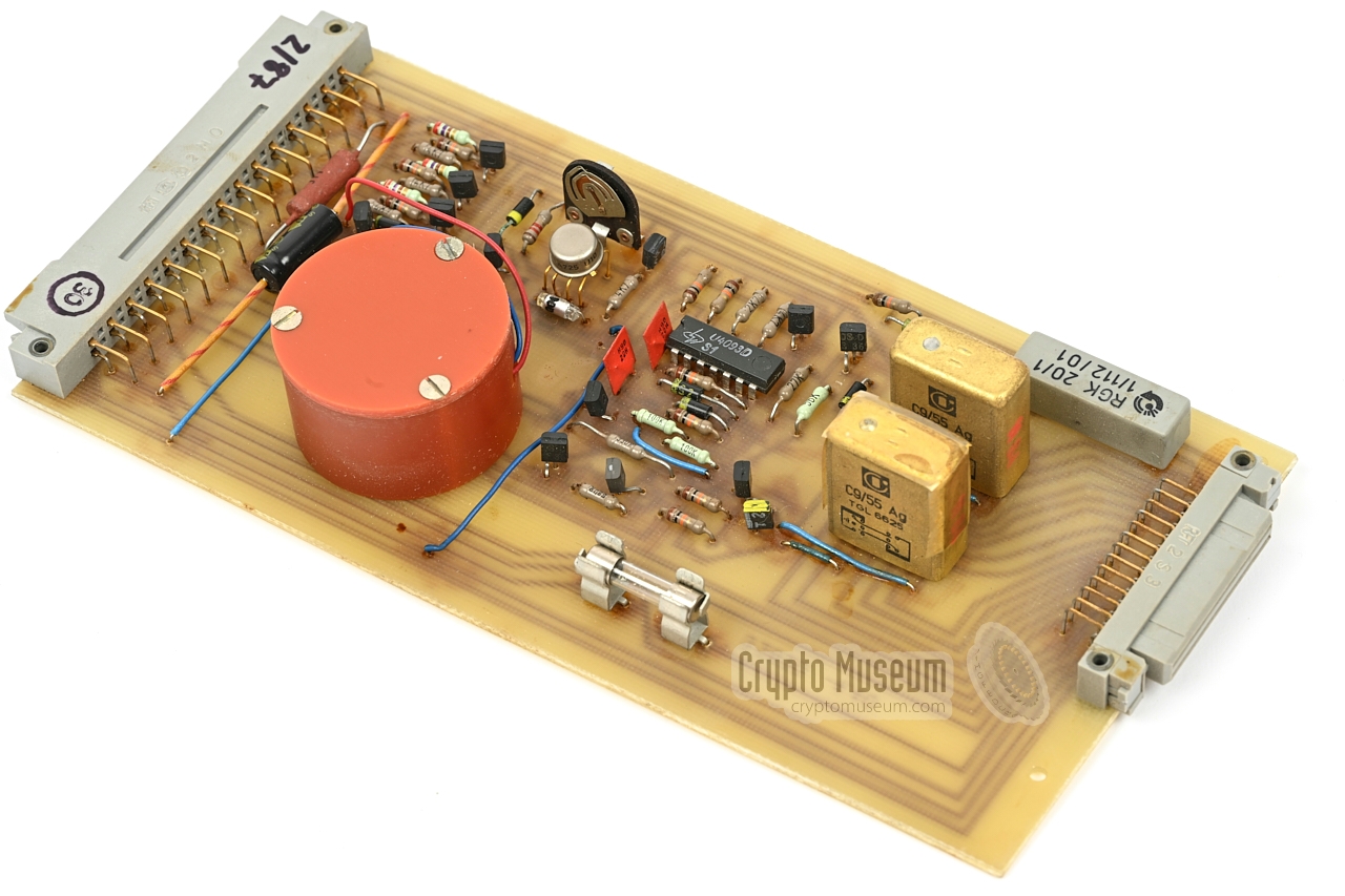
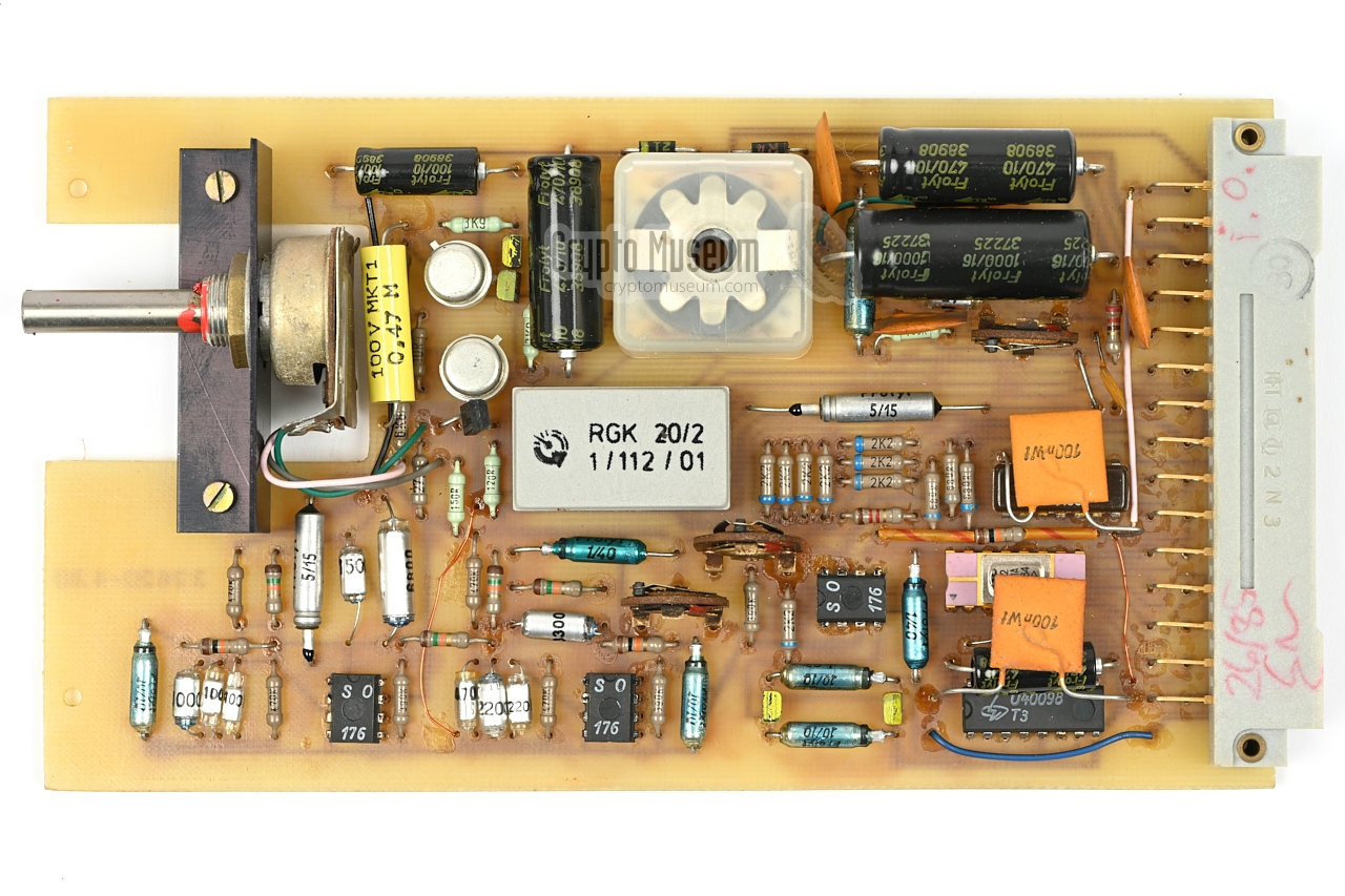
The relay board provides a galvanically separated interface to the
outside world. It has a number of isolated relay contacts that can be used
to drive external equipment. In addition, the board can receive external
triggers for starting a message.
This board als holds a rechargeable 2.4V NiCd battery (two stacked 1.2V
cells) that is used to retain the contents of the CMOS SRAMs (i.e. the
message buffer) when the device is switched off.
The battery is housed inside the orange cylinder.
|
|
|
The sound samples for a particular language are held in a
removable speech module
that must be installed behind the hinged lid
at the rear of the device.
The speech module contains one or two PCBs, each of which holds six 2764
EPROMs of 8KB each, in which the spoken words are stored.
As this module was missing from the device in our collection,
we have reverse-engineered it and have created the working reproduction
speech module shown in the image on the right.
➤ Reproduction speech module
|
|
|
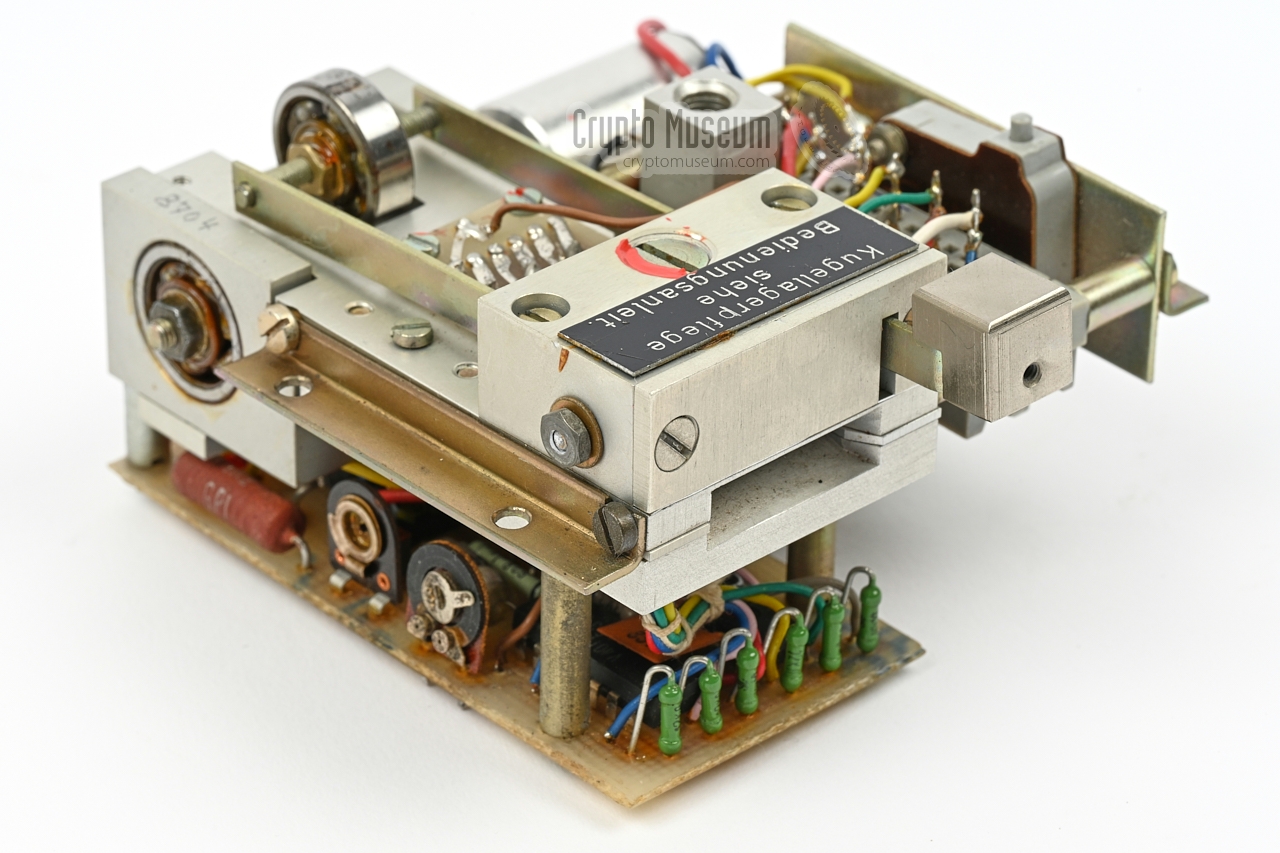
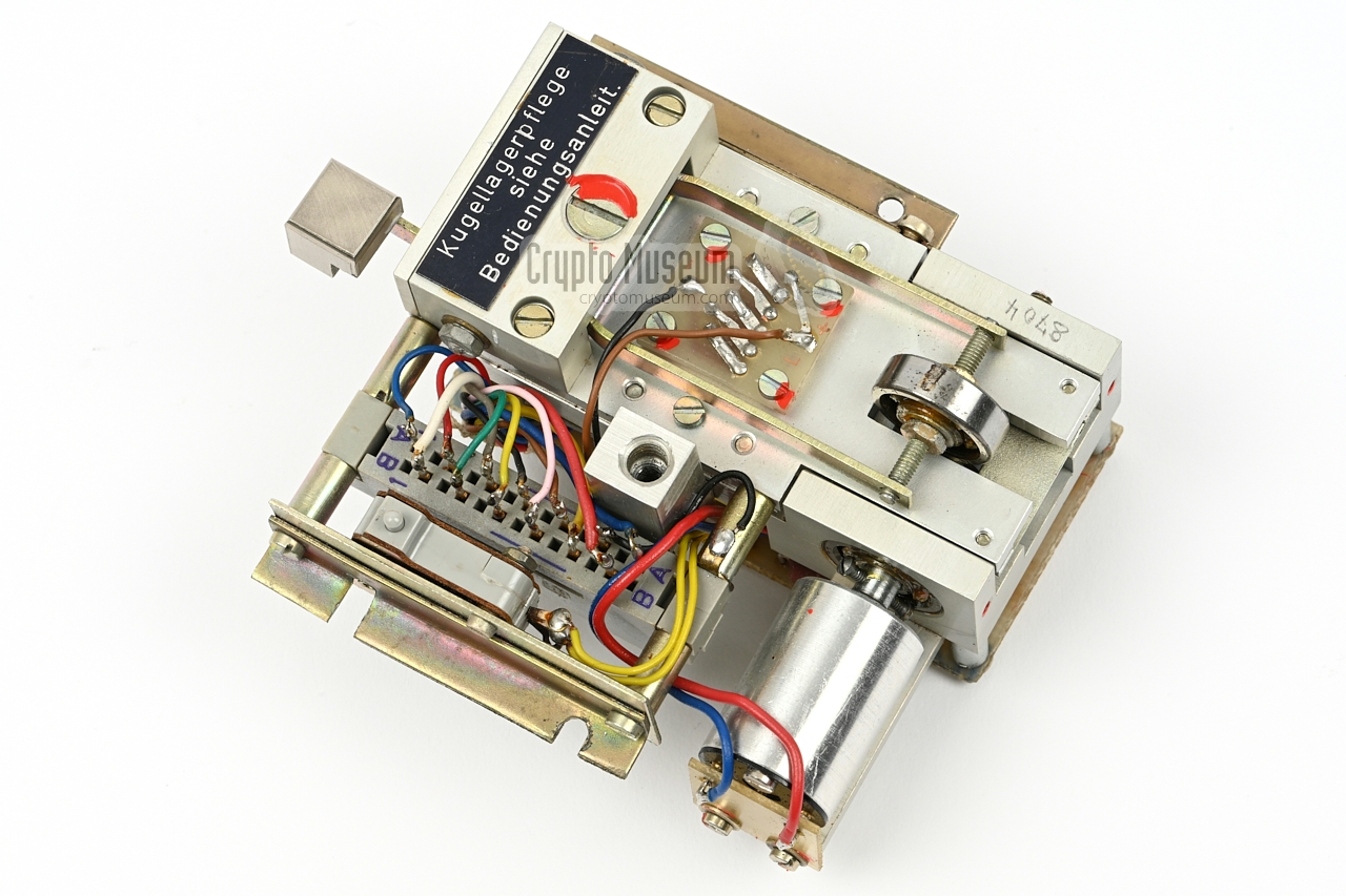
The remaining peripherals — the keyboard, the display, the tape reader and
a couple of LED indicators — are fitted behind the sloped front panel.
The front panel is electrically connected to the system unit by means of a wide
EFS-58 male connector and a small 3-pin connector.
The image on the right shows the rear side of the front panel. The large PCB
is the keypad. At the top left is a stack of three PCBs that are fitted
to the rear of the display. They hold the
character generator and the display driver. At the right is the tape reader.
|
|
|
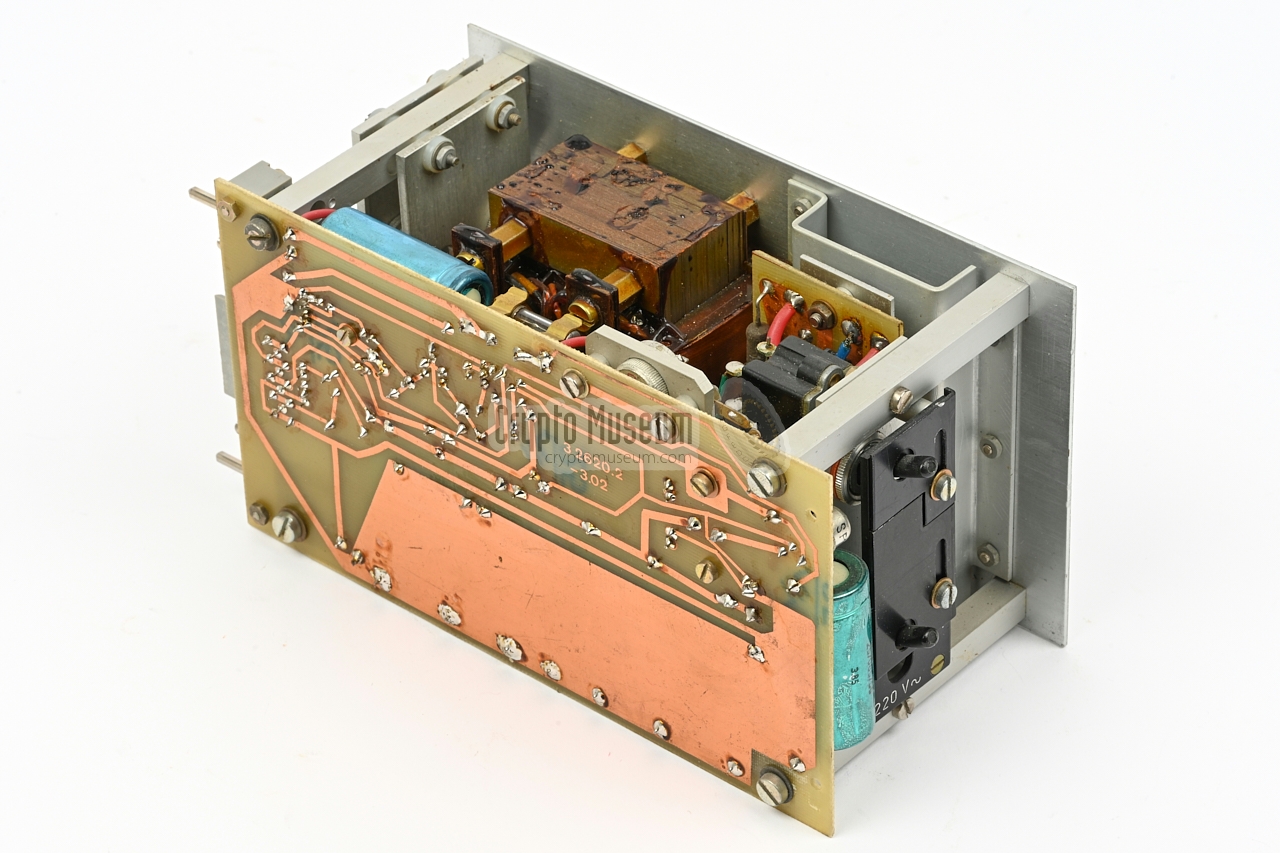
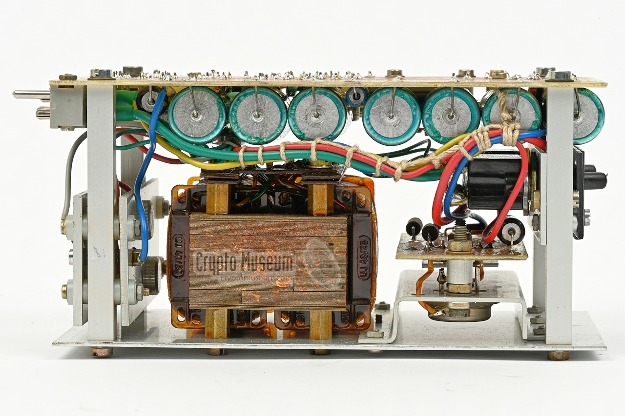
The rightmost plug-in board (seen from the rear) is the
Power Supply Unit (PSU).
It is also the largest plug-in unit and is connected to the backplace by means
of a combi-connector.
The mains power transformer is part of the PSU module.
The image on the right shows the PSU with the printed circuit board (PCB)
temporarily dismounted. It holds quite a few electrolytic capacitors
which should be replaced by modern alternatives as part of a restoration.
|
|
|
All removable parts (shown above) are interconnected via the backplane
shown in the image on the right. There are 7 vertically placed receptacles
for the plug-in cards, plus one horizontally placed receptacle the the bottom
right. The latter holds the wiring for the sloped front panel.
Note that in the original 32620, the receptacle for the secondary sound board
(3rd from the right) is unwired. This passive slot is mounted
upside down. In the later 32620.2 it is wired to the rest of the
backplane, but as it is mounted upside down, its connections are mirrored.
|
|
|
|
When we obtained our 32620 device in 2017 [1], it was in an unknown state.
The device had previously been working, but the speech module had gone missing
and could not be retrieved. After switching the device ON, the display showed
ERROR 15, indicating that the speech module
was indeed missing.
Pressing the STA/STP button, produced random characters on the display.
|
|
In addition, the second row of pixels of the LED display was dead,
as shown in the image on the right. It was decided to address this problem
first, as it did not require the presence of a speech module. The most likely
candidate for the cause of the problem, was the display driver.
|
|
|
|
After studying the circuit diagram [C], it was confirmed that the
cause had to be found either on the
character generator board
(1.12) in the circuit around D3 and VT2, or on the display board
(1.11) in the circuit around VT2. It turned out that the 22K
resistor R10 (between D3 and VT2) on the character
generator board had a crack. After replacing it, the display was
complete again.
|
The next problem to address was the random nature of the display contents
after pressing the STA/STP button. All plug-in cards were removed and
inspected physically. It turned out that the backup battery for the
SRAMs had been leaking and had caused damage to the relay board.
The NiCd cells were removed from the orange cylinder on the
relay board and were replaced by a 1.5F/5V
supercap. 1 The tracks at the bottom of the PCB were
cleaned and restored, and the
cylinder was refitted. In addition, the
wiring between the battery and the PCB was replaced.
|
|
|
|
It was now possible to clear the contents of the SRAMs, by
pressing (CLR) followed by (EX). It was also possible to set
the mode to MORSE, turn on the KEYBOARD MONITOR and enter a message
manually on the keypad. After entering random digits,
the message was terminated with the (+) key, after which the
display showed READY.
Pressing (STA/STP) now played back the message.
|
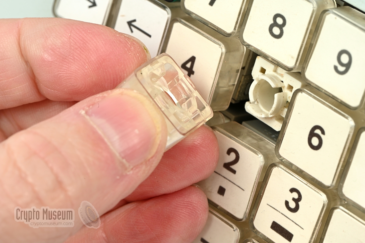
As some of the buttons on the keypad were unresponsive, several of
them were desoldered from the keypad PCB and taken apart, so that
their interior could be cleaned thoroughly.
Inside each button is gold-plated contact strip on which a spring-loaded
pad of conducting rubber is pushed down. Both the contact strip and
the rubber pad were cleaned with alcohol and tested for conductivity
before reassembling it and soldering it back in place on the keypad
PCB. This part of the restoration has improved the overall
reliability of the keypad considerably.
|
|
|
|
Another problem with equipment of this age is that most of the
electrolytic capacitors will have lost their capacity by now.
The Frolyt capacitors that are used in our 32620 are notorious for this,
as are the capacitors from many other brands from the
1970s-1990s, also in the Western world.
|
As a precaution, it was decided to replace all electrolytic capacitors
on all of the plug-in cards. When doing this, be especially careful
with the CPU board. It is very sensitive to electrostatic discharge
and the solder pads are very close to the adjacent tracks. As there is
no solder mask, a barely visible short circuit is easily created.
We also added 100 nF capacitors to the digital ICs. 2
This repair also cured the problem of a 'frozen' device after
several hours of use. It was caused by
a degraded capacitor in the reset circuit, that would
short out after the device had warmed up.
|
|
|
|
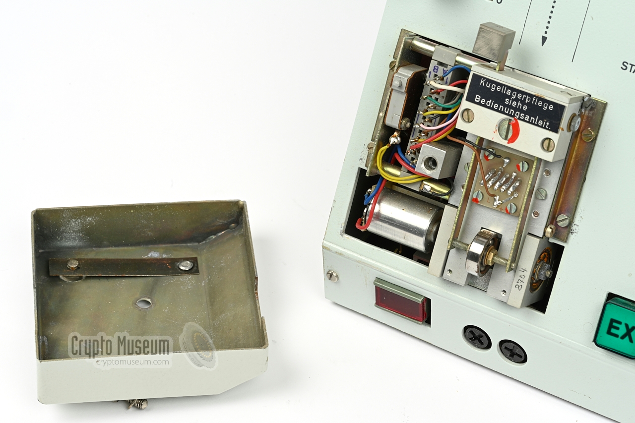
The next problem to address was the tape reader
at the front left of the device. Although it was in a
cosmetically good condition,
it didn't run when the the tape-feed button was pressed.
A closer inspection told us that the motor wanted to run
– it was running hot – but was somehow blocked.
|
After removing the tape reader from the front panel, it became clear
that the ball bearings at both sides of the rubber pressure roller –
which resides under the paper path – were rusty and were binding.
It appears that the device had caught some water drops at some
point in its life, which had not been treated appropriately.
The motor was temporarily removed, after which the ball bearings were
treated with a derusting agent, penetrating oil, a quick drying cleaner
and alcohol. Finally, the bearings were regreased and the small motor
was mounted back in place.
|
|
|
|
After refitting the tape reader to the front panel, the unit was tested.
Pressing the tape-feed button turns the motor on and feeds the paper at
high speed. In addition, a message could be loaded by installing a tape,
pressing the INP(UT) button and answering 'Y' to the question TR?.
|
At this point, the only remaining problem was the reconstruction of the
sound module. This required the development of a printed circuit board
(PCB) that could hold one or more EPROMs with the sound samples for a
specific language.
Although a single board is sufficient for German, other languages, such as
Spanish, may require an extra card to be used. As modern EPROMs are
generally larger than the old 2764 devices used on the original speech card,
we decided to use a single 27C020 on each card, so that we could store up
to four languages in a single module.
|
|
|
An extra difficulty was the fact that the backplane requires the use of a
specific 58-pin connector that was only made in the former DDR and a metal
frame that was used in early DDR computers. Luckily, there were some very
kind people on the Robotron Forum who were able to help us out.
Our 32620 is now fully operational again and can play out
messages in 4 languages plus morse.
➤ Description of the reproduction speech module
|
|
-
A supercap is a good alternative for a rechargeable NiCd battery,
especially in low-current applications like powering CMOS SRAM
chips. The supercap used here, has a capacity of 1.5 Farad, which is
sufficient for retaining a message for at least several weeks.
Unlike batteries, supercaps do not leak.
-
When designing digital circuits, it is good practice to connect a
100nF decoupling capacitor from the +V to ground, as close to the
IC as possible. In the early days of digital design, these 100nF
capacitors were often omitted, as a result of which circuits could
become unstable and unreliable.
|
Error 15 (speech module missing) Second row of pixels missing from display Device 'freezes' after several hours of use Arrow symbols missing from next/previous buttons Backup battery worn out and leaking Electrolytic capacitors worn out Unresponsive keys on keypad Tape reader motor not working (running hot)
|
- Broken EFS-58 connector at rear end of expansion board repaired.
- 2nd pixel row of display fixed: R10 (22k) on board _1.12 replaced.
- Arrow symbols added to next/previous buttons.
- Backup battery swapped for 1.5F/10V supercap.
- Electrolytic capacitor swapped on Relay board.
- All electrolytic capacitors swapped on CPU board.
- All electrolytic capacitors swapped in PSU.
- 6 buttons of the keypad removed, disassembled, cleaned and refitted.
- Tape reader repaired and greased.
- Output cable KS-51 — XLR added.
- Speech cartridge reconstructed.
- Broken speech samples in ROM repaired.
|
|
All connections of the 32620 are located at the rear panel. There are sockets
for connection of an external speaker, transmission line (Leitung) and
serial port (RS232).
There is also an expansion socket (Bu1) for driving external equipment and
for responding to external events.
Below is the pinout of the sockets, as seen when looking into the sockets
from the rear of the device.
|
|
The line output of the device is available on a 5-pin screw socket at the rear
of the device. This socket is similar (but not identical) to a 5-pin DIN socket.
It accepts RFT plug KS 51 with external thread (type 063-01:00), a.k.a.
TGL 31428. Below is the pinout when looking into the socket.
|
- Line out (A)
- unused
- Line out (B)
- unused
- unused
|
|
|
Also at the rear is a 6-pin military socket on which a serial port
is available. The port is driven by the SIO on the CPU board,
and can be synchronous as well as asynchronous. In the latter case,
no hardware handshaking is used. Below is the pinout when looking
into the socket.
|
- Clock
- TX Data
- unused
- GND (0V)
- unused
- RX Data
|
|
|
|
External switchboard
Bu 1
|
|
|
|
At the rear is a 26-pin socket for controlling external equipment
and for driving the 32620 from external events. The socket is an
EFS26 AB female part. The upper nine rows (1-9) are connected to
the isolated contacts of three internal relays (rs 1, 2, 3).
The lower four rows (10-13) are for the external inputs. Below is
the layout when looking into the socket from the rear of the device.
|
A: rs 2/2 n.o. 4 B: rs 2/1 n.c. 4 A: rs 2/2 n.c. 4 B: rs 2/1 n.o. 4 A: rs 2/1 common 4 B: rs 2/2 common 4 A: rs 1 n.o 3 B: rs 3/1 common 4 A: rs 1 common 3 B: rs 3/2 n.o. 5 A: unused B: rs 3/2 n.c. 5 A: unused B: rs 3/1 n.c. 5 A: unused B: rs 3/1 n.o. 5 A: unused B: rs 3/2 n.o. 5 A: Remote 1 B: GND A: Latched 2 B: GND A: STA/STP1 B: STA/STP2 A: OUT1 B: OUT2
n.o. = normally open, n.c. = normally closed
|
|
-
Remote start/stop input (active high).
-
When connected to GND (active low).
-
RS1 = Morse output.
-
RS2 = Running.
-
RS3 = END.
|
Device Speech/morse generator Purpose Transmission of coded messages in speech or morse on OWVL Developer Institut für Kosmosforschung Manufacturer ZWG Berlin (Germany) Model 32620, 32620.2 Country East-Germany (DDR) Years 1982-1987 Predecessor Device 32028 (Sxhnatterinchen) Customers MfS, Warsaw Pact Memory 3791 characters (including spaces) Backup Internal 2.4V NiCd battery Morse Tone or relay contact Tone 800, 1000 or 1200 Hz Speech 2 x 48kB (max. 13 words, 16 seconds) Speed 30 to 240 characters per minute (morse) in 10 steps
70 - 110 words per minute (speech) Pitch 0%, -10%, +10% Input 5-level paper tape (ITA-2) (CCITT-2)
Manual (via keybord)
RS232 serial port (modem) Output Audio 600Ω 0 - +6dB (adjustable)
Relay contact (morse only)
Internal speaker
External speaker Speaker 500mW into 6Ω Remote STA/STP, OUT Serial Synchronous or asynchronous (RS232) serial port Mains 110, 127 or 220V AC (switchable), 22 Watt Battery 12V DC, 2A Temperature +5 to +40°C Storage 0 to +55°C Humidity 90% (max.) Dimensions 290 x 260 x 135 mm Weight 7.1 kg
|
|
Although the device was officially designated 2620 (later: 32620)
(i.e. the Stasi project number) 1 it was known by
its users under various names, the most common of which are listed below.
|
Gerät 2620 Device 2620 Gerät 32620 Device 32620 Sprach-Morse-Generator Speech-Morse-Generator Stimme Voice Eiserne Frau Iron lady Kluge Frau Clever lady Schlaue Frau Smart lady
|
-
When the development of the device was initiated in the late 1970s,
it was given the Stasi project number 2620. This number was later
prefixed with a '3', which is the last digit of Stasi department
Abteilung 33.
➤ More about Stasi project numbers
|
|
Below is an non-exhaustive list of model and serial numbers of 32620
devices that may help to determine how many units were manufactured.
It is likely that the first two digits of the serial number represent
the year of manufacturing.
Please report any devices that are not listed here.
The model, version and serial number are printed inside the
hinged lid at the rear.
➤ Contact us
|
3 2620 8401 1984 Oct ? 3 2620.2 8402 1984 Oct Private collector (Australia) 3 2620 8409 1984 ? 3 2620 8410 1984 ? 3 2620 8414 1984 ? 3 2620 8415 1984 ?
3 2620 8501 1985 Nov ? 3 2620 8515 1985 Nov Spionagemuseum Berlin (Germany)
3 2620.2 8704 1987 Feb Crypto Museum (Netherlands) 3 2620.2 8729 1987 Feb Private collector (Germany) 3 2620.2 8732 1987 Feb ?
|
The first batch (serial numbers 8401 to 8415) was used at the
Institut für Kosmosforschung (Space Research Institute)
— the developers of the device — for testing [2][7].
From this list is is clear that there were at least three production
batches: in 1984, 1985 and 1987 respectively. It is also known that
additional units were ordered in 1989. If each production batch
consisted of 50 units, it is likely that between 150 and 200 units
were manufactured.
|
|
Please note that there are two versions of the device: 32620 and 32620.2.
The EPROMs of these two versions are not interchangable. Also note that the
original EPROMs are pretty old now (40+ years) and that EPROMs from Eastern-Bloc
production may not be as good as EPROMs from western manufacturers. It is
therefore possible, if not likely, that part of the EPROM contents may have
been damaged. We therefore had to combine the firmware from several sources, and
occasionally had to repair certain memory locations manually. These are identified
as '(better)'.
|
|
The first version (32620) is from 1982 and uses two system EPROMs: one on
the CPU board and one on the expansion board. These are 2716 (2KB) or
2732 (4KB) types.
Furthermore, the
speech board has room for six 2764 EPROMs (8KB), which is sufficient for the
German language, but not for Spanish which requires 8 such EPROMs.
|
|
The boards of the second version of the device
(32620.2) are completely different. There is only one system EPROM,
which is a 2764 (8KB). It is likely that it contains the contents of both
former system EPROMs (from the CPU board and the expansion board).
The speech module has been enhanced to accomodate two boards
with six 2764 EPROMs each, which is sufficient for Spanish.
|
-
Improved version in which glitches in the sound samples have been repaired.
-
Recreated at Crypto Museum from surviving recordings.
|
-
Document from BStU archives [7], kindly supplied by Detlev Vreisleben [2].
-
In the handwritten draft, the device is identified as 32026, which is clearly
wrong and should be 32620.
|
- Anonymous donor, Device 32620.2 - THANKS !
Crypto Museum, July 2017.
- Detlev Vreisleben, Personal correspondence
July 2017 — November 2023.
- Operativ-Technische Sektor, Abteilung 33, Leistungsplan 1990 fuer die KST: 3360 2
VVS B77-89, 14 October 1989. Pages 1 and 7.
- Anonymous, Letter from East-German female 'numbers speaker'
30 January 2010.
- Bundesbeauftragte für die Stasi-Unterlagen (BStU) 1
Federal Commissioner for the Stasi-Records.
- Peter Staal, YouTube channel
Retrieved July 2017.
- Jorg Drobick, YouTube channel
Retrieved July 2017.
- Karsten Hansky, Sound samples of current Numbers Stations
Received August 2015 - September 2019. Many thanks!
- Wikipedia, U880
Retrieved December 2021.
- Jörg Drobick, Personal correspondence
21 May 2024.
|
|
-
Full name: Bundesbeauftragte für die Unterlagen des Staatssicherheitsdienstes
der ehemaligen Deutschen Demokratischen Republik
(DDR) —
Federal Commissioner for the Records of the
State Security Service
of the former German Democratic Republic (GDR) —
officially abbreviated BStU.
-
Document from BStU archives [5], kindly provided by Detlev Vreisleben [2].
|
|
|
|
Any links shown in red are currently unavailable.
If you like the information on this website, why not make a donation?
© Crypto Museum. Created: Wednesday 19 July 2017. Last changed: Thursday, 20 November 2025 - 10:05 CET.
|
|

|
|
|
|


![Piles of 32620 devices waiting to be scrapped just after the Fall of the Berlin Wall (around 1990). Photograph provided by BStU [5] via Detlev Vreisleben [2].](img/32620_wende_large.jpg)


