|
|
|
|
|

|
|
WWII RX NL Oranje
Clandestine midget receiver · Radio Oranje
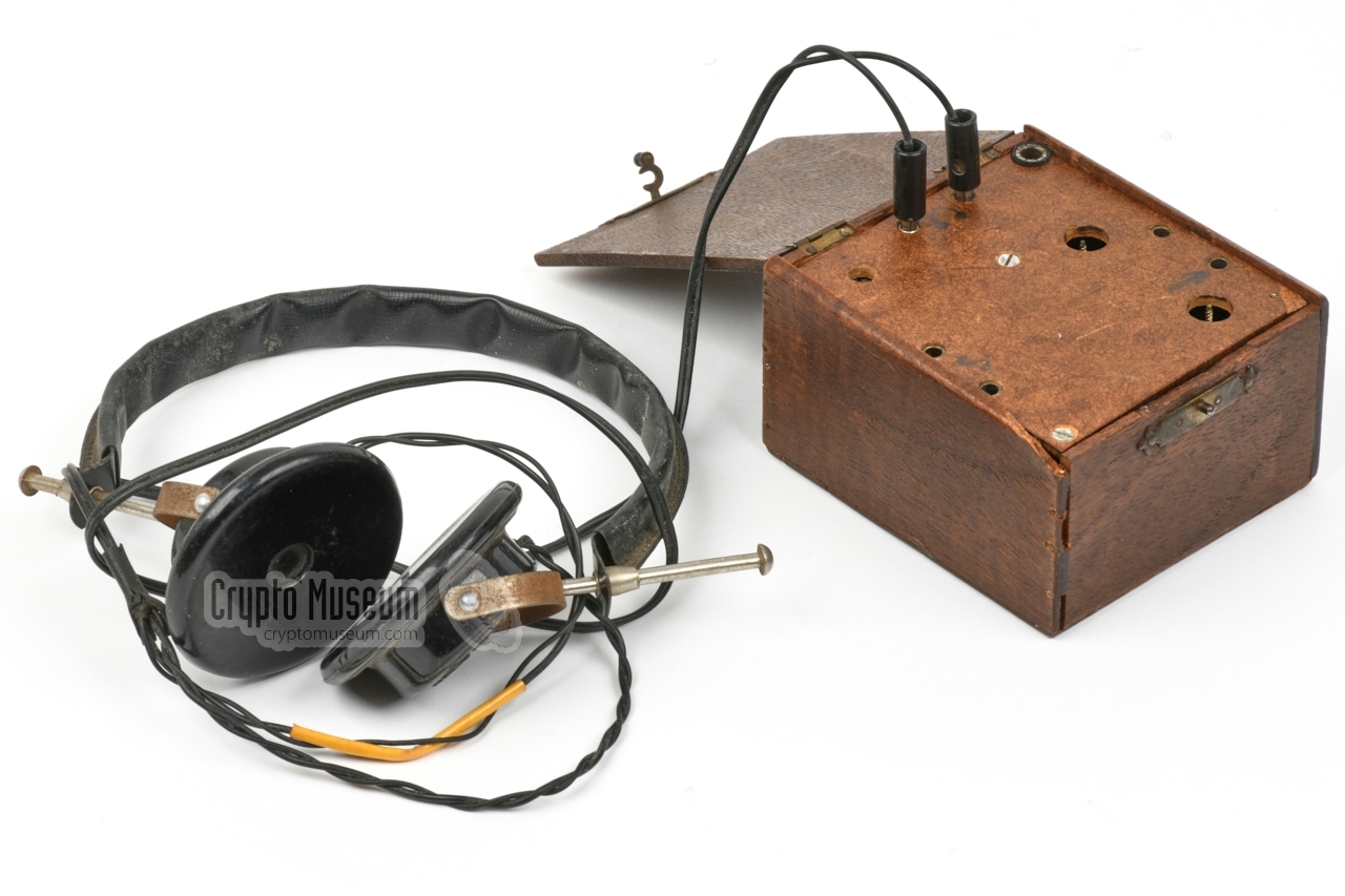
The clandestine miniature receiver 1 shown below, was built secretly
in The Netherlands during World War II (WWII),
at a time when the possession of a radio was declared
illegal. It was used to listen to the broadcasts of the British BBC in the short wave (SW) 31 and 41 meter band (on 9677 and 7137 kHz), and in
particular to the broadcasts of Radio Oranje (Radio Orange),
a 15 minute news program in the Dutch language,
under control of the Dutch Government in exile in London.
|
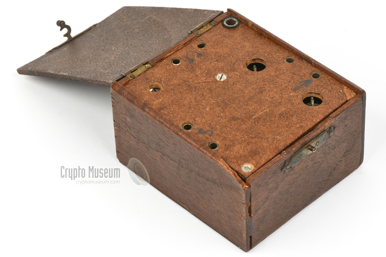
The radio measures 110 x 93 x 60 mm and weighs 678 grams
(transformer included).
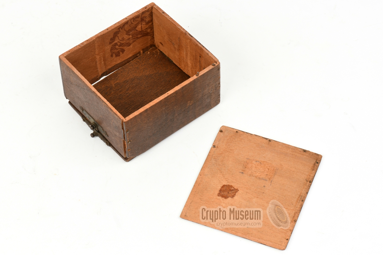
It is disguised as a woman's jewelry box, made
from an old modified cigar box. The sides are glued together and are
enforced with tiny nails. At the top is a hinged lid that has a
lock at the front.
Opening the lid reveals a hardboard top panel
with recessed tuning and
feedback controls, and sockets for connection of headphones,
antenna, ground and 220V AC mains power. Unlike other designs of
Radio Oranje receivers, it
can not be powered by a battery or by a 6V bicycle dynamo.
|
|
|
-
As this receiver was built by a Philips employee during WWII,
it does not have a name or a model number. Because it is built around three
'acorn' type valves,
we have nicknamed it 'Acorn receiver'.
-
Also known as a TRF receiver.
-
Although he never was a licenced amateur radio operator, Chris Visman
was one of the driving forces of the Eindhoven branch of the VERON,
from 1945 until his death in 1999.
|
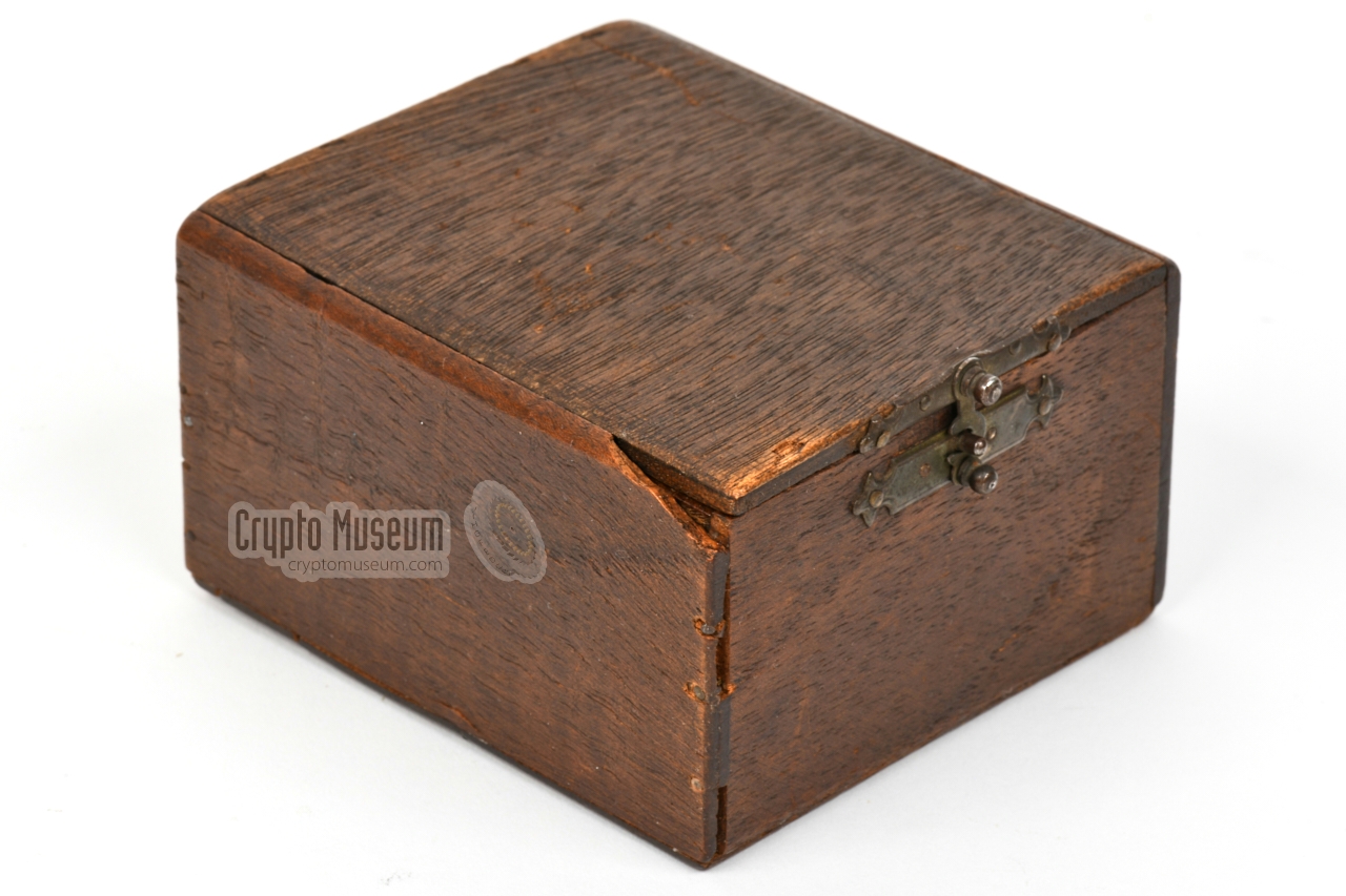
Below is an overview of the features of the receiver. When the
case is closed,
there is no visible hint that a secret receiver might be hidden inside.
It seems to be made from dark oak wood, and
fits perfectly in a lady's wardrobe without attracting any attention when
the house is searched.
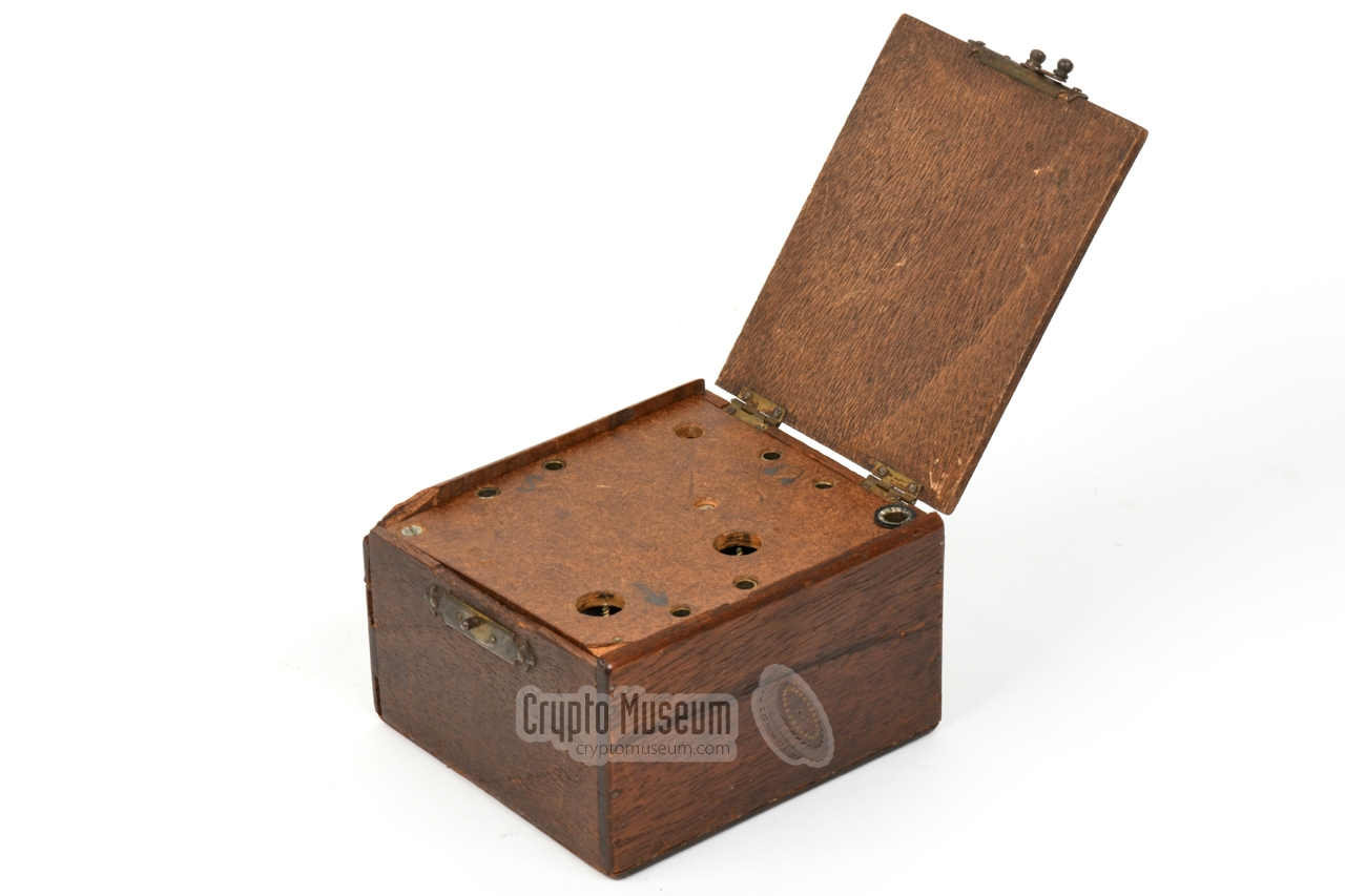
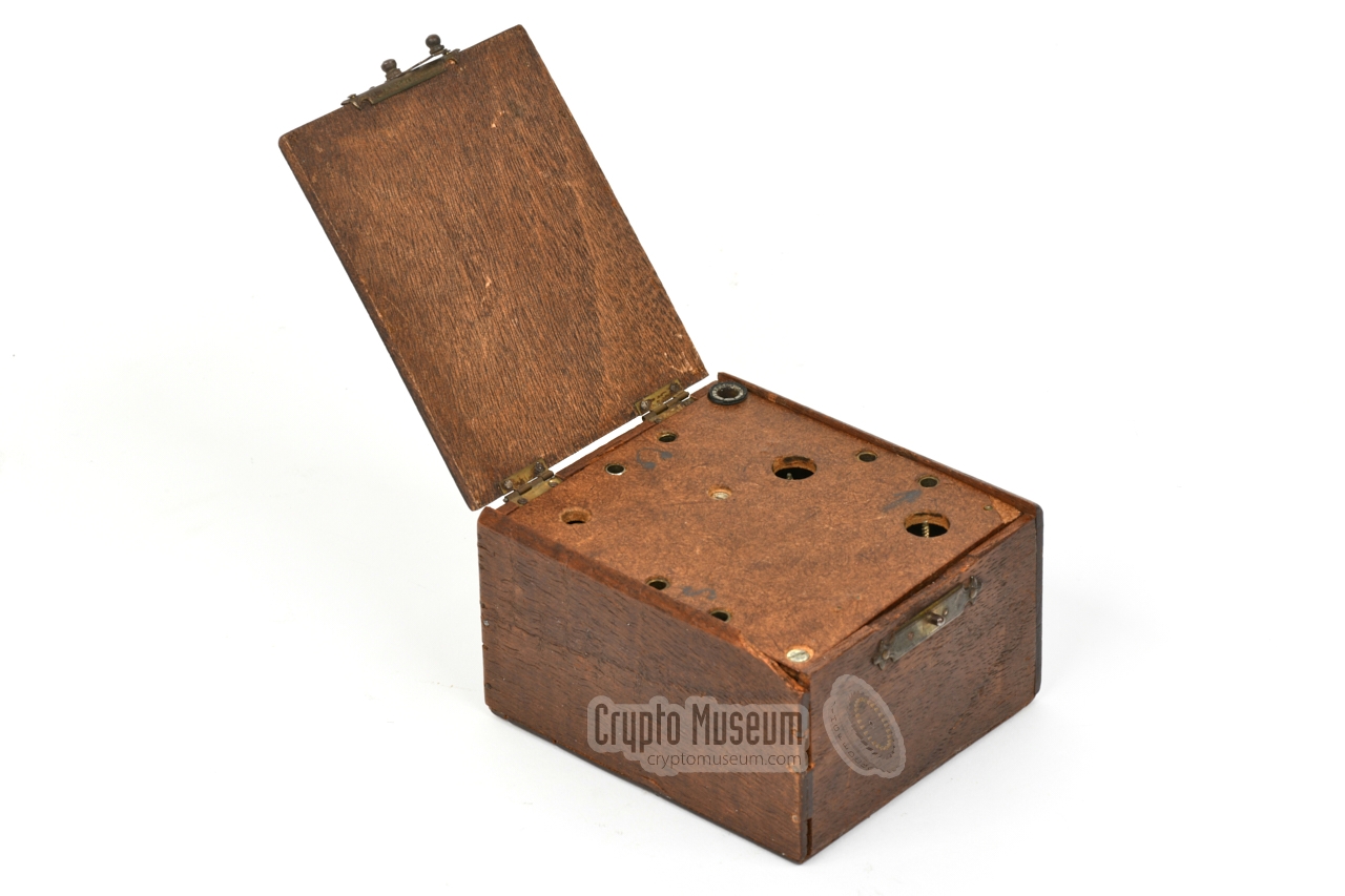
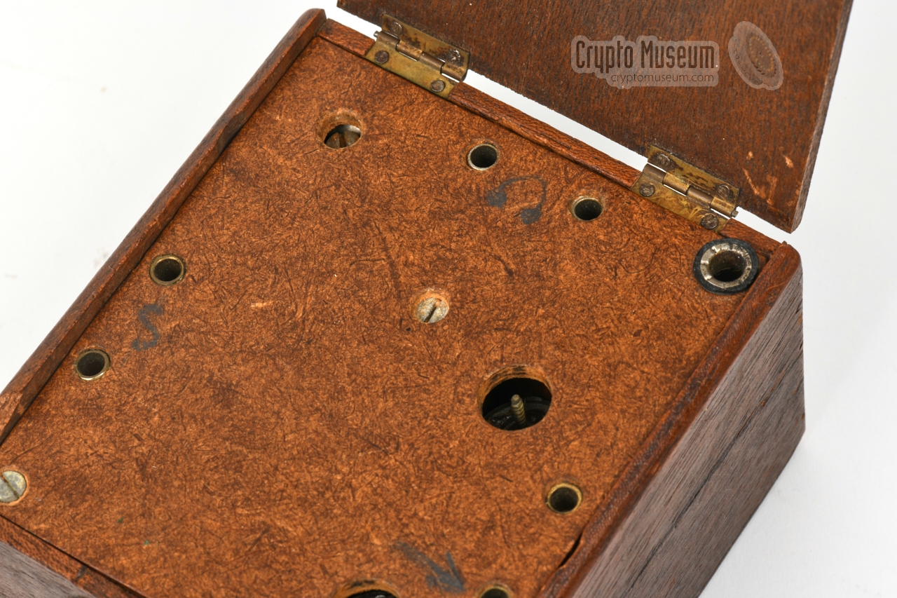
But hidden below the lid is the control panel.
It has banana sockets at the edges and three recessed controls.
The two terminals at the left should be connected to the mains,
but this is potentially dangerous. Always connect the power cord to the
receiver first, before connecting it to the mains socket.
The device is switched ON by turning the regeneration control clockwise.
A pair of 4000Ω headphones
is connected to the terminals at the top. Ground and antenna are connected
to the sockets at the right. When searching for a station, the two trimmers
should be adjusted with a special tool, whilst the regeneration control can be
adjusted with a regular screwdriver. The socket in the upper right corner
is connected to the rightmost headphones socket and carries the 110V HT
voltage. The reason for the presence of the this socket is currently unknown,
but it is possible that it was used as a safety ground as the headphones
also carry the HT voltage.
|
At the outbreak of WWII, the Dutch Government
and Queen Wilhelmina, were relocated to London (UK), from where they
controlled resistance activities and information gathering. To give some
comfort to the Dutch population, and to counter the German propaganda,
the Dutch Government had arranged a nightly 15 minute program on the
channels of the BBC World Service.
The broadcasts were known as Radio Oranje,
and sometimes contained coded
messages for the resistance.
Under the German occupation it was illegal
in the Netherlands to listen to
foreign radio stations, especially those of the BBC and
Radio Oranje.
People were only allowed to listed to the German propaganda stations.
When the Germans discovered that the Dutch clandestinely listed to the
BBC, they started jamming the transmissions by means of a
nationwide network of jammers.
When this didn't help — people developed
jammer-eliminators —
the Germans made it illegal to possess a radio from 13 May 1943
onwards. Houses were searched regularly, and when a radio was discovered,
the house owner risked a high fine, or in some cases even the death penalty.
People who had more than one radio, often held one back to covertly listen
to the BBC, but they were generally large and were difficult
to hide. In case of a razzia, they were easily discovered.
For this reason, engineers from two of the largest radio factories in
the country – Philips and its subsidary
NSF – covertly started building a range of Radio Oranje receivers,
using any parts that were available. In addition,
radio amateurs 1
throughout the country started building their own miniature covert radios
from clandestinely obtained parts. Most of these radios are of the so-called
reflex type, and are commonly built around two miniature 'acorn' valves
made by Philips.
The receiver featured here is slightly different, in that it is built with
three 4672 'acorn' pentodes and one EA50 miniature diode.
The pentodes are used for an RF pre-amplifier, a regenerative detector
and an AF amplifier, whilst the diode is used as HT rectifier.
It was built during WWII by Chris Visman – an employee of
Philips
in Eindhoven – from clandestinely obtained components.
|
 |
-
At the beginning of the war, the Netherlands had approx. 400
licenced amateur radio operators.
In addition there were many hobbyists and enthusiasts
who were also able to build their own radio.
|
Below is the circuit diagram of the receiver, taken down from the actual device.
Unlike other Radio Oranje receivers, which were commonly two-valve
reflex circuits, the one shown here is a three-valve
receiver, built with E1F (4672) miniature 'Acorn' valves.
It consists of an RF stage (V1), a regenerative detector 1 (V2) and an AF amplifier (V3).
A pair of headphones should be connected to the two terminals
at the right. They are connected in series with the anode (and g2) of V3.
The reception frequency is tuned with C4, whilst C2 should be tuned for
maximum signal. Potentiometer R6 is the regeneration control.
There is no volume control. The advantage of a regenerative receiver is
the high sensitivity with relatively few components. The disadvantage is
that the regeneration control has to be re-adjusted continuously when
changing the frequency.
Another disadvantage is that V2 will be close to oscillation when the
optimum setting is found, which means that the device emanates RF
energy that causes interference in nearby receivers.
In other words: with the right equipment, it can be detected from some
distance.
In the receiver shown here, this effect is reduced by the application of
a separate RF pre-amplifier (V1).
The device is powered by a built-in 220V mains transformer. It is has
three secondary windings: 90V for the HT voltage, 6.3V for the filaments
of the valves (LT) and another 6.3V 2 for the filament of the EA50 diode valve (V4).
The EA50 (V4) is used here as a rectifier for the HT voltage. A short antenna
and a suitable ground (earth) should be connected to the terminals at the
left.
The circuit is very similar to the OD receiver – another
Philips design – that was used during WWII by the Dutch clandestine
resistance organisation Oredienst (OD) for a
national underground radio network. It was activated on 5 September 1944,
when the Allies had entered the Netherlands.
|
|
-
Regeneration is also known as positive feedback.
-
Reduced to 6V by means of a wire-wound resistor.
|
|
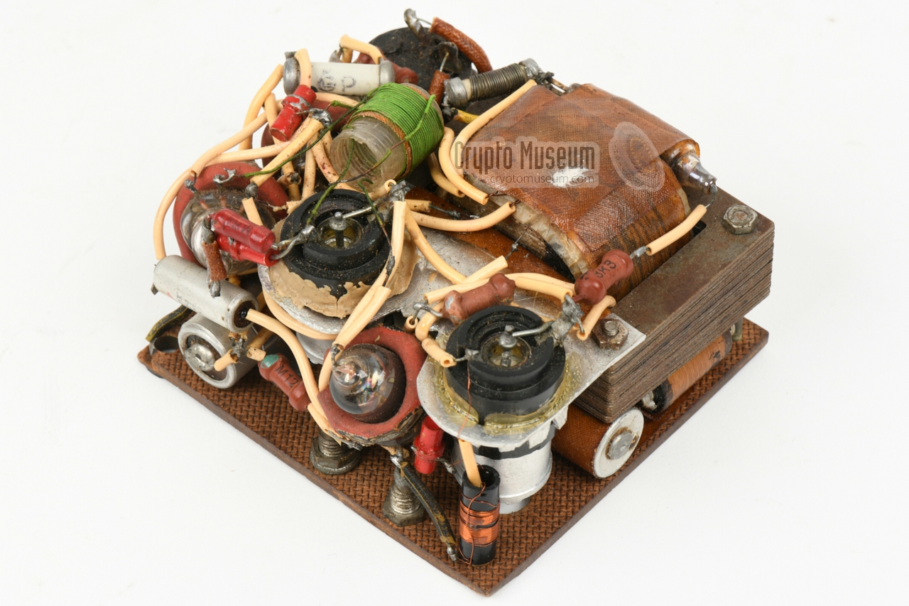
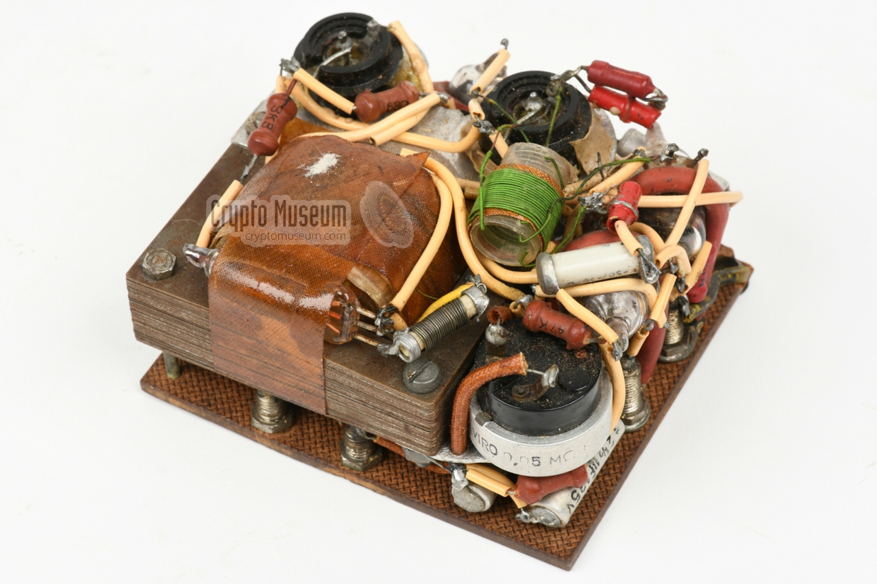
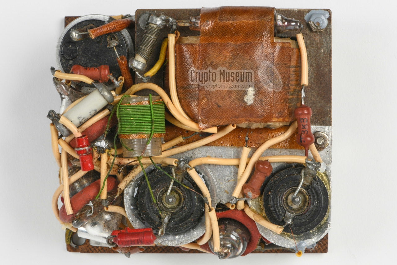
The interior of the three-valve receiver can be accessed by opening
the top lid and holding the case upside down (carefully),
after which the entire assembly comes out.
All parts are mounted to the reverse side of the
hardboard top panel, that is 4 mm thick and measures 94 x 84 mm.
|
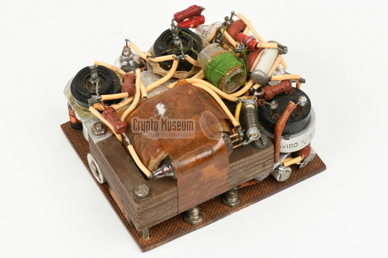
About 50% of the space is taken by the mains transformer, which is
bolted to a corner of the top panel. An aluminium frame,
bolted to the transformer, holds the two
variable capacitors
(large beehive trimmers) 1 that are accessible through
two large holes in
the top panel.
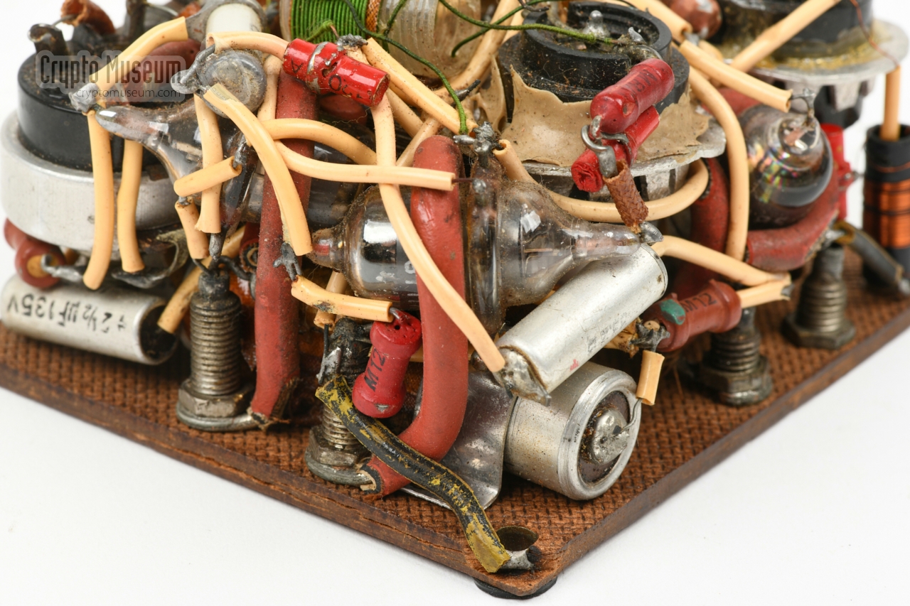
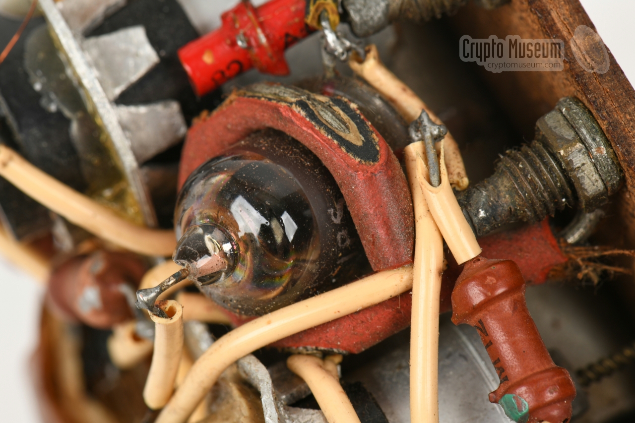
The three acorn valves are held by
makeshift rubber-covered metal brackets
that are held in place by the banana sockets, as shown in the image on the
right. As the valves have contacts
at all sides, the wiring of the receiver is rather cluttered and covers
most of the other parts.
|
|
|
|
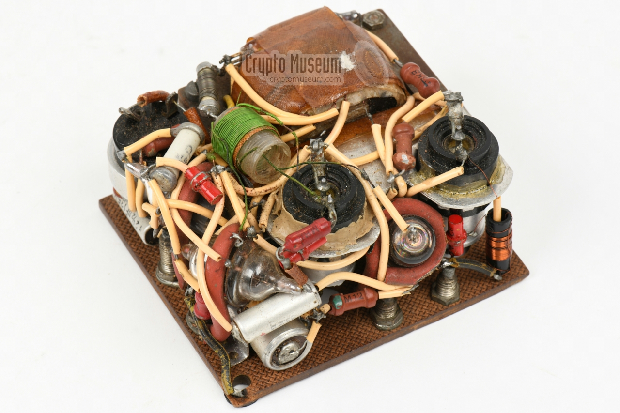
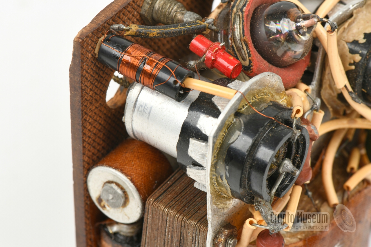
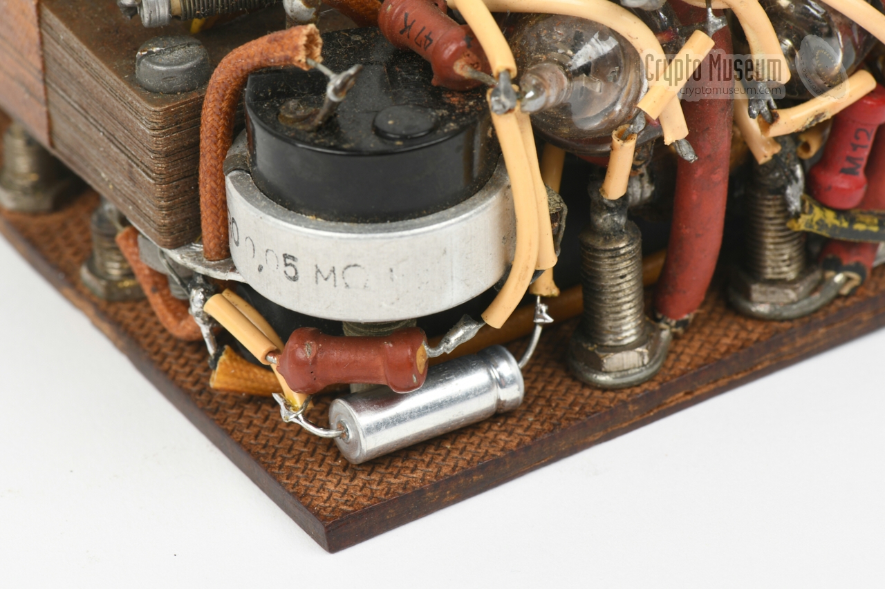
In one of the other corners
of the hardboard panel is a potentiometer (R5)
that can be adjusted with a screwdriver through a hole in the top panel.
The ON/OFF switch is mounted to the rear end of the potentiometer and
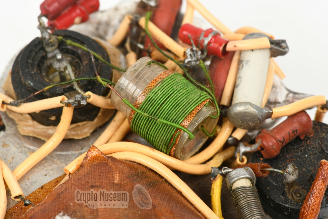
is controlled by the same axle. At the centre is the
green detector coil
(L3/L4) which is wired to the anode circuit of V1 and to the cathode and
g1 circuits of V2. As the green coil sticks out somewhat, the bottom panel
of the enclosure is modified to accomodate it.
|
-
In Dutch known as tol trimmers.
|
|
When we obtained the receiver it was uncertain whether it would ever work
again as it had several loose wires, probably caused by frequently handling the
object in the years after the war. For this reason we decided to take down the
circuit diagram
first, so that a potential repair attempt might be more
successful.
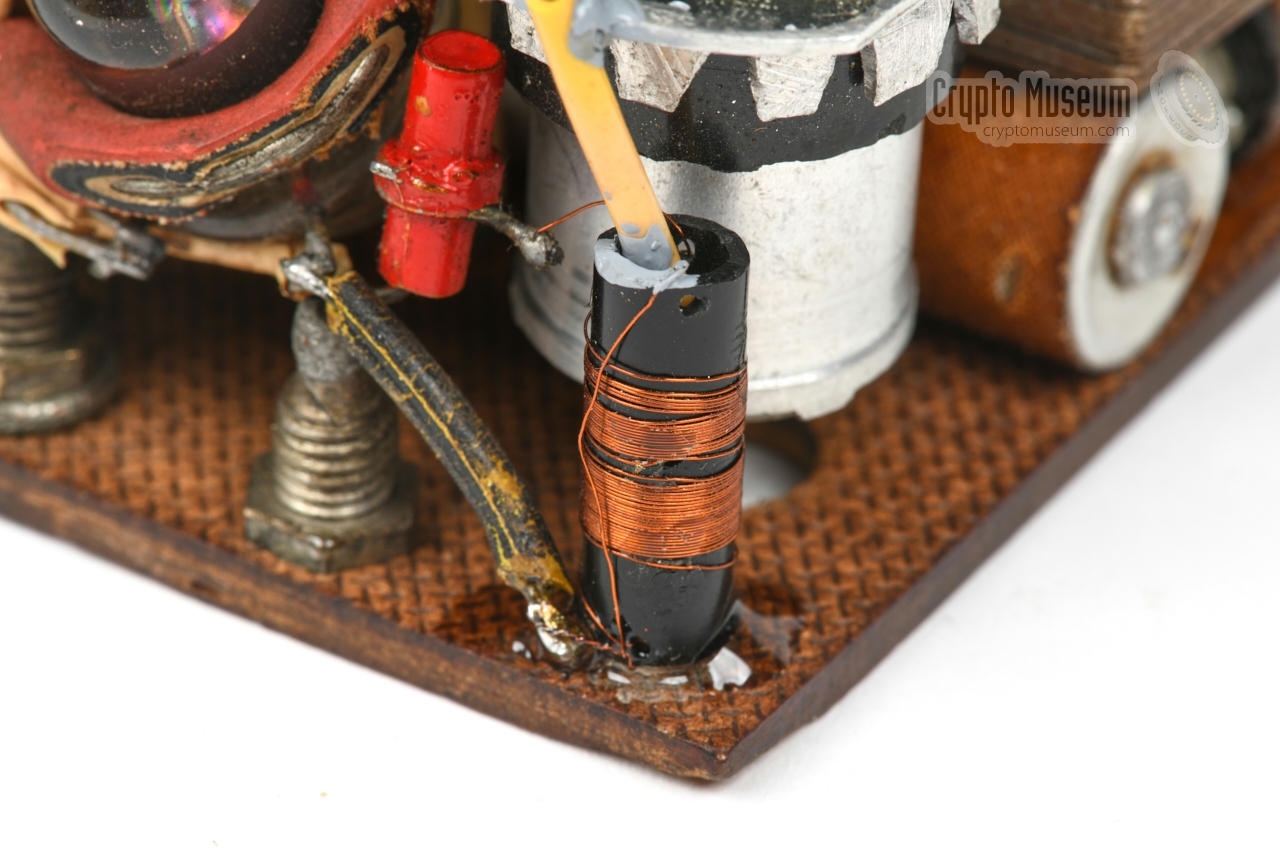
Whilst doing this, it was noticed that the small antenna coil – fitted in
one of the corners of the hardboard panel –
was loose and had a broken connection at the ground side.
|
The antenna coil was fixated
and the ground connection was restored.
Next, the two loose wires of the detector coil – shown in the image on the
right – were re-fitted to the right joints.
The two large beehive trimmers were also loose
and had apparently been re-glued in an earlier repair attempt.
The old glue was carefully removed and replaced by a modern alternative.
When we were certain that the internal wiring was intact,
we gradually raised the mains voltage from 50 to 220V AC by means of a VARIAC.
|
|
|
|
This is done to allow the electrolytic capacitors to reform themselves,
as otherwise they might explode.
After a short while,
the headphones produced a strong 50 Hz hum, indicating that (some of the)
circuit was working, but that the capacitors had probably lost their
capacity.
|
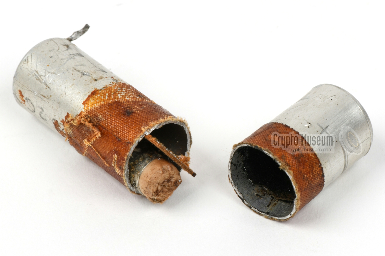
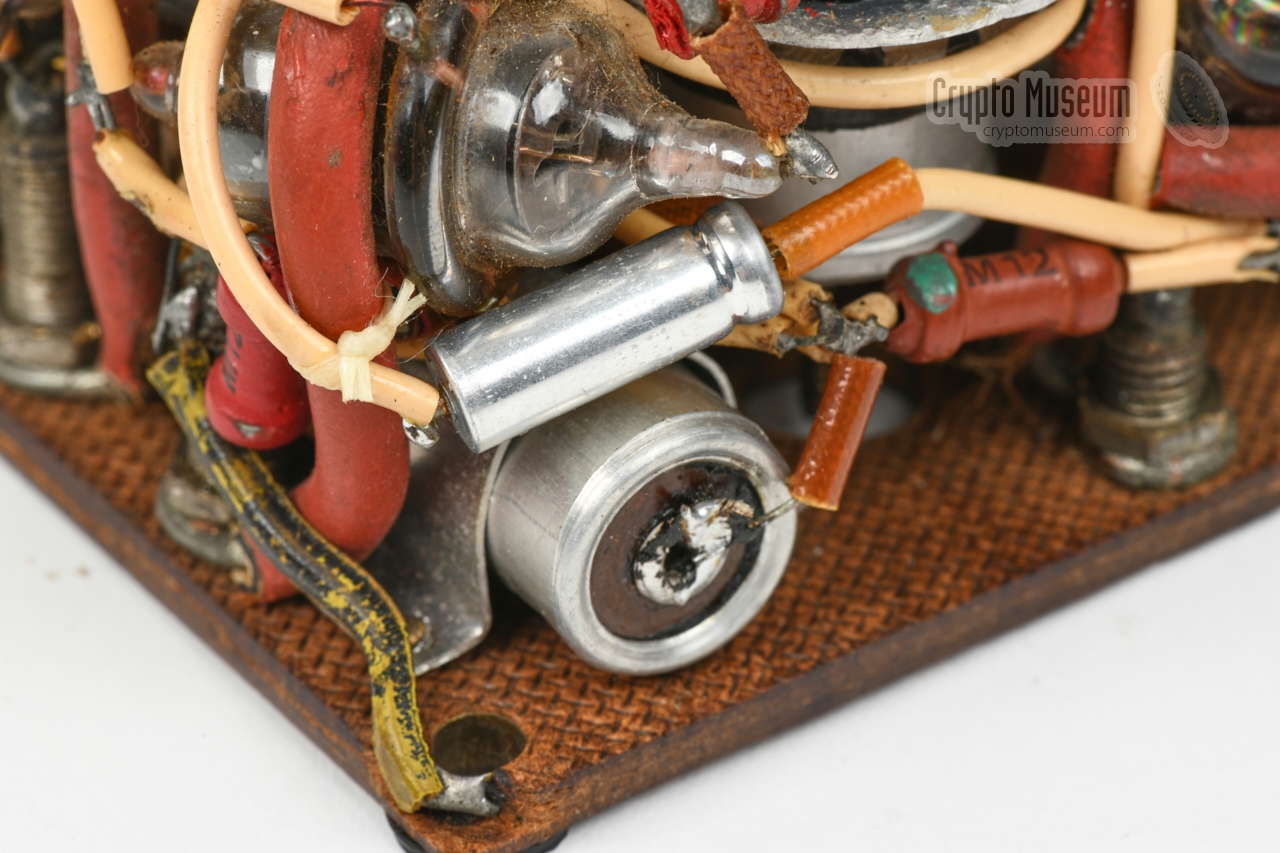
This was indeed the case. The two large 6µF capacitors each had no more
than 200pF left. One of these capacitors could not be removed without damaging
the receiver, so it was left in place. The other capacitor could be removed,
but was so prominently visible, that we decided to use it as an enclosure for
2 modern alternatives.
The inside of the original 6µF capacitor is visible in the image on the right,
and shows that it is completely dried out. All electrolyte is gone. As modern
capacitors are smaller, we managed to fit both capacitors in one of the old
enclosures.
|
|
|
The remaining three 2.5µF capacitors were also removed (again, no capacity)
and were replaced by 'naked' modern alternatives.
After applying the 220V AC mains voltage again, the receiver came to life and
produced a soft noise, which could be increased by turning
potentiometer R6.
The antenna input was then sweeped with a signal generator, to
determine the frequency range.
The following restorations were carried out:
|
Below is a YouTube video in which a Radio Oranje receiver is
properly demonstrated. The design of the radio is slightly different
from the one featured above, but the principle is the same.
It shows how the radios were used covertly during WWII, and
how they were powered when the mains network was down, using
a bicycle and a running water tap as alternative power sources.
|
|
E1F (4672) is a pentode in so-called 'Acorn' shape, made by
Philips
in Eindhoven (Netherlands) and
Mullard Electronics in the UK.
It was introduced in 1936 and is equivalent to the
954 made in the US by RCA,
Raytheon and Tungsol. In the receiver featured here, it is used
in all three stages.
|
|
EA50 was a popular miniature diode valve, introduced in 1939
and manufactured by
Philips in Eindhoven
(Netherlands) and
Mullard Electronics in the UK.
In the receiver featured here, it is used as a rectifier for
the HT voltage. The EA50 is also known as CV1092.
|
Design Philips (or Philips employee) Manufacturer Philips employee Chris Visman Year 1942/44 (est.) Type TRF, regenerative detector Valves 3 x E1F, 1 x EA50 Frequency SW 31 and 41 m (7100 - 9700 kHz) AF Output High impedance headphones, 4000Ω (isolated) Power 220V AC mains Dimensions 110 x 93 x 60 mm Weight 678 g
|
|
|
|
Any links shown in red are currently unavailable.
If you like the information on this website, why not make a donation?
© Crypto Museum. Created: Monday 04 January 2021. Last changed: Wednesday, 05 November 2025 - 12:08 CET.
|
|

|
|
|