|
|
|
|
|

|
|
WWII UK OD SBO Paraset Mk XV → ← Mk V
WWII clandestine spy radio set
The Whaddon Mk VII (Mark 7), also known as Paraset, 1
is a valve-based, lightweight,
short-wave, CW-only clandestine transceiver
or spy radio set, for the 40 and 80 metre radio bands,
introduced in late-1942 by Section VIII of the the British
Secret Intelligence Service (SIS (MI6),
at Whaddon Hall and Little Horwood (UK).
It was used throughout WWII
by SIS (MI6) agents and intelligence gathering resistance
organisations, and was dropped by parachute over German-occupied
European countries,
in particular in Belgium, France,
The Netherlands and Norway [2].
|
The Mk VII was small, lightweight and very easy to operate, but had
several disadvantages. Its valves are not permanently installed,
and have to be removed
– and stowed inside the top cover –
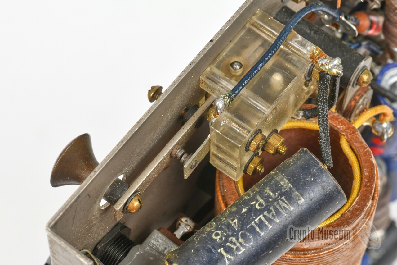
before the case can be closed. Furthermore, it can only
be operated in CW (morse) with the
small internal morse key at the front right.
There is no provision for an external morse key. 2
As the device has no sidetone provision either,
you can't hear your own morse code when transmitting.
But the major – and potentionally lethal – issue during WWII, is the fact
that the self-regenerative receiver unknowingly becomes a transmitter when the
regenerate control is used incorrectly.
This unwanted RF signal can be traced from some distance by means of
radio direction finding (RDF), even when the device is not
in transmit mode.
Not knowing that the Germans actively exploited this mis-feature,
many agents lost their lives as a result of it.
This was particularly the case in major urban areas, where the Germans
deployed many direction finding vehicles, but less so in distant rural areas.
In the latter part of the war,
the Paraset was therefore mainly used in Norway.
After WWII, in the early stages of the Cold War,
some Parasets were briefly (re)used by the newly established
Stay-Behind Organisations
of several European countries, including The Netherlands,
until they were replaced by better modern alternatives of domestic or
American manufacture.
|
 |
-
The nickname Paraset is probably incorrect. It was introduced in the
early 1970s by Pierre Lorain [8] at a time when most information was still
classified, and is based on incorrect assumptions [9][10]. Nevertheless we
will use the name Paraset throughout this page, as it is commonly used by
collectors and radio amateurs today.
The actual Paraset – La Paracette – was the
British Mk V, which was first dropped over France in 1941.
-
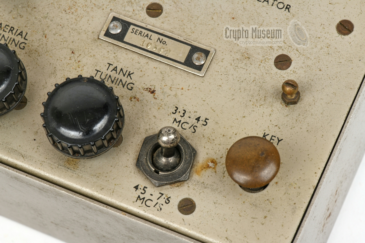
There are Parasets with a socket for an external morse key – located to the
right of the internal key – such as S/N 10313, but it is unknown whether this
is an original feature or an aftermarket modification [5].
|
WARNING —
The Paraset is one of the rarest spy radio sets of WWII. Very few have
survived. It is also one of the most popular designs for replicas, probably
because of its aestetics and the simplicity of its circuits [4].
With so many reproductions and so few real devices, collectors and museums
should be careful when obtaining one.
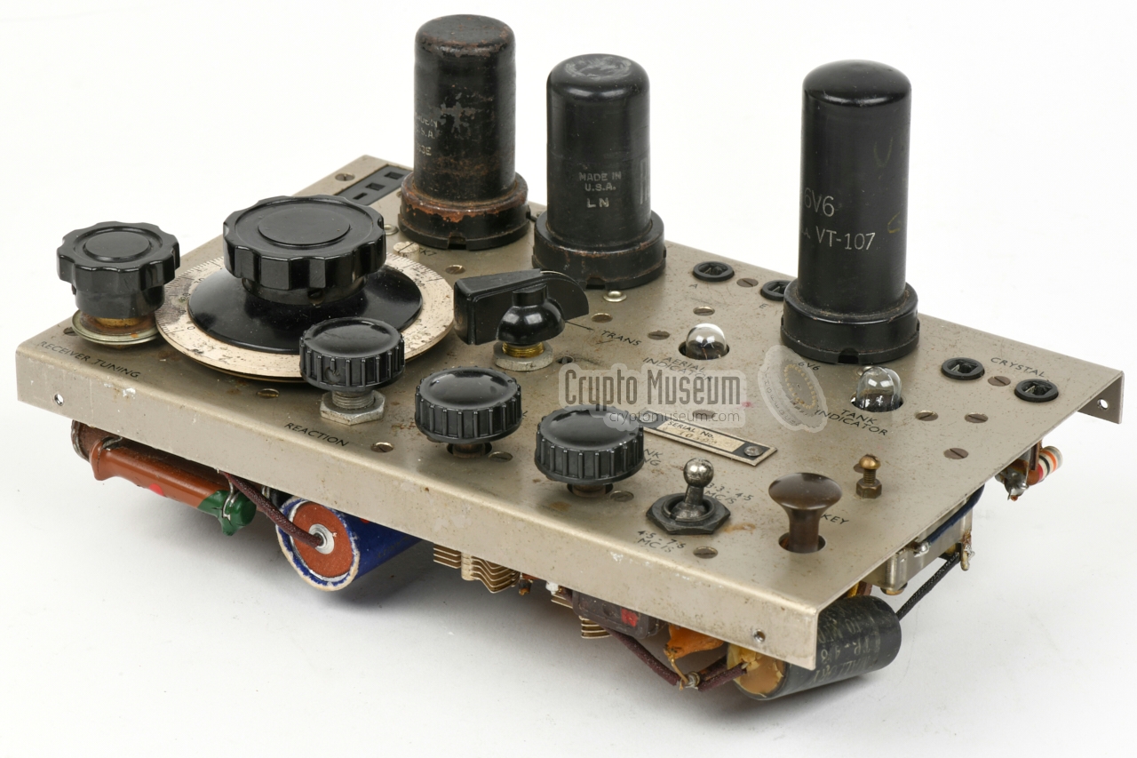
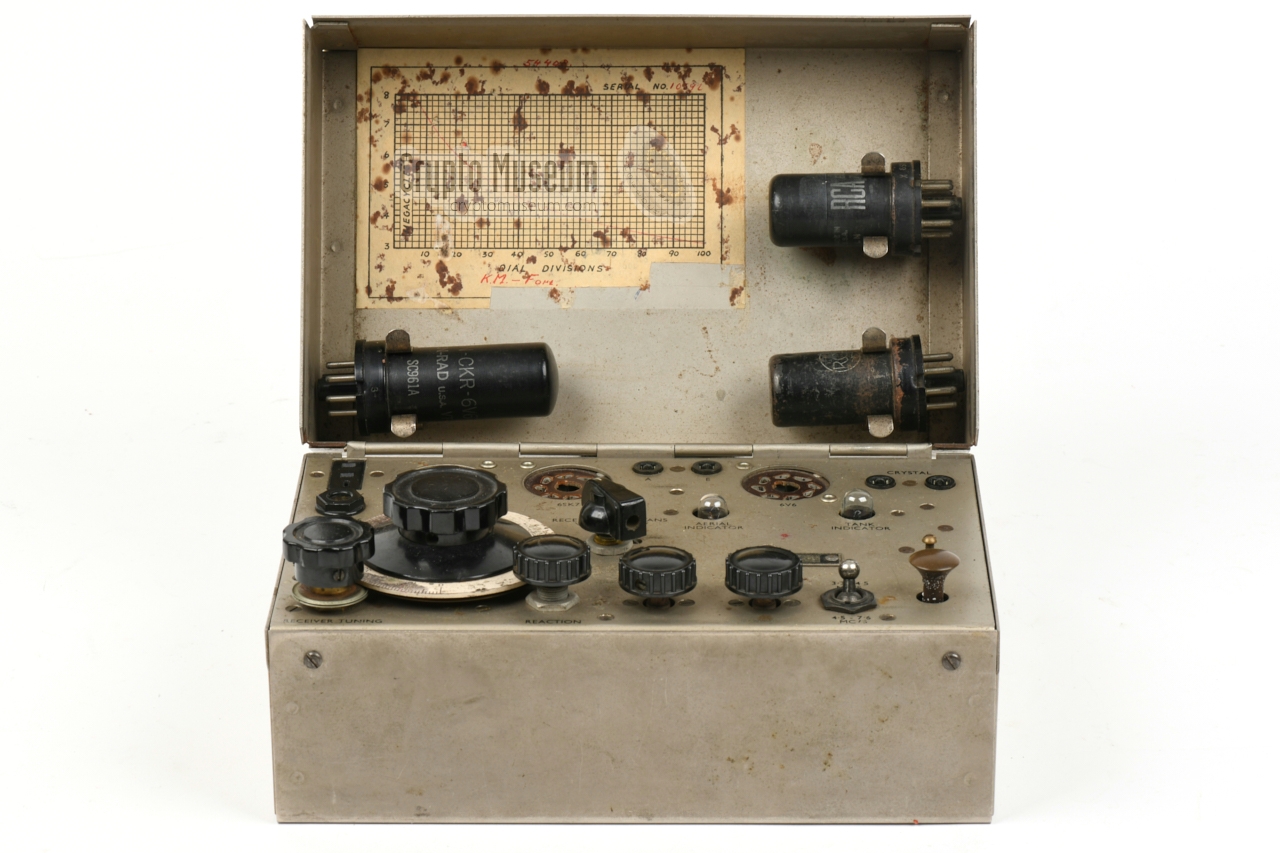
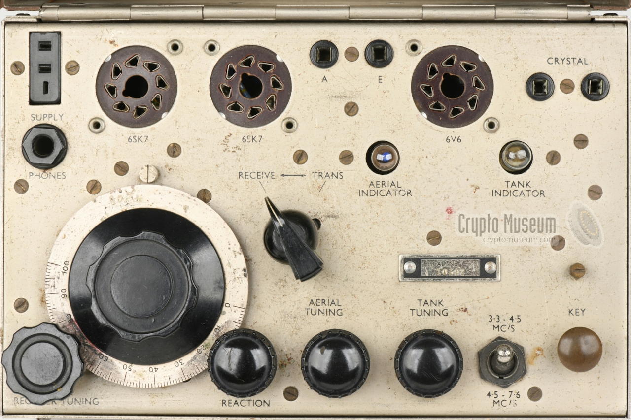
The diagram below provides a quick overview of the controls and connections
of the Paraset, all of which are located on the top panel. At the upper edge
of this panel are three 8-pin sockets in which the valves
should be installed. The valves have to be removed
– and stowed inside the top cover – before the
case can be closed. The PSU should be connected to the
socket at the top left.
The mode of operation (receive or transmit) is determined by the position of
the MODE-selector at the centre. The receiver can freely be tuned over the
entire 3-7.6 MHz range by means of the large and small knobs at the bottom
left, using the calibration chart
inside the case lid as a guide.
The frequency of the transmitter is determined by a quartz crystal
that should be
inserted into the socket at the top right.
After connecting a suitable wire antenna and counterpoise (ground),
the oscillator and antenna adjustments at the lower edge have to be tuned for
maximum output — whilst holding down the morse key —
using the tuning indicators (lamps) to find the optimum.
|
Mk VII In wooden enclosure Mk VII/2 In metal enclosure
|
- Small dimensions (probably the smallest transceiver at the time)
- Lightweight design (easy to transport and hide)
- Lightweight PSU
- Relatively high power output (5W)
- Valves accessible from the outside
- Easy to operate
- Service-friendly
|
- Valves have to be removed prior to closing the case
- No provision for external morse key
- No sidetone during transmission
- Potentially strong RF signal emitted from the receiver 1
- Under-dimensioned power supply unit
- 240V setting is actually the same as 225V setting
- Dangerous interconnection cable (the pins carry a high voltage) 2
|
-
When operated incorrectly.
-
This was corrected in later versions.
|
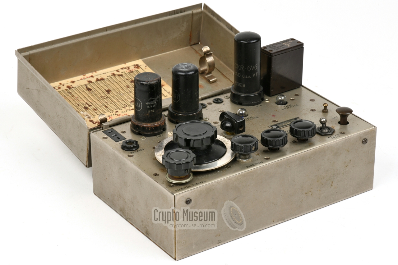
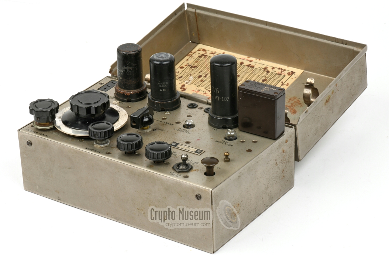
Like most Parasets, the one featured here is housed in a steel enclosure,
although some early ones were supplied in a wooden case.
It has a hinged cover
with clips to hold the valves when the device is in
transit, plus a calibration chart to convert the
linear receiver tuning scale to kHz.
Some Parasets were supplied in an unobtrusive travel suitcase
that also had space for the PSU, spare parts, wiring and
code material.
|
|
|
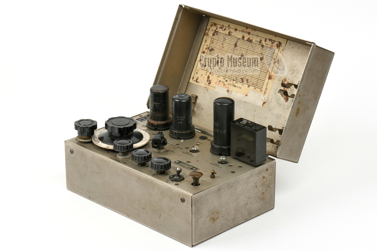
The actual transceiver is housed inside the metal (or wooden) enclosure
shown above, and is held in place by four screws (see below).
When the device is in transit, the three valves have to be removed and
should be stowed inside the cover, as shown in the image on the right.
➤ Look inside the transceiver
|
|
|
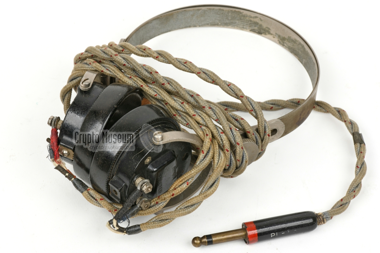
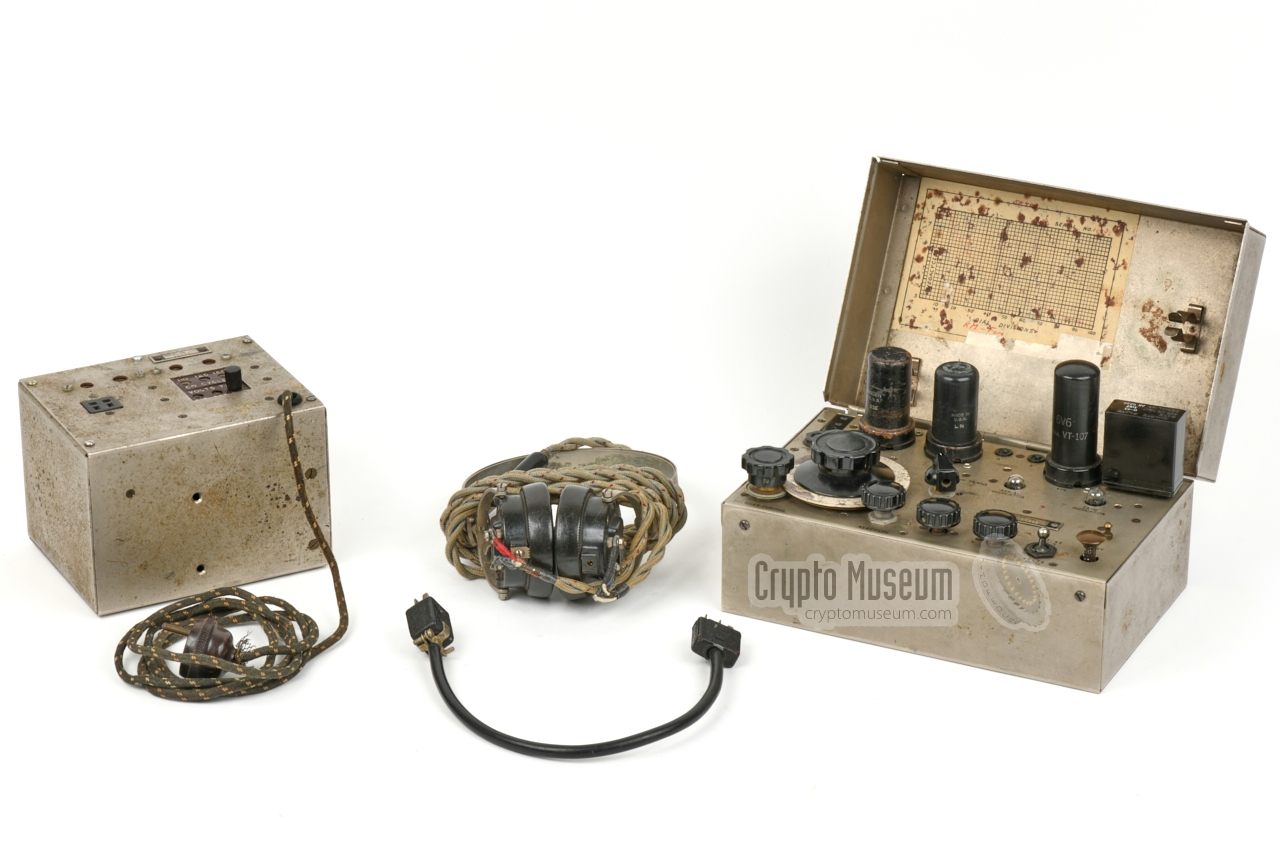
The Paraset contains an Audio Frequency (AF) amplifier that amplifies
the sound from the self-regenerative detector/receiver to a level that is
sufficient for high-impedance headphones.
The image on the right shows the original pair of 2000Ω headphones
that was supplied with the Paraset during WWII.
|
|
|
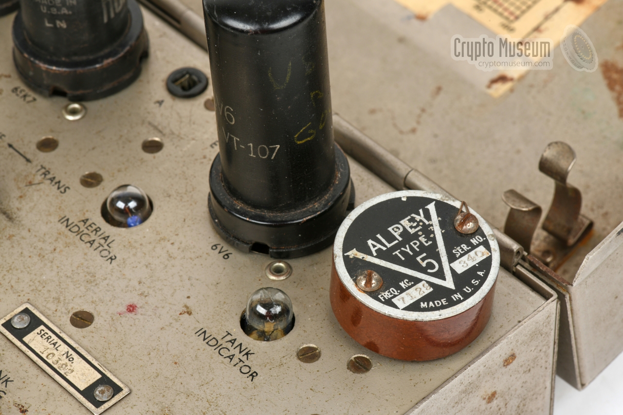
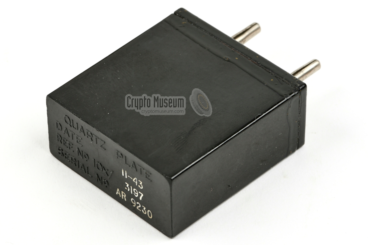
The transmitter is crystal-operated and requires a suitable quartz crystal
to be installed in the crystal socket
in the upper right corner.
The socket accepts virtually any USA/UK crystal with 3 mm pins that are
spaced 19 mm apart, such as the ones shown on the right.
Crystals with 4 mm pins, such as the
DC-34 and DC-35, will probably fit, but
are likely to damage the sockets (unless used with a 3 mm adapter).
➤ More about crystals
|
|
|
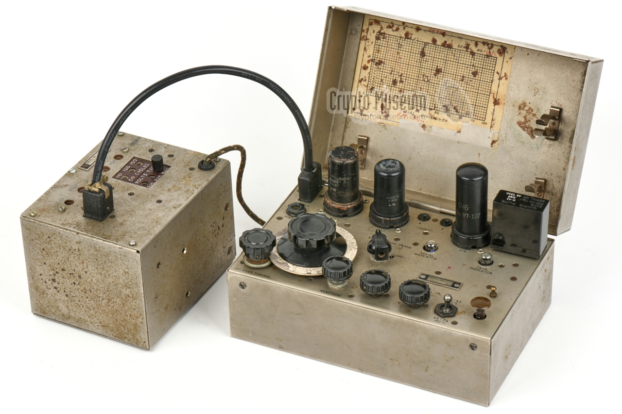
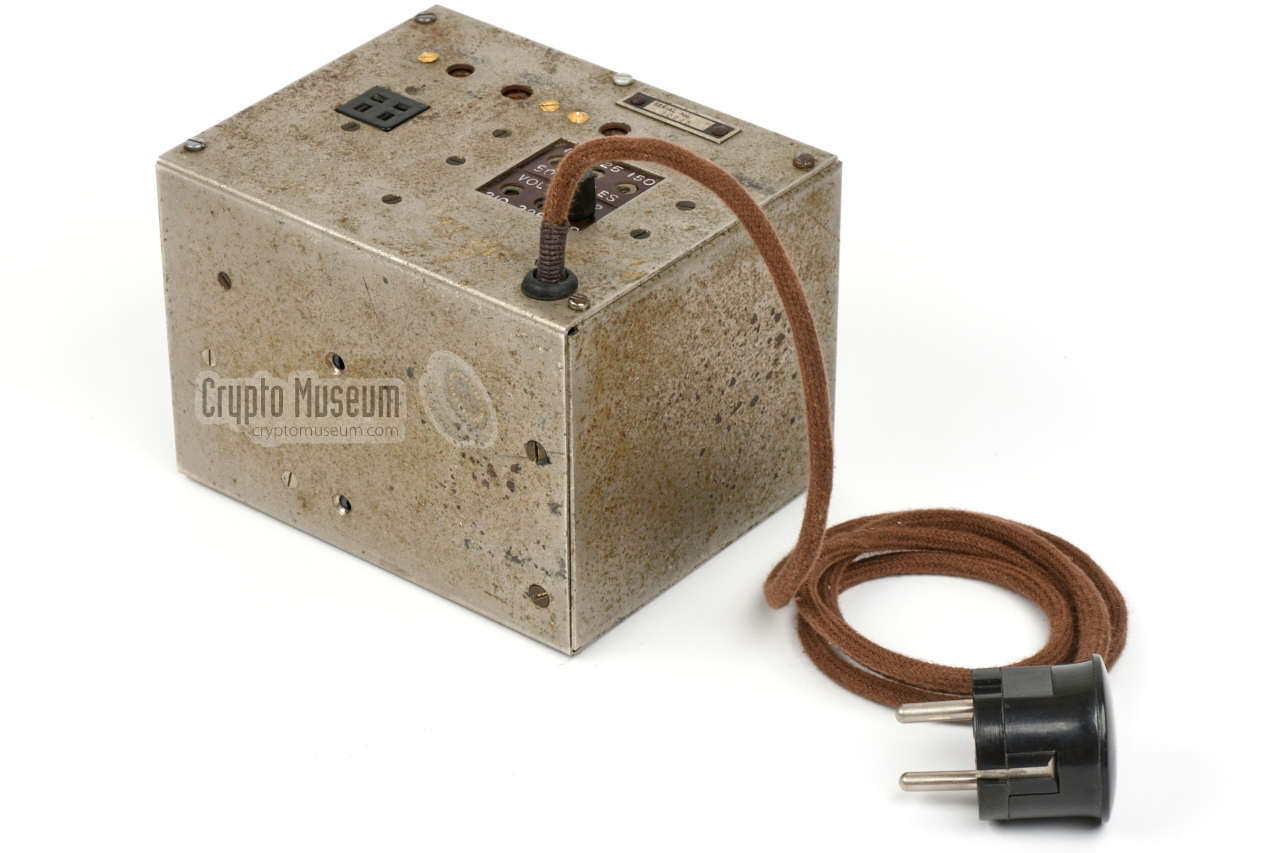
When the Paraset was to be used in an urban environment, it was usually
supplied with the mains power supply unit (PSU) shown in the image on the right.
At the front is a voltage selector that makes the PSU suitable for virtually
any AC mains network in the world.
The LT and HT voltages are available on the
4-pin Howard & Jones socket at the left.
A short cable is needed for connection to the Paraset.
➤ Connector pinout
|
|
|
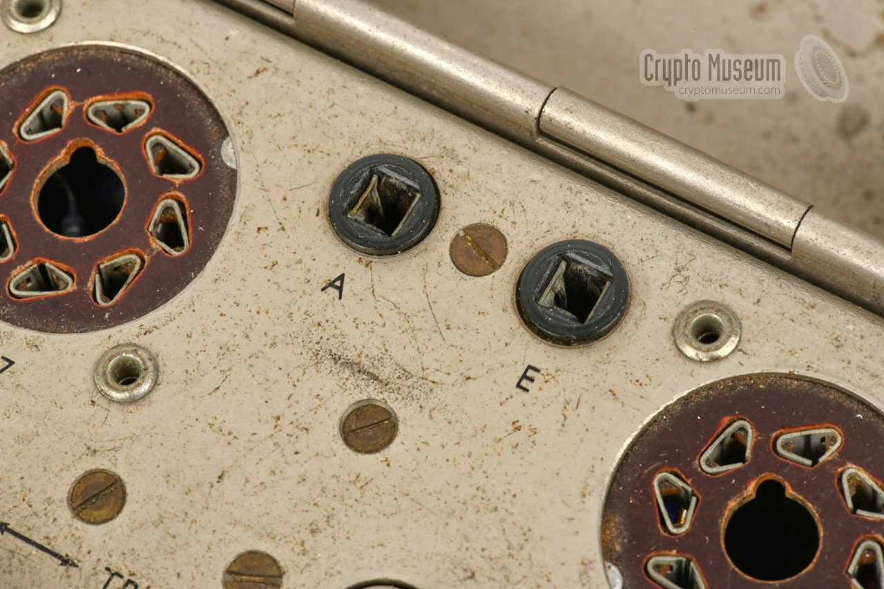
The tranceiver was operated with a long wire antenna which should be
connected to the terminal marked 'A' at the upper edge. As a general
rule: the longer the wire the better. In addition, a suitable
counterpoise wire should be connected to the 'E' terminal (earth or ground).
Suitable wires are shown in the image on the right. When possible, the
ground wire should be connected to the waterpipe or the central heating system
for improved performance.
|
|
|
There seems to be some confusion about the release date of the Mk VII,
especially among the various internet sources which often give 1941 as
the year of introduction. Most of these sources can be traced back to
Pierre Lorain's excellent book Secret Warfare [8], which was written
in 1972, at a time when there was very little information about these radio
sets in the public domain.
From later publications however, such as
Geoffrey Pidgeon's 2008 book The Secret Wireless War [10],
we now know that the the Mk VII was not introduced until late 1942.
For his book, Pidgeon – who worked at Section VIII of the SIS
at Whaddon from 1942 onwards –
interviewed many of his former colleagues, including Steve Dorman who
had joined Section VIII just after him. During the war, Dorman
secretly kept a diary which reveals that the Mk VII was still
in the development stage in September 1942. Pidgeon recalls that
it was released late in 1942, probably in November [9].
A good summary of the development of the early SIS radio sets,
is given by Dave Gordon-Smith in Electric Radio Magazine of September 2018 [9].
In his article The Agent Killer, he demystifies the history of the
clandestine SIS sets, based on information that has recently become available.
Another misunderstanding is that apart from the SIS, the Mk VII
was also used by the SOE. It was not. Although the SOE had used
SIS radio sets in the early years of the war, they established their
own research facility in 1942 at the Fryth (Station IX) near Welwyn
(Hertfordshire, UK). From then on they developed their own radio sets.
It is known that the SOE did test the Mk VII but found in inadequate
for SOE use [9].
The Mk VII was only used by the British
Secret Intelligence Service (SIS, MI6),
and by intelligence gathering agents of the resistance organisations in
occupied Europe.
|
Like its much larger and heavier predecessor, the
Mk V, it was usually dropped by parachute, which is
why both sets are known as Paraset or
Paracette, 1 although it is not entirely
certain whether this name applies to both devices or just to the
Mk V; the first set dropped in France.
The Mk VII was supplied directly by the SIS to intelligence gathering
resistance organisations in various occupied European countries,
such as France, The Netherlands and Belgium.
In the Netherlands, for example, it was
supplied to the Ordedienst (OD)
– the main resistance organisation – via the
so-called Swedish route.
They were delivered by the UK to Sweden, and then by boat to Delfzijl
in the north/east of the country, from where they were distributed.
|
|
|
|
The image above was taken by an unknown photographer between 1942
and 1945, and shows a Mark VII in use at an unknown address in or
near Amsterdam (Netherlands).
Below is a list of confirmed users 2 of the Mk VII, both during and after
WWII.
|
-
Derived from French, as the SIS initially intended the device
for use in France [6].
-
This list is by no means complete. If you know of any further users of the
Mk VII (Paraset), let us know.
|
Below is the circuit diagram of the Mk VII. At the left is the
transmitter, which is built around a metal 6V6 valve. At the bottom
left is the crystal. Note the twisted wire between the g1 and the anode,
which acts as a small capacitor (C3) that gets the oscillator going.
At the top left is the output transformer, that comprises a tank coil (L1a)
and an antenna coil (L1b). Each of these coils has its own pick-up loop that is
connected to a filament light bulb that acts as tuning indicator.
The receiver is at the right. It is built around two 6SK7 valves
and consists of a regenerative detector (V2) and an AF section (V3) that
amplifies the audio signal enough to drive a
pair of 2000Ω headphones. The frequency
is adjusted with C10, whilst R7 is used to find the optimum point of
regeneration. The MODE-switch (S1) selects between receiver and
transmitter. It switches the HT power (S1a) and the antenna (S1b).
In the middle position it is off. The circuit in the grey section at the top
right, derives the +245V voltage for the receiver from the +360V HT rail.
|
Below is the circuit diagram of the original
mains power supply unit (PSU).
It consists of a large transformer with a selection of taps on the primary
side, that makes the device compatible with virtually any AC mains network
in the world. The double capacitor (C2, C3) acts as a mains filter.
At the secondary side is a double HT winding and a separate
6V winding for the filaments of the valves. The HT voltage is rectified in
a 6X5 rectifier valve (V1) and smoothened by capacitor C1.
The output is available on a 4-pin Jones socket, whilst the
Mk VII itself has a 3-pin Jones socket. A short
interconnection cable is needed to connect the two devices together.
In the initial version, the interconnection cable has plugs at both ends,
which makes it dangerous and potentially lethal. In later versions this was
solved by swapping the 3-pin plug for a 3-pin socket [6].
|
|
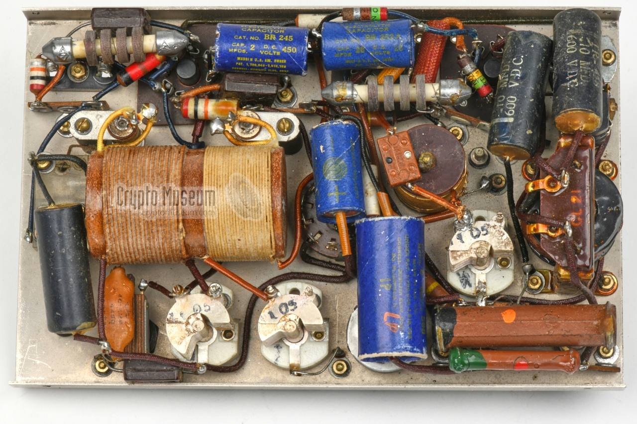
The Mk VII is housed in a steel rectangular container that measures
222 x 142 x 110 mm and weighs 2580 grams; valves and one crystal included.
All parts are mounted to the reverse side of the control panel, which is
bolted to the metal enclosure by means of four screws at the edges.
|
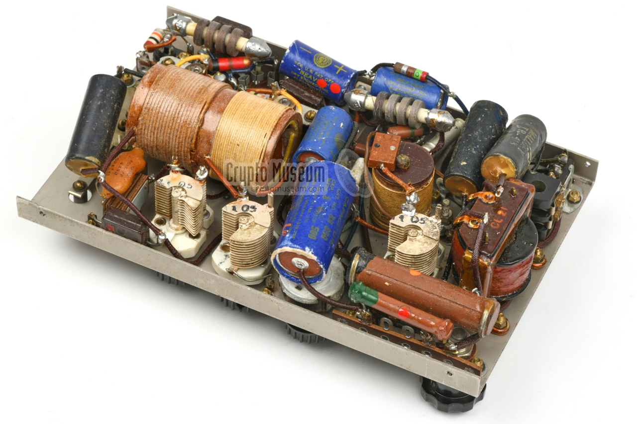
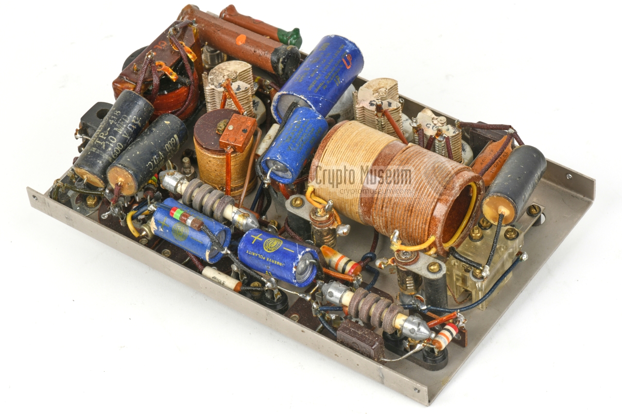
After removing the four screws, the
interior can be lifted from the enclosure,
as shown in the image on the right. All components are soldered directly to
the bottom of the valve sockets and the connectors, or to mounting stubs or
special solder strips that are bolted to the front panel.
The large coil at the centre
is the combined oscillator/antenna coil – in
fact a transformer – which is wound onto a large paxolin cylinder.
Inside the cylinder are the pickup coils
for the two tuning indicators; one at each end.
Their filament light bulbs protrude the control panel.
|
|
|
|
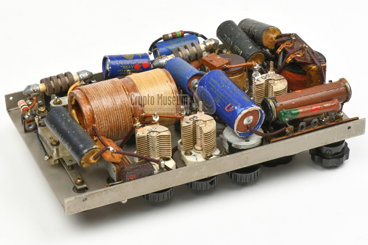
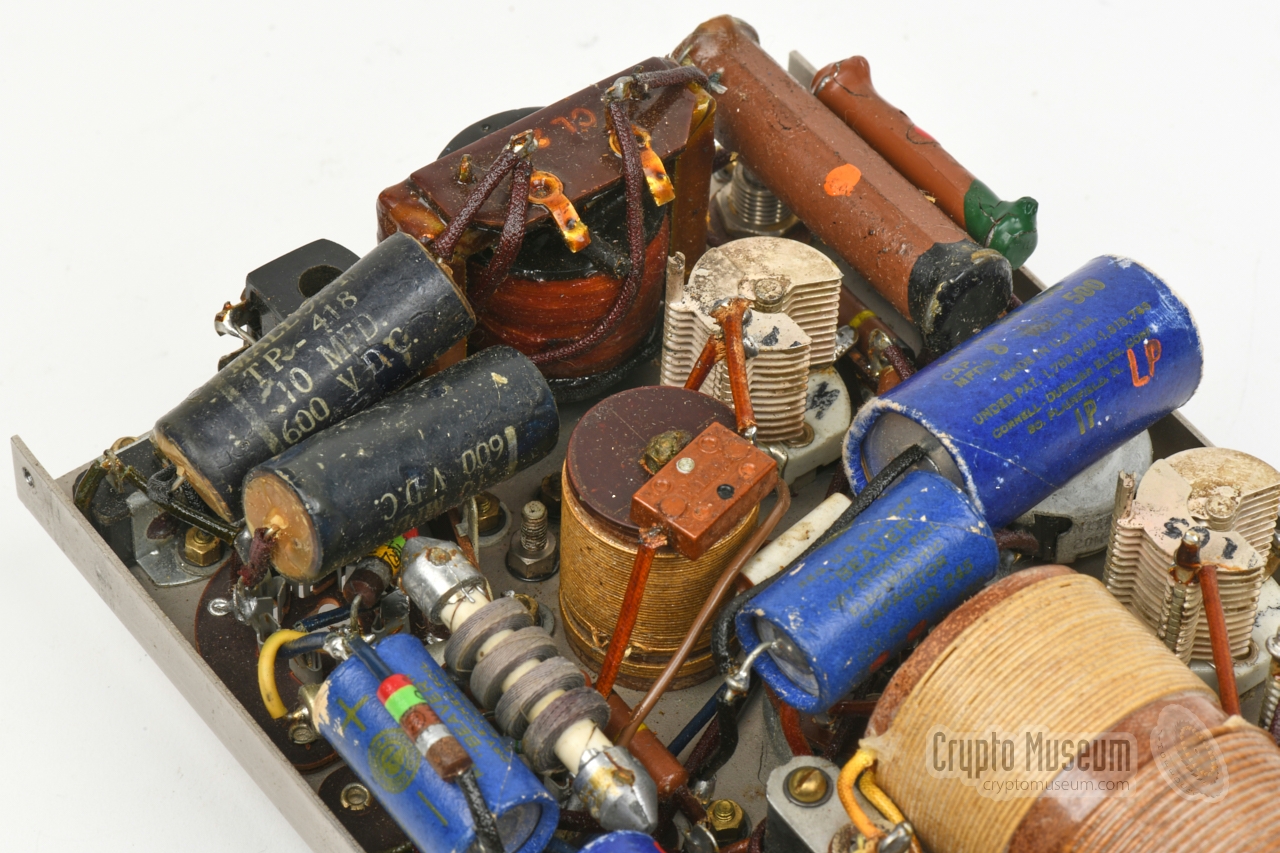
Despite its age and the stress under which it was developed, the Mk VII is
a service-friendly device. It is mechanically well constructed and all
components are easily accessible. Considering the fact that the device shown
here is 80+ years old (in 2021), it appears to be well preserved.
|
The fact that the valves are fitted at the front panel rather than inside the
enclosure, can be seen as a disadvantage (they must be removed to close the
case) but also as a feature, as they can be replaced without
dismantling the Mk VII.
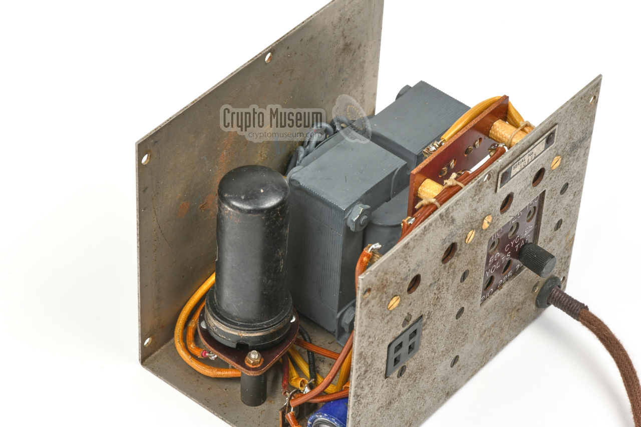
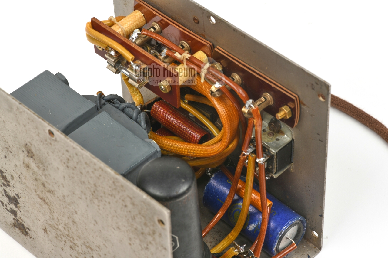
The power supply unit (PSU) is housed in a metal enclosure that consists of
a U-shaped base — to which all parts are mounted — and a U-shaped cover. The
cover has ventilation slots at the top and is held in place by 5 screws at the
front and 5 at the rear. After removing all 10 screws, the cover can be lifted
and the interior is exposed.
|
|
|
WARNING —
Note that the interconnection cable of the initial Mk VII can be dangerous,
as it has plugs (with pins sticking out) at both ends. When the cable
is plugged into a live PSU, the pins at the other end carry the potentially
lethal voltage of +360V. Always install both ends of the cable - before -
plugging the PSU into the mains. The gender of the plug and socket
at the transceiver end was swapped on later models [6].
|
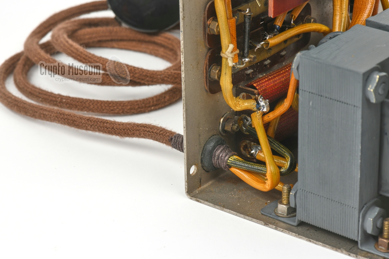
When we received our Mk VII in September 2020, it was in an unknown state,
but we knew that the power supply unit (PSU) was broken. A first
investigation revealed that the rubber of the original mains cable
had become brittle
as a result of which the two mains wires were shorted.
|
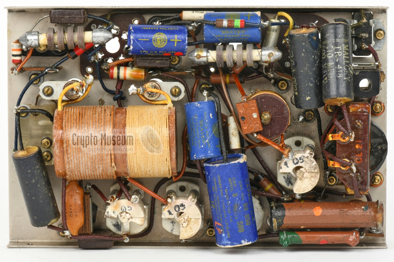
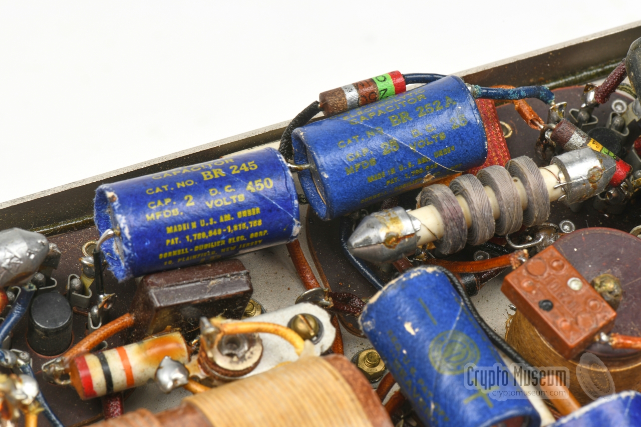
We noticed that the two
mains filter capacitors had exploded and that
one of the secondary HT windings had a short circuit. This means that the
mains transformer was lost.
In addition, the
smoothing capacitor and the bleeding resistor
had both died as well, which means that not a single component
inside the PSU had survived.
To make matters worse, a previous owner had drilled four holes in the front
panel, to make the various voltages available on banana sockets.
Surprisingly, the device does not have a mains fuse, so it may easily
have been overloaded.
|
|
|
|
Although it is possible to have the transformer rewired, we decided to
replace it with a same-size modern alternative for safety reasons.
We also knew that the original transformer was under-dimensioned,
as wartime users frequently complained that it was always running hot,
and that in several cases they had to interrupt the transmission in
order to give it a chance to cool down.
|
After replacing the passive components, the new transformer was fitted
in the existing mounting holes and was wired to the rectifier socket,
the output connector and the voltage selector. In addition, a new
6X5 rectifier valve was installed.
It was decided to leave the non-original banana sockets in place, as otherwise
it would be very difficult to cover the four holes in the front panel. Although
these banana sockets were not present when the device was released, they are
left as a witness of an aftermarket modification.
The result is visible in the image on the right.
|
|
|
Although there is no fuse in the original design, it was decided to fit an
era-correct one inside the device – in series with the primary winding of
the transformer – for safety reasons and to protect the transformer should the
6X5 valve short out unexpectedly. As the four banana sockets would otherwise not
have a function, they were wired in parallel with the 4-pin Jones socket,
as was the case in the 'original' aftermarket modification.
The result is shown in the circuit diagram below:
|
| |
Restored power supply unit
|
|
|
The Mk VII itself was first tested with two professional adjustable
power supply units: one set to 6.3V for the filaments, and one gradually
raised from 90V to 340V for the anodes of the valves.
Whilst doing this, we used an infrared camera to check if any parts
were internally overheating.
|
Once we were satisfied that this was not the case and that there
were no short circuits, it was time to conduct a first test.
Wires were connected to the
antenna and ground terminals,
a 3.518 MHz crystal was installed, the MODE-selector was set to TRANS,
and the morse key was held down.
After a bit of playing with the TANK and AREAL tuning controls, the
two indicator lamps lit up and the transmitter came to life. It
produced a strong and clear signal on the desired frequency.
It appeared to be easy to find the optimum setting,
which is just below maximum light.
|
|
|
|
Next, the headphones were installed and the MODE-selector was set
to RECEIVE, but no sound was heared. After wiggling the valves,
it became clear that the socket of V3 was worn out. The contacts
were fixed and noise was heared through the headphones, but no signal
was received.
|
Furthermore, the reaction potentiometer (R7) was stuck, as a result of
which the reaction point could not be adjusted. After oiling its axle,
the resistors and capacitors of the receiver circuit
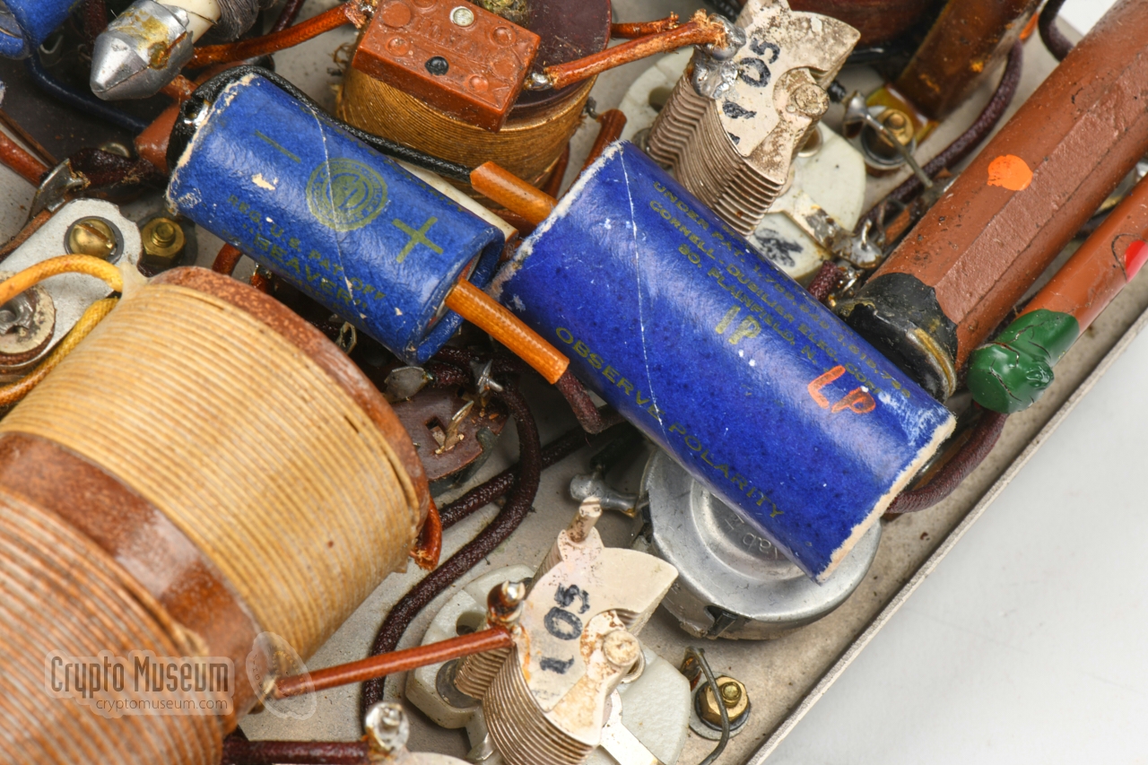
were checked. It appeared that two resistors (R4, R9)
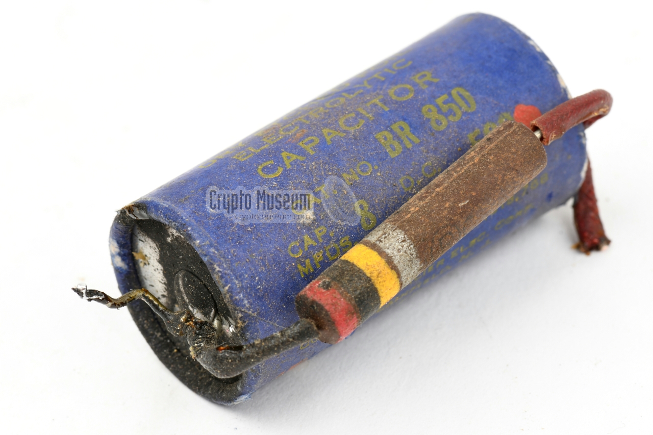
were way out of spec, and that all electrolytic capacitors (C13, C16,
C18 and C19) were gone.
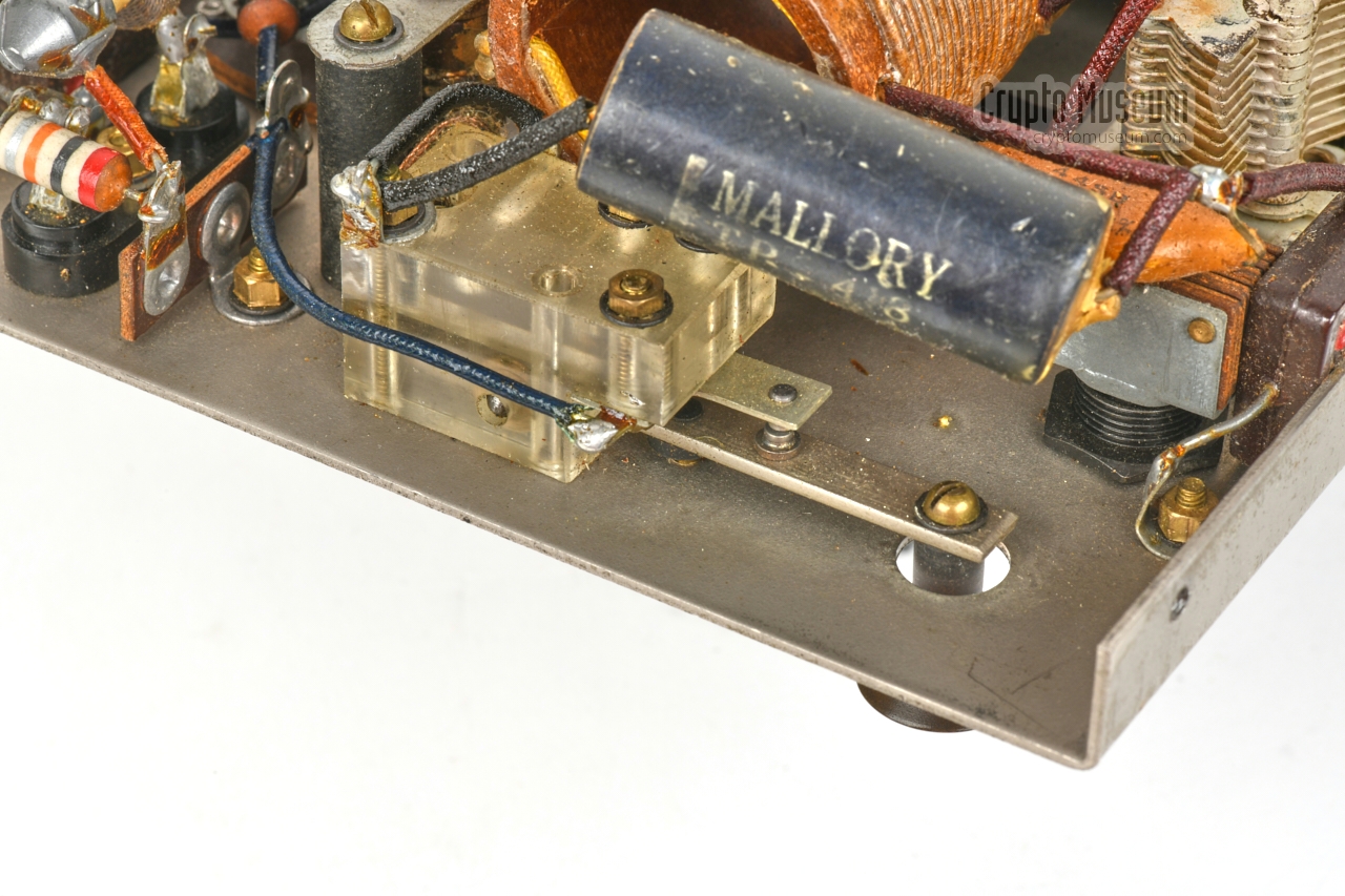
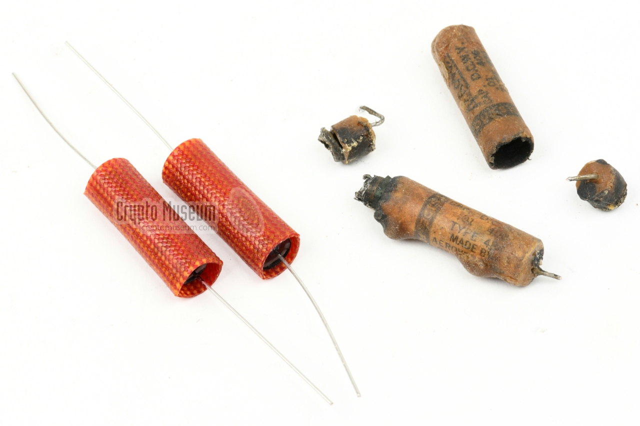
The resistors were replaced by modern ceramic alternatives, covered
in old sleeves, whilst the electrolytic capacitors – with their prominent
blue jackets – were carefully disassembled and emptied, so they could
house a replacement.
|
|
|
|
Whilst carrying out the repairs, it was noticed that the coupling
capacitor (C14) between V2 and V3 had been replaced in the past.
As it looked way too new, it was replaced by a new part that was
made to look old. It was also noticed that there were some solder
problems on the taps of the receiver coil (L3). Apparantly, the
wire to the cathode of V2 had been broken in the past.
|
This was probably caused by frequent wiggling when installing
the valve (V2).
As the wire had been replaced by a modern one, and the solder joints on
the receiver coil (L3) looked messy, we decided to replace it with a
properly sleeved one, and rework the solder joints of the receiver coil.
After carefully checking the restored parts, the receiver was powered
up again and a 3.4 MHz signal was applied to the AERIAL input.
After turning both tuning knobs, and adjusting the REACTION control knob
as per instructions in the manual,
the signal came through loud and clear.
|
|
|
|
Surprisingly, the
index on the linear tuning scale still
corresponds exactly with the
graph inside the case lid —
80 years after the device was manufactured and calibrated.
The restored Parsaset was then closed, and its operation was checked
in combination with the original PSU, of which the restoration
had meanwhile also been completed. It appears that transmitter
and receiver are very stable and easy to operate.
No wonder that the Paraset
has become such a popular repro subject.
|
Short circuit in brittle mains cable (PSU) One of the secondary HT windings of the mains transformer shorted out (PSU) Both mains filter capacitors blown (PSU) Smoothing capacitor gone (PSU) Bleeder resistor has become infinite (PSU) Rectifier valve (6X5) missing (PSU) - Four extra holes in front panel (PSU)
Interconnection cable stiff and too modern 1 Both Howard & Jones plugs unstable Reaction potentiometer stuck Receiver very insensitive
|
-
The original braided cable had been replaced by a modern rubber cable
by a previous owner.
|
- Mains cable replaced with (secure) 3-wire brown braided cable
- Mains ground connected to chassis (for safety)
- Both mains filter capacitors (V2, C3) replaced
- Smoothing capacitor (C1) replaced (inside original casing)
- 200k bleader resistor (R1) replaced
- Transformer (TR1) replaced
- Era-correct fuse holder added
- 6X5 rectifier valve (V1) replaced
- Banana sockets rewired with era-correct wiring
|
- Interconnection cable replaced by 3-wire brown braided cable
- Both Jones connectors restored
- Valve socket (V3) repaired
- Reaction potentiometer (R7) repaired
- Wire between L3 and the cathode of V2 replaced
- C13 (2µF) replaced (inside original casing)
- C18 (8µF) and C19 (2µF) replaced (inside original casing)
- R9 (75k) replaced
- R4 (1M) replaced
|
WARNING —
Be careful when trying to use an original Mk VII power supply unit,
as a lot is wrong with its design. First of all, there is no power switch
and no fuse whatsoever. This means that the transformer is activated and
the valve filaments are heated as soon as the device is plugged into the mains.
Furthermore, the
transformer is under-dimensioned, as a result of which it can overheat
when the transmitter is used for an extended period of time.
After 80+ years, all of the electronic parts are most definitely gone,
and the (rubber) wiring is likely to have become brittle over the years.
In addition, the 6X5 rectifier tube is notorious for shorting out to ground
– especially when driven at its limits –
as a result of which it might blow one of the HT windings (as was the case
in our device). The latter can be overcome by using a separate 6V winding
for the filament of the 6X5 [8], but this was not avaiable on the original
transformer.
Also note that the 240V setting of the voltage selector, connects to the
same tap on the transformer as the 225V setting. This is particularly
important, as the mains voltage in continental Europe has been raised
at the beginning of the century from
220V to 230V, and is in many cases even higher that that.
Mains voltages of 240V are no exception. As a result, the transformer
may saturate and eventually overheat and break down.
Device Clandestine radio transceiver Purpose Agent communication Designator Mk. VII Year Late 1942 Country UK Users SIS (MI6), European resistance Design SIS (MI6) Section VIII (Whaddon Hall) Manufacturer SIS (MI6) Section VIII (Whaddon Hall) LT 6.3V, 950mA Dimensions 222 x 142 x 110 mm Weight 2580 g 1
|
-
Including all three valves and one crystal.
|
Modulation AM R/T, CW Frequency 3 - 7.6 MHz Circuits Regenerative detector, AF stage Valves 6SK7 (2x) Output High impedance headphones Antenna Long wire (and ground wire) HT +245V DC (derived from +360V), 10mA
|
Modulation CW Frequency 3.3 - 7.6 MHz Ranges (1) 3.3 - 4.5 MHz, (2) 4.5 - 7.6 MHz Output 4 - 5 W Circuit Oscillator/PA Valve 6V6 Morse key Internal only HT 360V, 40-50mA
|
Input 110 - 240V AC (6 steps), 40 - 60Hz Current LT: 950mA, HT: 10mA (RX), 40-50mA (TX) Valve 6X5 (rectifier) Dimensions 114 x 110 x 110 mm Weight 2700 g
|
|
Below is the pinout of the Howard & Jones 3-pin socket at the front panel
of the Mk VII, when looking into the socket. Note that on later versions
of the Mk VII, the female chassis part was swapped for a male chassis part,
for safety reasons. The pinout was kept the same though, and uses the same
pin numbering. Equivalent cable parts are also available from Hirose (HRS).
|
- HT +360V
- Ground (common)
- LT ~6.3V
|
|
|
The LT and HT voltages ae available on a Howard & Jones 4-pin female
socket at the front panel of the PSU. Below is the pinout when looking into
the socket. A short braided interconnection cable was used to connect the
Mk VII to the PSU.
|
- HT +360V
- not connected
- LT ~6.3V
- Ground (common)
|
|
The 6V6 is a beam-tetrode in a metal enclosure, developed in the mid-1930s
by RCA for use in the audio stages of broadcast receivers.
They are frequently found in single-ended or push-pull amplifiers,
and even in today's vintage/retro valve-based amplifiers. Apart from the
use in audio amplifiers, the 6V6 can also be found in the oscillator and
PA stages of short-wave transmitters.
In the Mk VII, the 6V6 is used in the single-valve transmitter,
as a combined oscillator/power amplifier (PA). In this configuration it produces a maximum power output
of 5 Watts.
➤ 6V6 datasheet
|
The 6SK7 is a remote-cutoff pentode in a metal enclosure,
developed for use as high-gain
radio frequency (RF) and intermediate frequency (IF) amplifiers in radio
receivers. Because of its cutoff characteristic, it can handle high
signal levels without cross modulation or distortion. It is also suitable for
receivers with automatic gain control (AGC).
In the Mk VII, the 6SK7 is used in both stages of the receiver:
the regenerative detector (V2) and the audio frequency (AF) amplifier (V3).
➤ 6SK7 datasheet
|
6X5 is a full wave rectifier. It contains two diodes with a common – indirectly
heated – cathode. The valve is notorious for shorting out to ground and
destroying one of the windings of the transformer to which it is connected,
especially when driven to its limits. This can be avoided by using a separate
(floating) 6V supply for the filament of the 6X5 or by adding a fuse.
➤ 6X5 datasheet
|
- Cor Moerman, Mk. VII (Paraset) - THANKS !
Received September 2020.
- Louis Meulstee, Wireless for the Warrior, volume 4
ISBN 0952063-36-0, September 2004.
- Wikipedia, Paraset
Retrieved May 2021.
- Henk van Zwam, The Whaddon Mk-VII, a.k.a. 'The Paraset'
Visited 6 May 2021.
- Johnny Apell, The Whaddon Mk VII - Paraset Clandestine Radio
SM7UCZ. Visited 6 May 2021.
- David White, Personal correspondence
August 2009, May 2021.
- Larry, The notorious 6X5 and kin
Aniques Radio Forum. Retrieved May 2021.
- Pierre Lorain, Secret Warfare
ISBN 0-85613-586-0. 1972. pp. 43-46.
- Dave Gordon-Smith (G3UUR), The Agent Killer, A Spy Set with a Bit of a Reputation
Electric Radio Magazine #352, September 2018. pp. 2-15.
Reproduced with kind permission of Electric Radio Magazine.
- Geoffrey Pidgeon, The Secret Wireless War
ISBN 978-09560515-2-3. August 2008.[Heading]
- Photograph of clandestine transmitter in Amsterdam during WWII
Collectie Stadsarchief Amstrerdam 10003/14615. OSIM00007003791.Unknown author.
|
|
|
|
Any links shown in red are currently unavailable.
If you like the information on this website, why not make a donation?
© Crypto Museum. Created: Friday 14 May 2021. Last changed: Wednesday, 05 November 2025 - 12:08 CET.
|
|

|
|
|


![Clandestine Mark VII transmitter in use in Amsterdam during WWII, probably by the Ordedienst (OD). Collectie Stadsarchief Amstrerdam [11].](img/OSIM00007003791_large.jpg)