|
|
|
|
|

|
|
SBO Germany Telefunken FS-5000
Digital Storage Unit
The FS-5000 is controlled by a small digital unit,
called the Digital Storage Unit (DSU), that is attached to the other
modules at the front right.
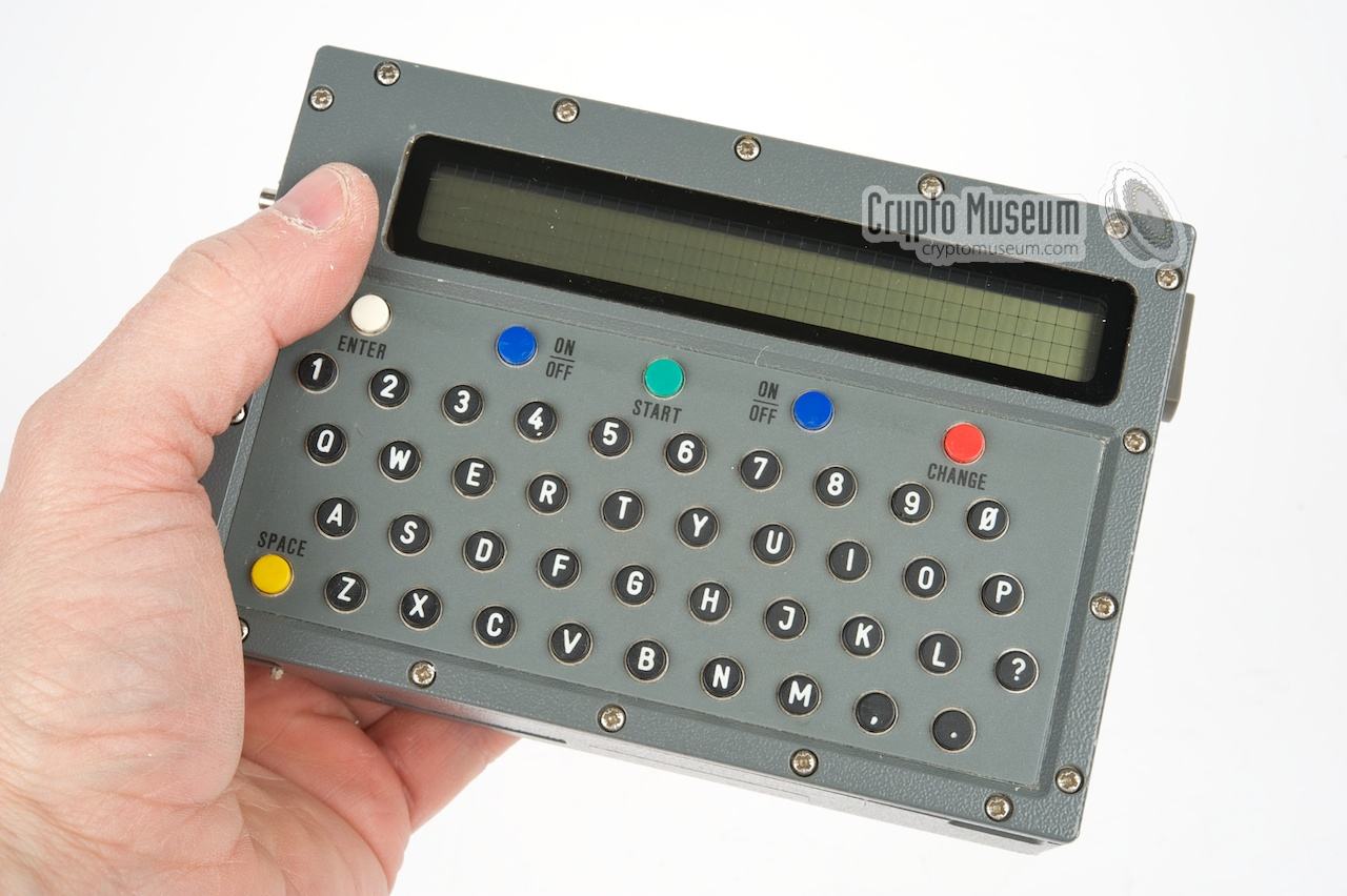
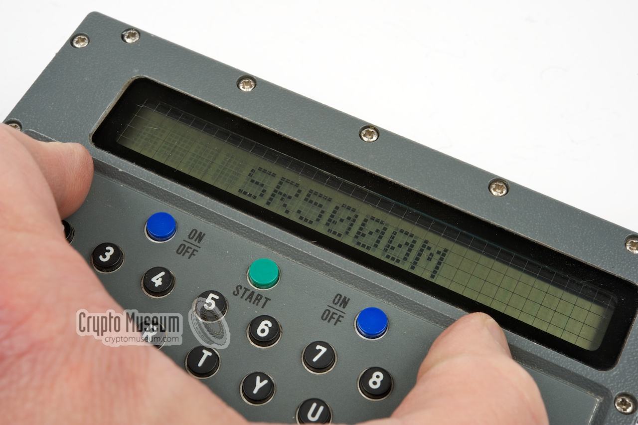
It has a 45-button keyboard and a 16-character LCD screen for communication with the user, and has a built-in high-end cryptographic engine.
The DSU can be used as part of the FS-5000 radio station but also stand-alone
using batteries.
|
The DSU is used for entering and encrypting messages, reading messages
and setting the RX and TX frequencies. Settings and messages are retained
in memory by a set of backup batteries.
The image on the right shows a typical DSU as it was used in Germany.
The keyboard consists of 45 hard-plastic keys with the full alphabet (A-Z),
numbers (0-9), full-stop and comma. The space charcter is at the bottom left
and has a yellow key. At the top row are 5 coloured keys. The two blue ones
are used as ON/OFF button. White is used for ENTER (YES) and Red is CHANGE
(NO).
|
|
|
The keyboard is somewhat recessed, so that the keys can not be activated
accidently when the toolbox is mounted over the DSU.
At the top is a 16-character LCD screen which is used for communication with
the user. The firmware is adapted for each country, so that the majority
of messages is in the native language. The keyboard however, always has
the QWERTY-layout.
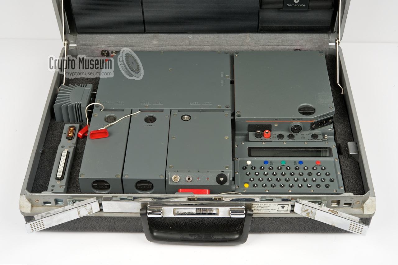
The DSU is connected to the other modules via the receiver. The 25-way
D-type connector at the bottom of the DSU mates with the socket on the right
side of the receiver. The two guide-pins on the side of the DSU allow the unit
to be locked securely by a lever on the receiver's side.
This is the default position
of the DSU, but it was also possible to use an extension cable.
|
|
The DSU can be used in stand-alone mode (i.e. separated from the FS-5000)
in which case it is powered by the internal backup batteries. This is the
main reason for the relatively high voltage (7V) of the internal batteries.
For proper operation, the DSU needs a fresh pair of batteries.
|
Stand-alone mode allows the user to prepare a message off-line
whilst being away from the transmitter. One or more messages can be
entered and encrypted, and the transmission frequency can be programmed
in advance.
Stay-behind personnel could also program the internal Real Time Clock (RTC)
for scheduled (unmanned) transmission of the messages.
The image on the right show the DSU performing its self-test in
stand-alone mode.
In this case it is powered by two fresh Tadiran 3.6V Li-cells.
|
|
|
When the device is turned off, the device enters SLEEP-mode and
the messages and any other settings are retained by the backup batteries.
In SLEEP-mode the device consumes less than 0.19mA, which means that data
will be retained for years if necessary. As soon as the RTC reaches the
preset time and date, it will turn on the DSU (and hence the complete
FS-5000 station), transmit its message(s) and turn itself OFF again.
In the same way it was possible to receive message at a pre-determined time
and date, whilst being away from the radio station.
|
|
At the right side of the DSU is a small circular lid that gives access to
a cylindrical battery compartment that takes two 3.5V lithium cells.
The cells have the shape of standard penlight batteries but produce
a total of 7V that is needed to retain the settings and message(s).
|
It is also possible to use the DSU stand-alone (i.e. not connected to
any of the other modules), in which case it is powered by the internal
batteries. This is the reason that the batteries produce 7V. In order
to save the batteries, the DSU will enter SLEEP-mode when it is not used.
The batteries are also used to keep the Real Time Clock (RTC) on the
crypto board running (see below). As the RTC draws only 10µA
in standby, the batteries can keep the clock running for many years.
A spare set of 3.5V SAFT batteries was supplied with the toolkit.
|
|
|
Please note that the batteries are not needed to operate the radio station
and the DSU. If there are no batteries present inside the DSU, the only
problem is that the settings (frequency) and the current messages in the
internal memory of the DSU are lost when the device is switched OFF.
|
Also note that, as the batteries get older,
their internal resistance (Ri) will rise. As a result they may seem
good when measured with a volt-meter, but they do not deliver enough energy
to power the DSU when used off-line.
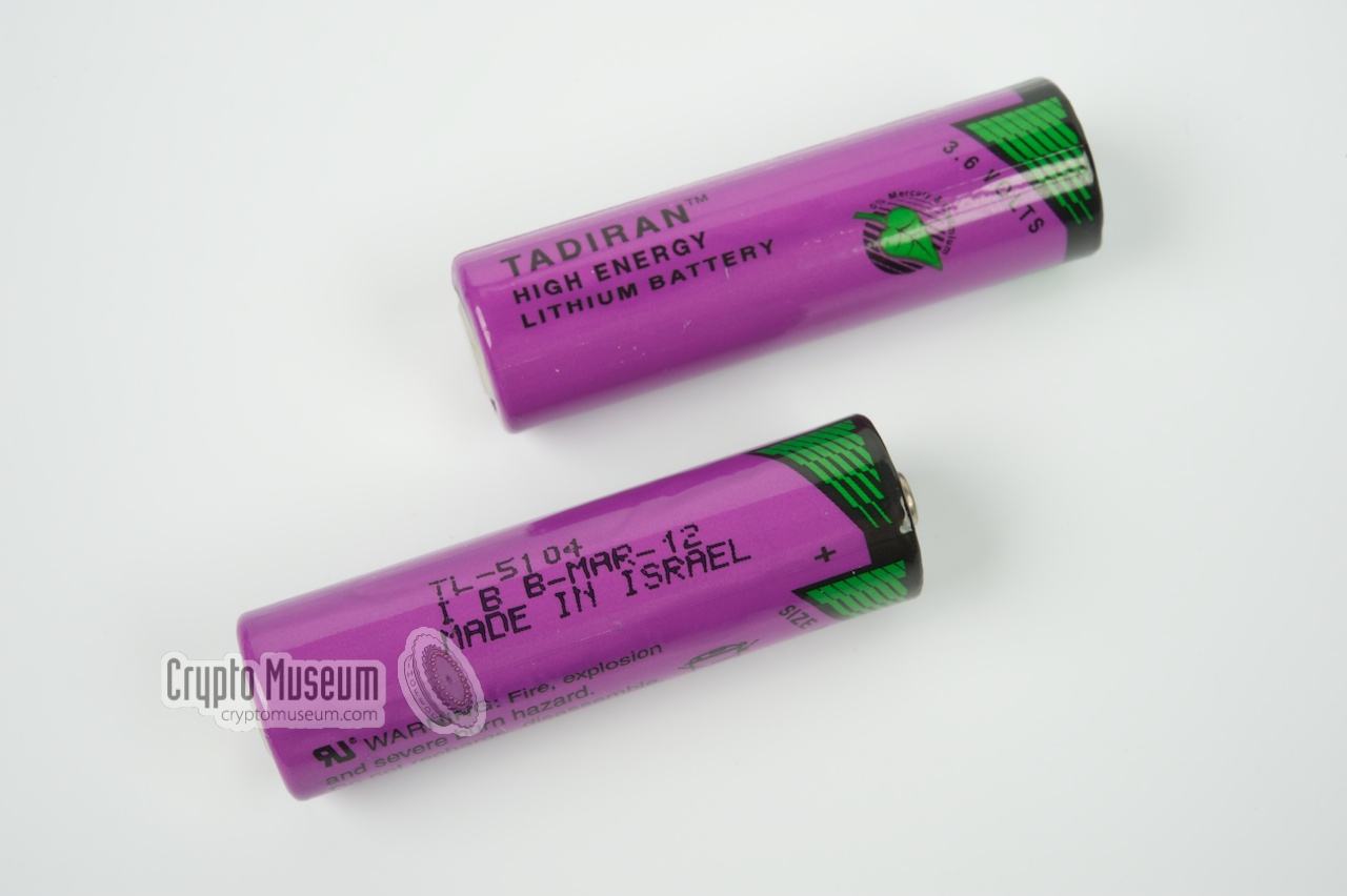
Replacement batteries for the DSU may be difficult to find.
A good modern alternative for the 3.5V SAFT batteries that were originally
supplied with the FS-5000, is the 3.6V TL-5104 Li-battery made by
Tadiran (Israel). They have the same size as the original and produce
7.2V. They allow stand-alone use of the DSU.
|
|
|
Another good alternative is available from EVE™ (Energy Very Endure).
It is also a 3.6V Lithium-battery at AA-size with a capacity of 2600mAh
and is available from component supplier Conrad Elektronik in Germany
for approx. EUR 4.99 (order number 650773-89). Also available from Conrad
is a 3.6V/2400mAh Li-battery from Emmerich™ for EUR 4.69 (order
number 651244-89). Many thanks to Günter König in Germany for this information.
|
Another solution that allows the DSU to be powered by an external 7V DC source
is the special adapter shown in the image on the right. It is plastic rod
that replaces the two 3.5V batteries. At the right is the top contact (+)
whilst the negative side (-) is connected to the cap at the left. Two wires
(red/black) with banana-type plugs at the end allow the adapter to be
connected to an external source.
The adapter was only supplied to stay-behind personnel. It allowed them to
operate the DSU off-line in case the batteries were dead or low.
|
|
|
Many thanks to Jim Meyer [6] for supplying the image above. Jim apologizes
for the rather low quality of the image. Perhaps it would be a good idea if
someone would make a small quantity of these adapters (anyone?).
|
|
In normal operation, the DSU is located
to the right of the receiver,
so that the connectors of the two devices mate. This is how the FS-5000
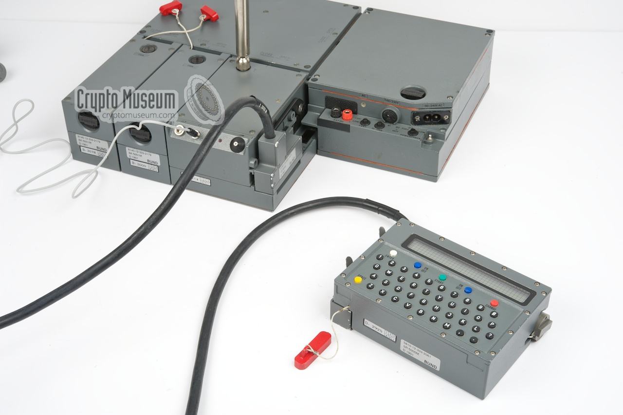
was designed in 1985. A later extension cable,
called VK-5000, allows the DSU to be used as a console.
This cable was probably introduced in 1992.
|
The cable is approx. 1.5 meters long and has purpose-built connectors at
both sides. The side that connects to the receiver
is marked VK-5000 and is locked in place
in the same manner as the DSU by pushing the handle all the way down.
The other side of the cable is connected to
the 25-way socket on the DSU
and is held in place by two ingenious clips.
The extension cable was probably used for a more convenient operation
and for use in the field by Special Forces.
The image on the right shows the DSU connected to the receiver via the
VK-5000 extension cable.
|
|
|
Interestingly, the cable carries the later TST-logo rather than the original
Telefunken logo (or no logo at all). TST (Telefunken Systemtechnik) was
established in 1989 as the merger of two former AEG divisions within
Deutsche Aerospace (now EADS). According to the manufacturing codes on the
connectors, the extension cable was made in 1992 or later.
|
When you are uncertain about a correct operation of the FS-5000,
it is possible to test the interface of the DSU, using the small
test device, or X-Unit, that is part of
the toolkit.
This test requires the DSU to be used in stand-alone mode,
which means that it needs to have a fresh pair of internal batteries
installed.
➤ More information
|
|
|
|
|
Reading the version number
|
|
|
|
In order to read the version number and date of the firmware, press and
hold the white and red keys (ENTER/CHANGE) immediately after switching the unit
on. After completing the self-test, the information will be displayed.
It consists of the name, version number, date and manufacturer.
|
The various bits of information are divided over several lines. Each
line stays on screen for 1 sec. The Special Forces
version of the DSU (SR5000M) shows for example this information:
SR5000M
Version: 10.01
Vom: 12.08.1993
ANT-BACKNANG
At the time, ANT Nachrichtentechnik GmbH
was a joint venture between AEG Telefunken, Bosch and others,
based in Backnang (Germany).
|
|
|
The version number of the firmware of the SR5000M is 10.01 and the
release date is 12 August 1993. The date codes on the electronic
components and the batteries however, indicate that the units were
built around 1988.
This suggests that the FS-5000M
(i.e. the German Special Forces version) is in fact the original
Stay-Behind version with modified software. As the stay-behind
organisations in most countries – including Germany – were dismantled
in 1992, it is quite possible that the radio sets were given a new
lease of life at the Bundeswehr (German Army).
Apparently, the firmware was written (or at least modified) by
ANT Nachrichtentechnik in Backnang (Germany).
Before 1983, 51% of ANT
was owned by AEG Telefunken.
There are indications that the development of the DSU firmware was done
for Telefunken by
ANT.
|
|
The radio station is turned ON by pressing the two blue buttons (marked
ON/OFF) simultaneously. As our DSU was previously used in Germany, the
example texts below are in German. When switched ON, the DSU will first
perform the built-in self-test:
|
     Test-RAM
     Test-EPROM
     Test-Timer
     Test-Krypto
|
If the self-test fails, an error message will be display (e.g. RAM Fail).
The set can be turned OFF at any time by pressing the two blue keys
simultaneously again.
If the DSU is not operated for a certain period of time, it will enter
SLEEP mode. In this state, the display is blanked and the DSU can be woken up
by pressing the yellow SPACE-key.
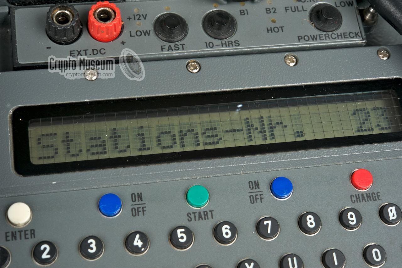
If all is OK (i.e. it passes the self-test) the DSU will ask for your
station number. After entering a 2-digit station number (01-63),
followed by the ENTER key, the unit enters a state machine
with the following structure:
Each state presents itself on the display with a question (in the local
language) which should be answered with YES (white) or NO (red). Pressing
the red button (NO) will enter the next state, whilst pressing the white
button (YES) will enter a dialogue with several sub-states.
Most states are self-explanatory, but entering the cryptographic key is
a bit more difficult.
|
|
FS-5000 will only send messages that are encrypted with a valid encryption
key. Invalid keys are not accepted. Before sending the message,
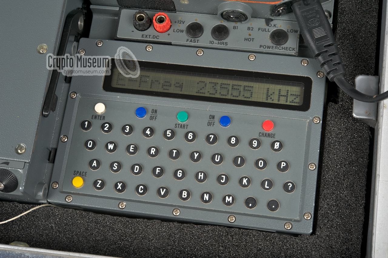
a transmission frequency (TX) and a reception frequency (RX) need to be
specified. The RX frequency is necessary as the station will wait for an
acknowledgement from the base station after the message has been sent.
Below is an example of how to send a coded message. At the left is what
the DSU shows on the display. At the right is what you should type on
the keyboard. [ENTER] is the white key and [CHANGE] is the red key.
|
     Display             Keyboard

     Test-RAM
     Test-EPROM
     Test-Timer
     Test-Krypto
     Stations-Nr.  XX    01[ENTER]

     Empfang     j/n?    [CHANGE]
     Senden      j/n?    [CHANGE]
     Eingabe     j/n?    [ENTER]
     Mel-Sp Eingabe
     Speicher-Nr >  X    1[ENTER]
     TextId>             MSG001[ENTER]
     Sp1 Texteingabe>    THIS IS A TRANSMISSION TEST FOR FS5000[ENTER]

     Empfang     j/n?    [CHANGE]
     Senden      j/n?    [ENTER]
     S-FREQ XXXXX kHz    28020[ENTER]
     Sendeschluessel>    AAAAA AAAAA AAAAA AAAAA AAAAA AAAAA
     Speicher-Nr>   X    1[ENTER]
     TextId>1234         [ENTER]
     Verschluesselung
     E-Freq XXXXX kHz    27500[ENTER]
     Start          j    [ENTER]

     Abstimmung
     Sendebtrieb
     Initialisierung
     Synchronisation
|
The example above can be used to test the transmitter of the
FS-5000. Please note that the message is sent as a short burst,
so the transmitter will be on the air for a very short period of time.
Use the maximum message size (55 characters) to create the longest possible
burst of 0.8s. Before transmission starts, the ATU
first tries to match the antenna (Abstimmung).
This can take up to 3 seconds and is done with an RF-output of less than
5mW in order to avoid detection.
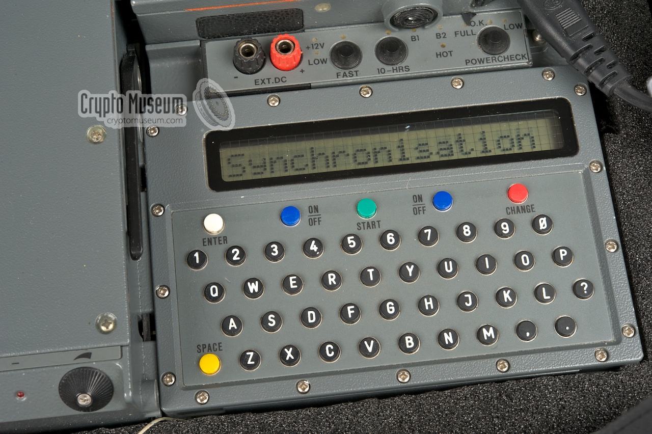
Once the message has been sent (Sendebetrieb), the receiver is activated
(Initialisierung) and the DSU waits for a confirmation fromt the
base station (Synchronisation).
As there is no base station awaiting our transmission, the FS-5000 is
unlikely to receive confirmation and will therefore stay in
SYNCHRONISATION-mode until a timeout occurs (approx. 10 minutes) or the
user presses the START-button.
The actual message (Sp1 Texteingabe) can be anything up to 55 characters.
When the buffer is full, the message Speicher voll (Memory full)
will be displayed. Entering a valid key (Sendeschluessel) can be difficult as
each 5-letter group contains a checksum. This is further explained below.
It works however with the key shown here.
Please note that all messages are lost when the DSU is turned OFF. If you
don't want this to happen, i.e. if you want to retain the messages that are
currently in memory, do not turn the DSU off, but wait until it falls asleep.
In SLEEP-mode the DSU consumes the same current as when it is turned off
(less than 0.19mA). You can wake it at any time by pressing the yellow
SPACE-key.
|
|
In order to encrypt a message prior to transmission, or to decrypt a received
message, a valid cryptographic key needs to be entered. Each key consists of
6 groups of 5 characters each. The letter A-Z can be used and the numbers
2, 3, 4, 6, 7 and 8 (the characters 1, 6, 9, 0, ?, comma and full-stop are
not allowed). The last letter of each group acts as a checksum. As a result
it is nearly impossible to enter an incorrect key group. The following examples
can be used:
|
     AAAAA AAAAA AAAAA AAAAA AAAAA AAAAA
     VBNMN QWER6 ASDFI ZXCV3 TYUIX GHJKO
     VVVVQ QAZPW ZWSXX 3EDCE 4RFV3 OTGBM
|
The key-length is 120 bits which is calculated as follows:
Each character has 32 possibilities, or 5 bits (25).
Of each group, only 4 characters are used for the actual key
(the 5th character is the checksum), giving a total of 6 x 4 = 24
characters. As each of these characters respresents 5 bits,
the total number of key bits is 24 x 5 = 120 bits.
This makes perfectly sense as keys of this size were common
practice in the 1980s and 1990s (e.g. the NSA's
SAVILLE algorithm).
|
|
The interior of the DSU can be accessed by removing 18 small bolts from the
edges of the control panel. This allows the top lid (with the keyboard and the
display window) to be removed. The keyboard is attached to the topmost PCB
inside the unit, by means of a 20-way green connector that can be
removed carefully.
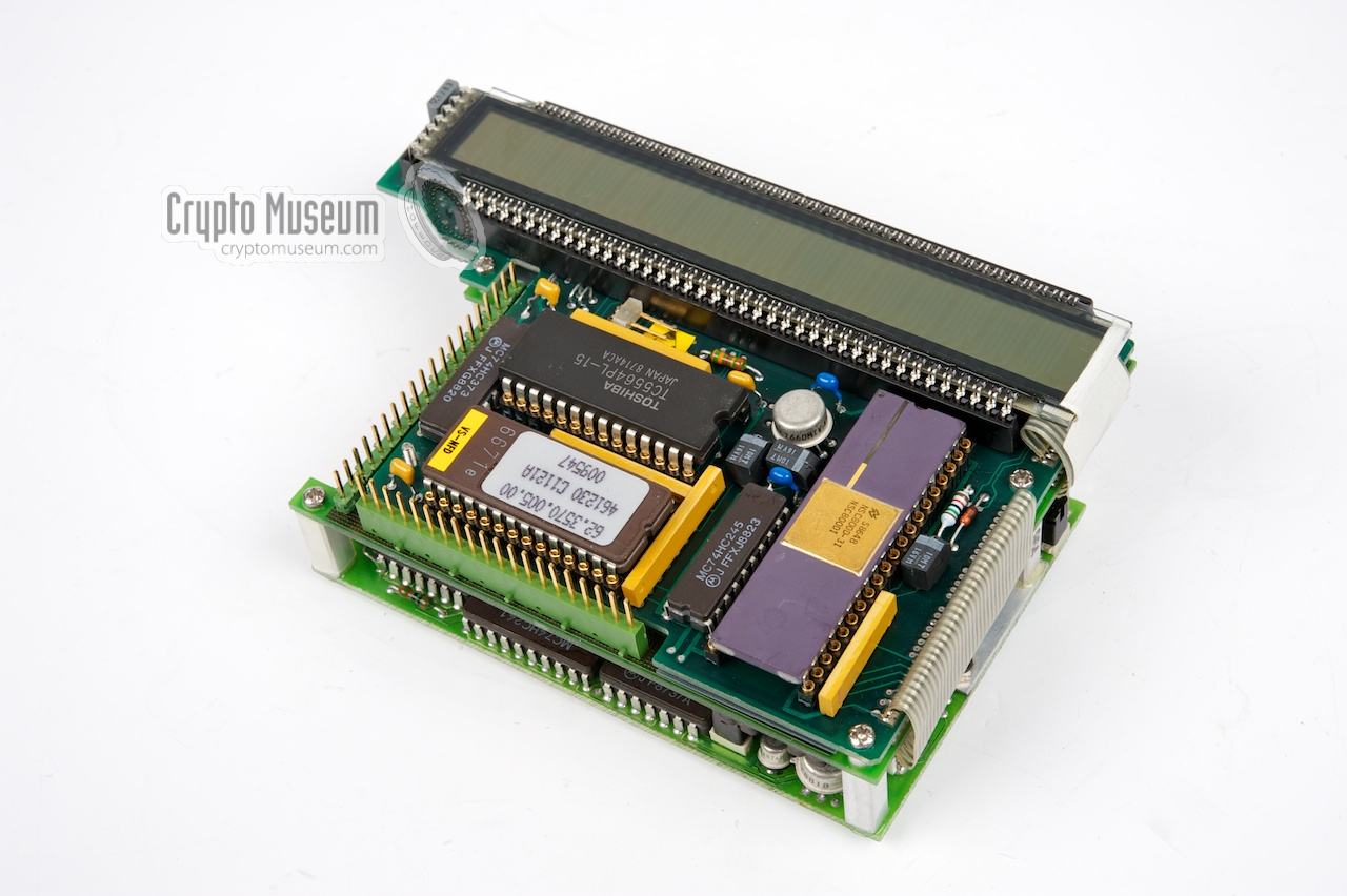
The topmost PCB, holding the main processor (CPU)
is now visible.
|
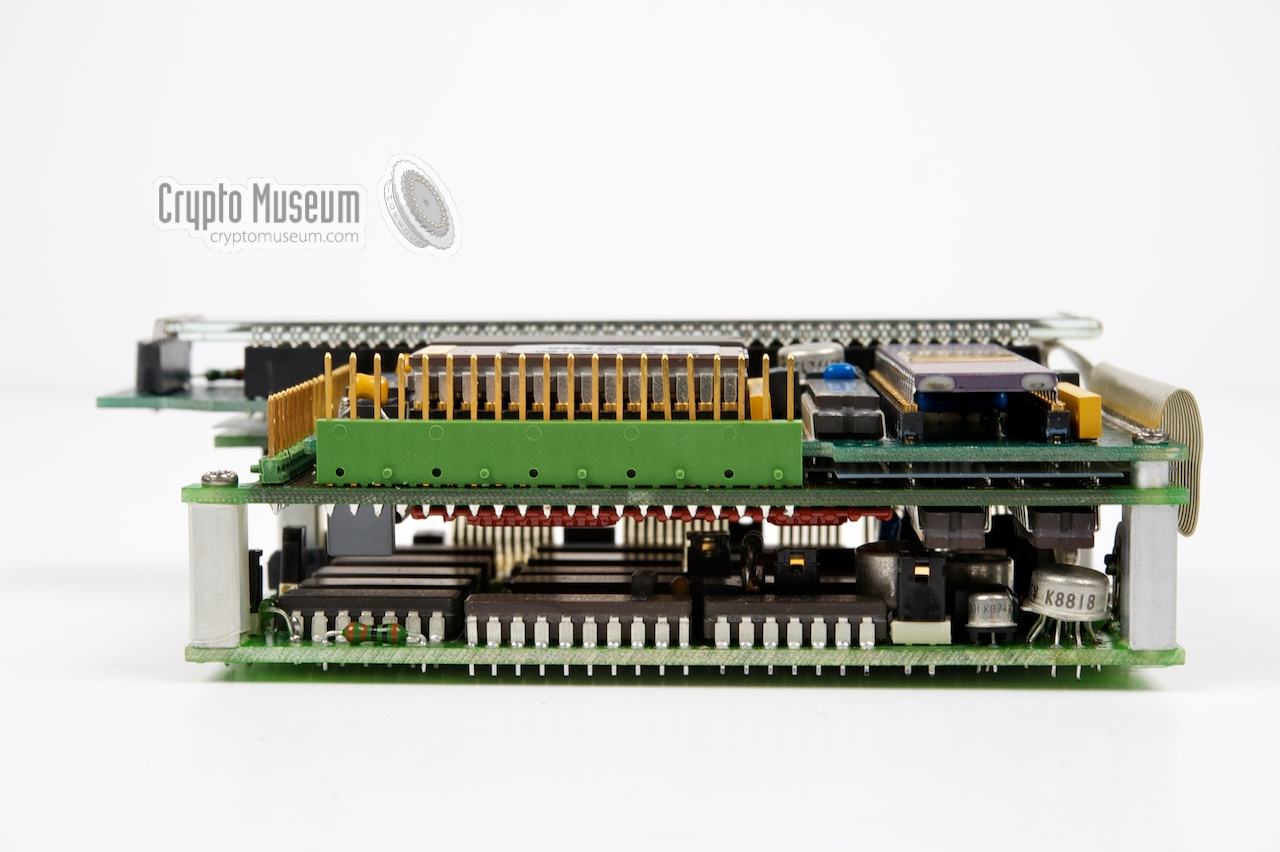
The interior consists of three stacked PCBs that are held together by
a series of small bolts. The complete PCB stack is held in place by 4
cross-head bolts in the bottom of the unit. Removing these 4 bolts will
release the entire stack.
The image on the right shows the interior of the DSU once it is removed
from the case. The three PCBs are interconnected by fixed ribbon cables.
Another 20-way connector at the left connects the PCBs to the external
Sub-D socket. Like the battery plug (bottom), it must be disconnected
before the PCB-stack can be removed.
|
|
|
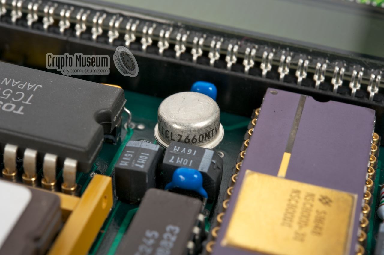
The upper PCB contains the main NCS-800 processor,
which is a mil-spec Z-80 compatible CPU produced by National Semiconductor
[2].
Also on this board are
the EPROM with the firmware, a Toshiba TC-5564PL
[2] static memory
and some 'glue-logic', like the ICL-7660 voltage converter
[4].
The 16-position Liquid Crystal Display (LCD) is also mounted to the upper board.
|
|
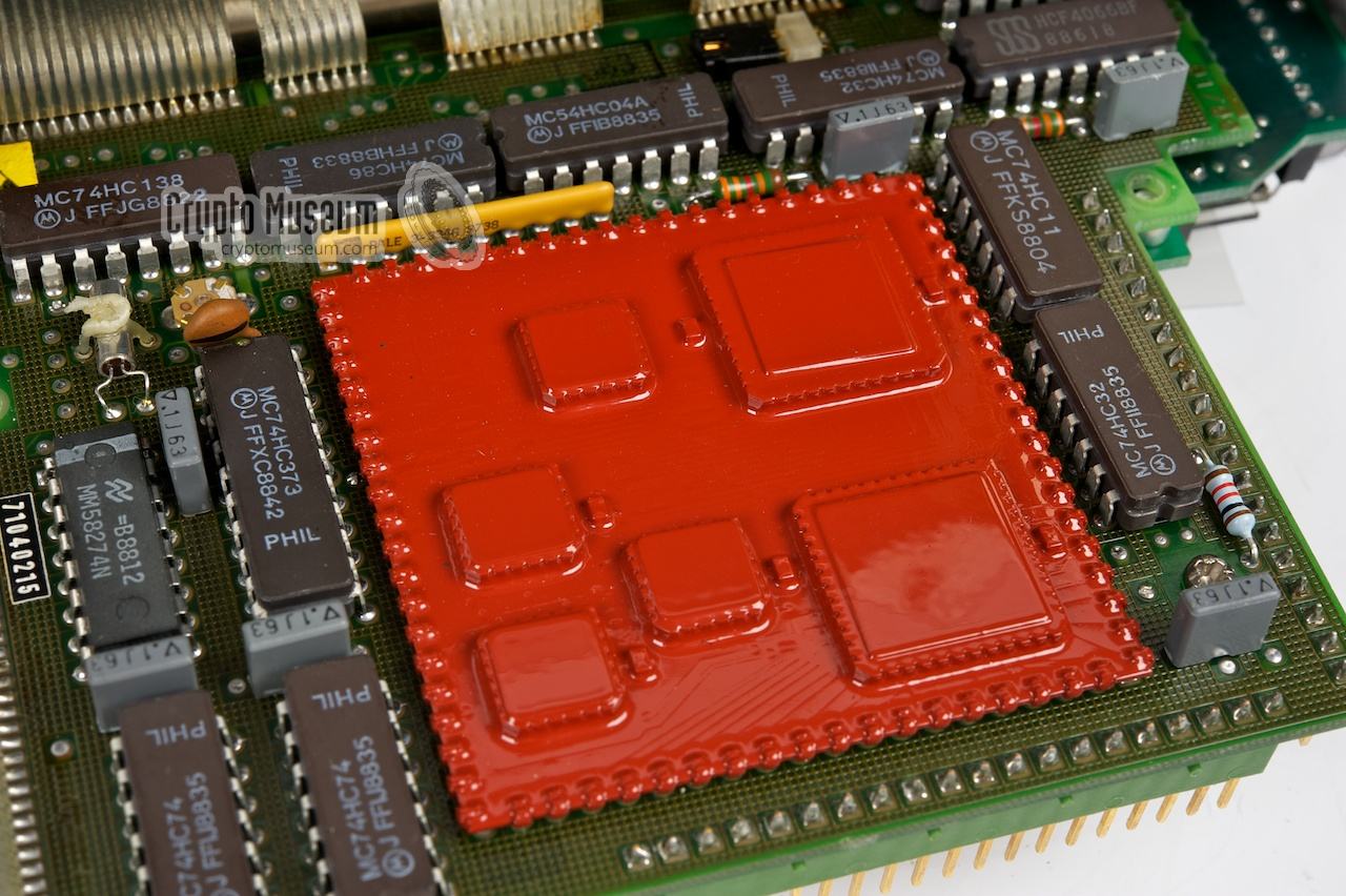
An interesting part is the logic board
that is mounted to the reverse side of the CPU board. At the heart of
this board is a red sub-assembly
that holds two NSC810 peripheral interface devices that control the
keyboard matrix, the lines of the DB25 connector and several timers.
|
|
|
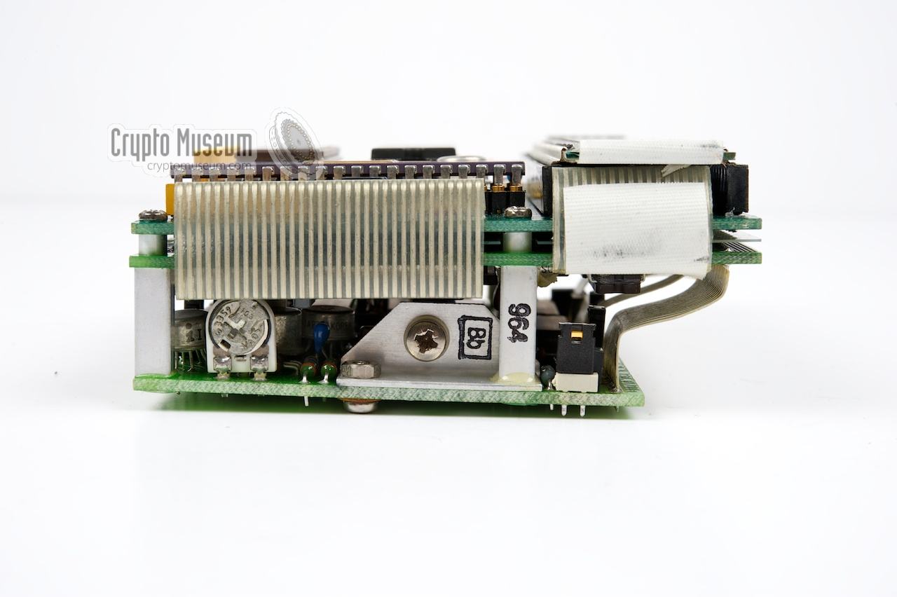
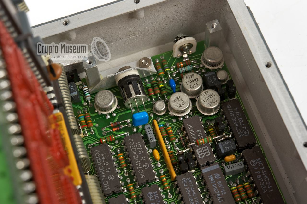
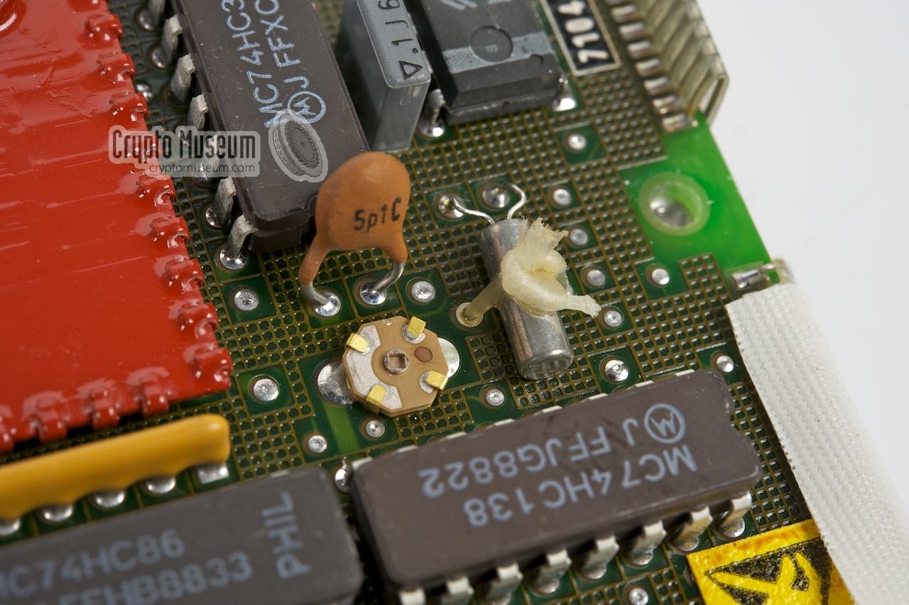
The precise function of the bottom PCB
is currently unknown. It contains several logic ICs and and some analogue
components, suggesting that this might be the actual modulator.
Detailed photographs of this board can be found below.
The 3-pin connector at one corner of the board is used for connection
of the backup battery that powers the Static RAM and the RTC.
|
|
The FS-5000 has been a classified/restricted item for a long time.
It was introduced around 1990, at a time when most countries were forced
to dismantle their stay-behind organisation. The name of the manufacturer
(AEG-Telefunken),
the codename (HARPOON) and the equipment itself were kept secret for many
years, until more and more details became publicly known.
|
In 2005, a small number of FS-5000 stations (approx. 20) unexpectedly appeared
on the surplus market in the US, but were quickly withdrawn when the mistake
was discovered. Unfortunatly, the DSU was missing from the released radio
sets and had probably been destroyed. By the time the authorities had discovered
their fault, approx. 12 units had already been sold to customers.
This led to speculations about the DSU's appearance and functionality, and even
to attempts to create a (functional) replica of the original DSU.
The leftmost image above shows our contribution to the discussion.
In 2009 this was what we thought the DSU might look like.
We now know that we weren't far from the truth, although some questions
remained unanswered at the time.
|
The assumption that the keyboard had circular keys was correct. The keyboard
itself is indeed recessed, but in a different way. Besides, the actual keyboard
has a number of coloured function keys. We speculated about the display
having 2 lines of text with 16, 20 or even 24 characters each, but it turned
out to be a single line of 16 characters only.
Furthermore, the user interface is far simpler than anticipated and the
functionality of the DSU is less than what we had expected.
|
|
After the first FS-5000 sets were released in 2005 without the original
DSU, several people have attempted to create a functional replacement
for the DSU, so that at least transmitter and receiver could be controlled.
This resulted in a PC program and Microchip-based DSU-alternative.
|
The most successful efforts so far were made by Ray Robinson in Australia [7].
Ray started off with a simple interface and is currently working on version
3 of a replacement for the DSU.
Other people have developed different solutions for controlling the FS-5000.
Follow the link below for a more detailed description.
➤ More information
|
|
|
|
|
Barely visible or invisible display
|
|
|
|
In case the display shows very faint text, or shows no text at all,
check the batteries first. The two batteries should together provide
approx. 7V. If they don't, replace them. Note that the AA-size batteries
are specified at 3.7V each, rather than the more common 1.5V.
If this doesn't fix the problem, it is likely that the contrast adjustment
potentiometer inside the device is playing up.
Rotating it back and forth will usually resolve the issue.
To fix this, do the following:
|
- Remove the batteries
- Remove 18 screws from the edges of the front panel
- Take off the front panel
- Disconnect the keyboard
- Disconnect the connector at the left
- Remove the 4 screws from the bottom
- Remove the complete electronics assembly from the enclosure
Pay attention to the power plug - Locate the potentiometer at the right side of the lowest PCB
- Remember the current position of the potentiometer
- Clean the potentiometer with a drop of high-quality contact cleaner
- Rotate the potentiometer back and forth a couple of times with a screwdriver
- Put the potentiometer back in its original position
- Place the assembly back in the enclosure (mind the power plug)
- Replace the 4 screws at the rear
- Reconnect the connector at the left
- Reconnect the keyboard
- Reposition the front panel
- Fixate the front panel with the 18 screws
- Install the batteries
- Test the unit
|
Device Digital Storage Unit (DSU) Purpose Control, message storage, scheduler, encryptor for FS-5000 radio station Model SR-5000 Codename Harpoon Manufacturer ANT Backnang (Germany) Year 1988 Country Germany Algorithm Proprietary, firmware-based, NATO-approved Messages TX: 10, RX: 10 Size TX: ≤ 55 chars, RX: ≤ 52 chars Characters 6 bit Power see below Dimensions ? Weight ?
|
Power 7V DC Source 2 x AA-size 3.5V Li-battery On < 40mA Stand-by < 0.19mA Off < 0.19mA
|
Power 13-20V Source FS-5000 (via receiver) On < 42mA Stand-by < 0.35mA Off < 0.35mA
|
- Crypto Museum, FS-5000 radio station with DSU
Investigation at Crypto Museum. April 2012.
- National Semiconductor, NSC800 High-Performance Low-Power CMOS Microprocessor
June 1992. Retrieved April 2012.
- Toshiba Semiconductor, TC5564 - 8192 x 8-bit CMOS static RAM
Date unknown. Retrieved April 2012.
- Maxim, MAX1011/ICL7660 datasheet
19-4667, Rev 1, July 1994. Retrieved April 2012.
- National Semiconductor, MM-58274C Microprocessor Compatible Real Time Clock
April 1991. Retrieved April 2012.
- Helmut 'Jim' Meyer, HS0ZHK, My way to Ham - Radio and beyond
Website QRZ.COM. Personal correspondence.
Retrieved June 2008.
- Ray Robinson, Digital Control Unit (DCU)
DSU replacement with Microchip. Started 2005. Last changed February 2010.
Retrieved May 2012.
- Operators Manual for PC-KAYSAT-KAYNARD-RACE Software
Instructions for the NL-developed message and encryption handling software (English).
May 1991. SECRET.
|
|
|
|
Any links shown in red are currently unavailable.
If you like the information on this website, why not make a donation?
© Crypto Museum. Created: Friday 01 June 2012. Last changed: Monday, 08 June 2026 - 11:06 CET.
|
 |

|
|
|