|
|
|
|
|

|
|
Rotor USA NSA KL-7 Toolkit →
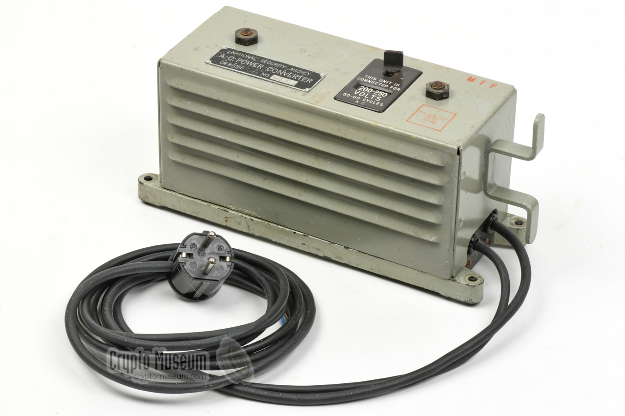
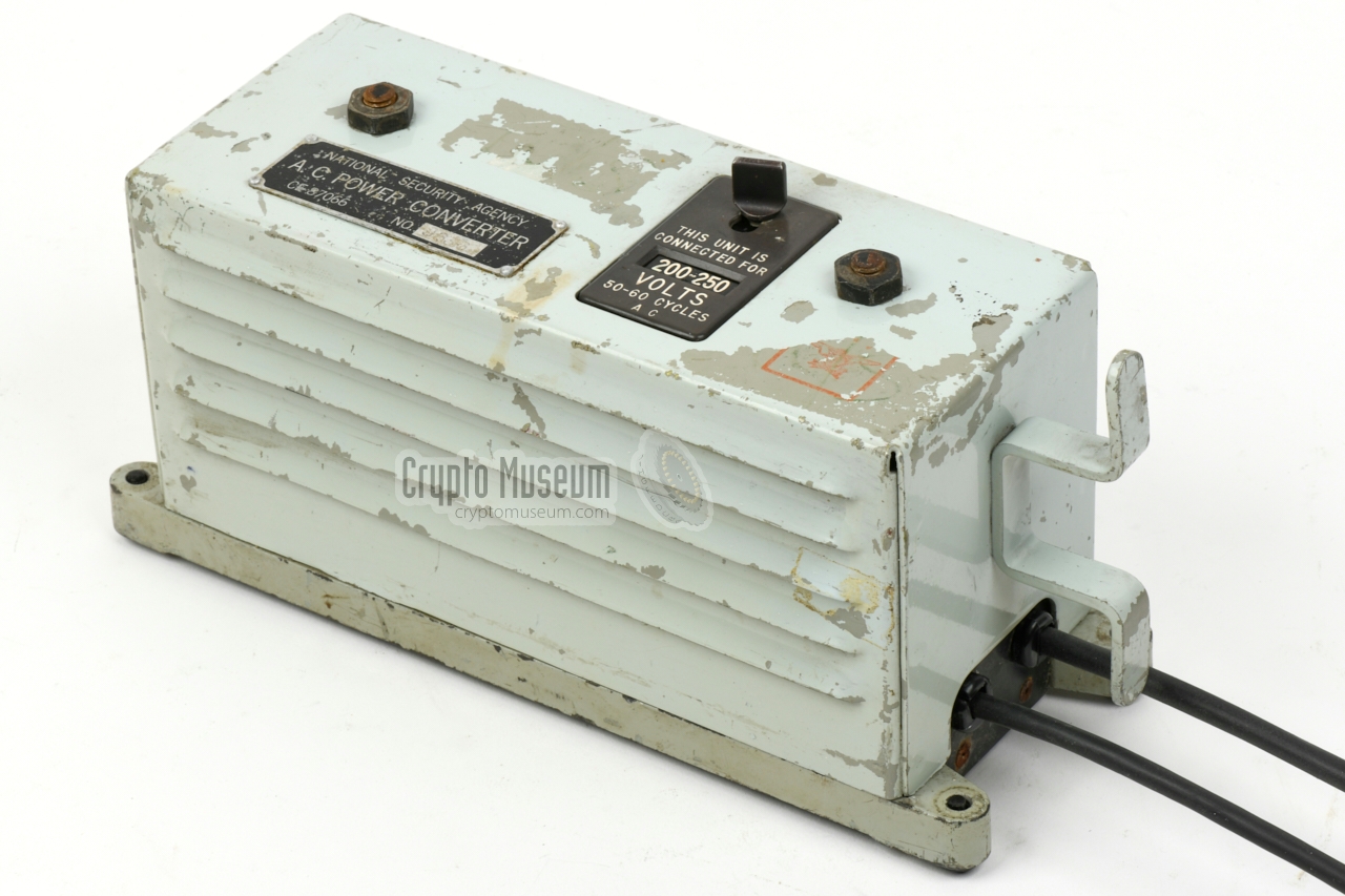
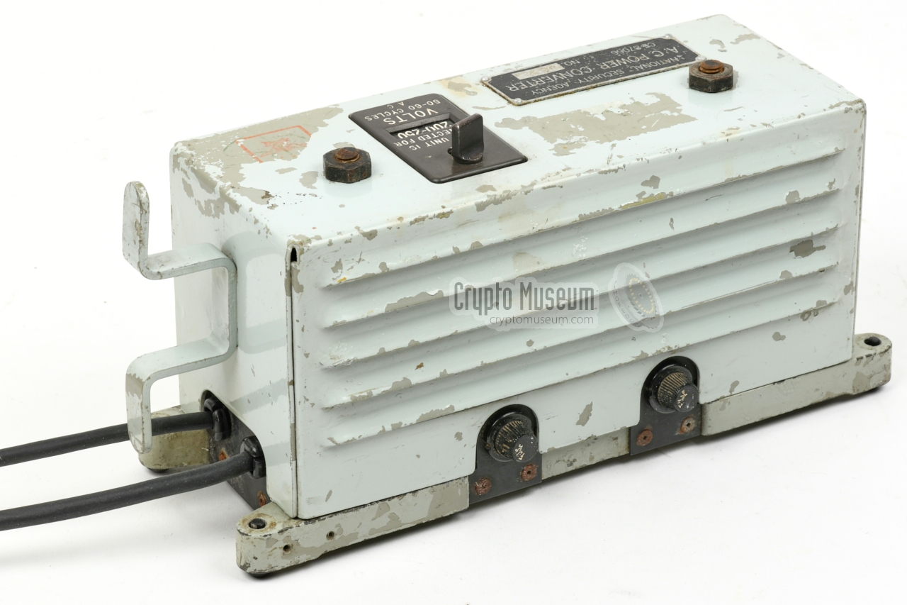
Power Supply Unit · CE 87066
When used in a static environment, such as an office or a command centre,
the TSEC/KL-7 cipher machine was usually powered directly from the
AC mains, using the external power supply unit (PSU) shown below.
It is suitable for 100-125 V AC and 200-250 V AC, and delivers
~ 24V DC.
|
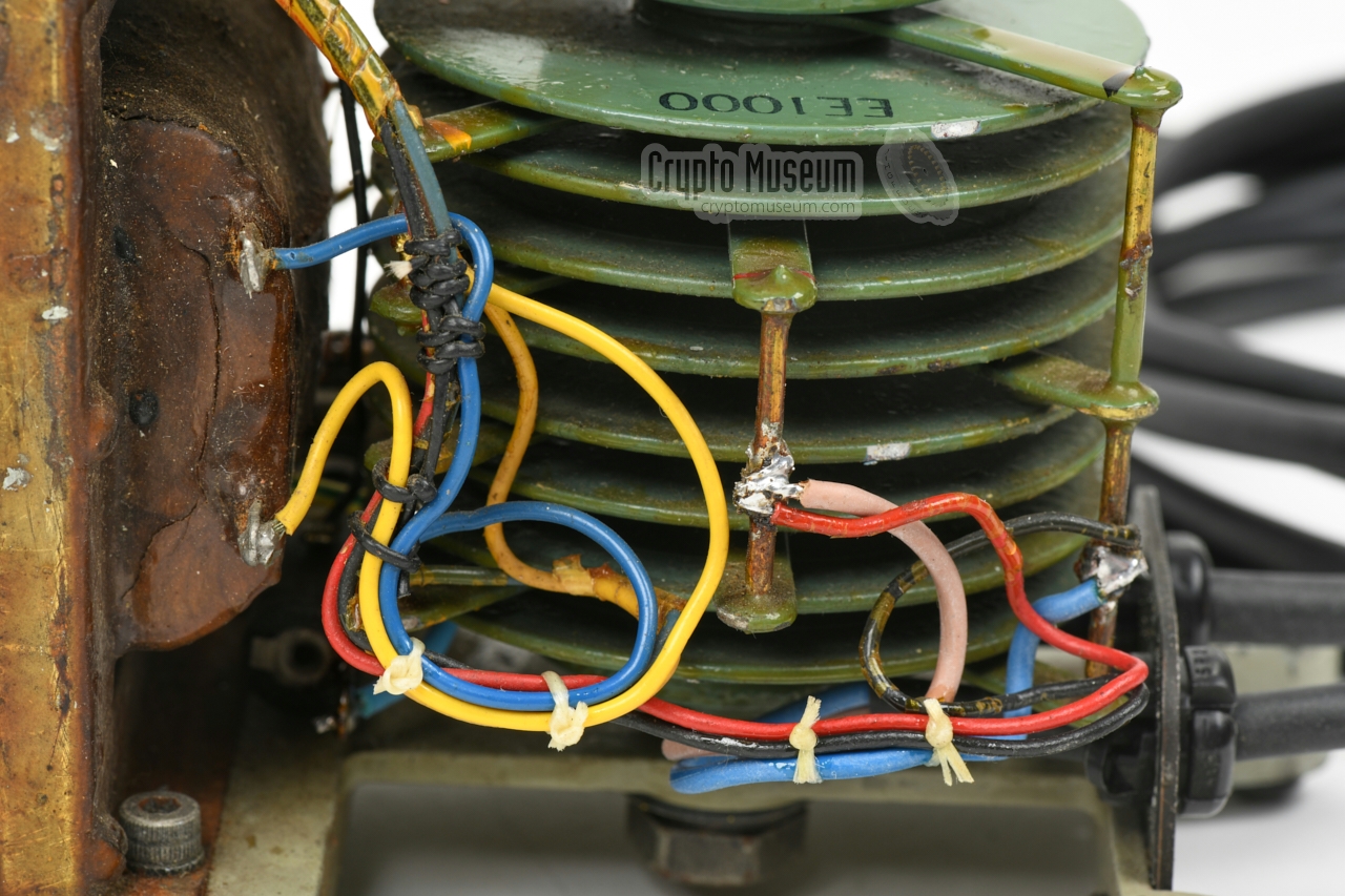
Below is the circuit diagram of the power supply unit, which consists of
a conventional mains transformer and a full rectifier. The transformer has two
identical primary windings, that are connected in parallel when configured
for the 100-125V AC mains, and in series for the 200-250V AC network.
The voltage selector is connected at the centre of the primary windings.
The secondary side of the transformer delivers 17-24 V AC, which is rectified
by the two stacked full-wave selenium cells at the right. In practice, these
selenium cells are
mounted at either side of the transformer.
Although there are
two fuse holders at the rear of the device,
only one is used in the
primary circuit. The other one holds a spare fuse. The mains ground wire
is not present, but was added by us for safety reasons. It is connected
to the chassis of the device (see below).
|
|
The KL-7 power supply unit featured on this page, was found on eBay in
late 2020, and was in unknown state when it arrived. The exterior was
painted in a light blue (near mint) colour, similar to the colour that
was used by the US Navy. There were several self-adhesive labels on the
body, that had clearly been added by a later owner.
The base of the unit still showed the original paint.
|
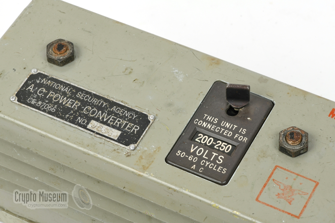
The unit had probably been stored in a dusty moisturous place for many
years, as the text on the name tag and the voltage selector was barely
readable. A first superficial cleaning revealed that the text on the
selector was still legible.
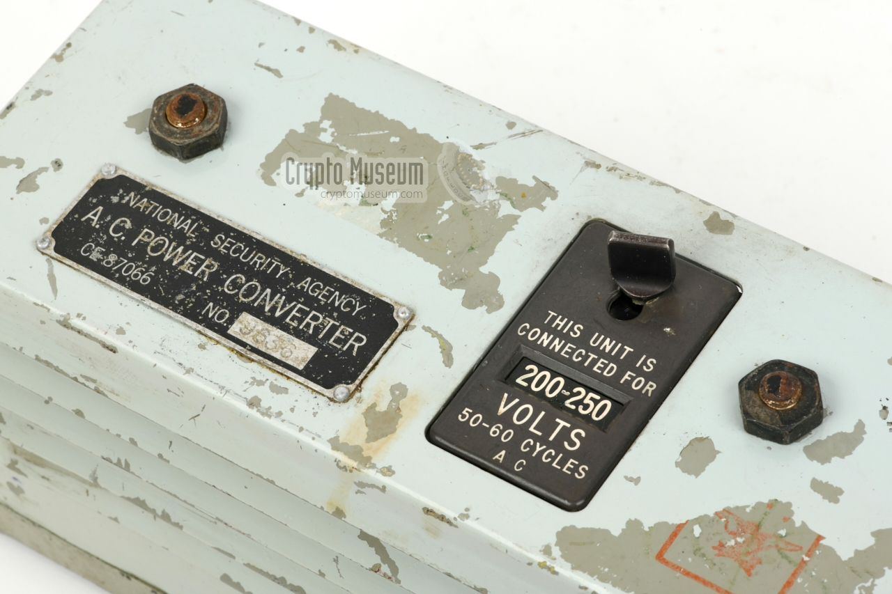
When removing the unwanted self-adhesives from the top surface, they
took some of the paint with them, as shown in the image on the right.
Although this was initially regarded as unfortunate damage, we later discovered
the original red stamp in the bottom right corner
and concluded that that was the original paint.
|
|
|
|
Apparantly, the exterior had been repainted at some stage – by the US Navy
or by a later owner – without properly cleaning the surface first. As a
result, chips of the new paint easily came off. We then decided that it would
be best to remove all of the later paint and restore the original colours.
|
That was easier said than done. Although the paint easily came off from the
top surface, there were other places where it was more persistent.
This was especially the case at places where the original paint had been damaged in the past.
First, the loose chips were removed by putting wide cellotape over it, and then
pulling it off. The remaining paint was removed manually, using the finger
nails and several special tools. The result is visible in the image on the
right. Even the red eagle and the red Moisture and Fungus Proof stamp
(MFP) are still fully intact.
|
|
|
|
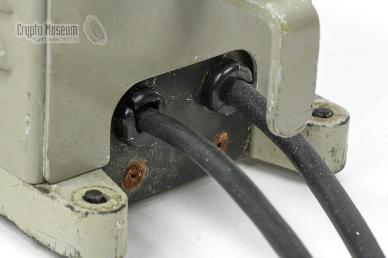
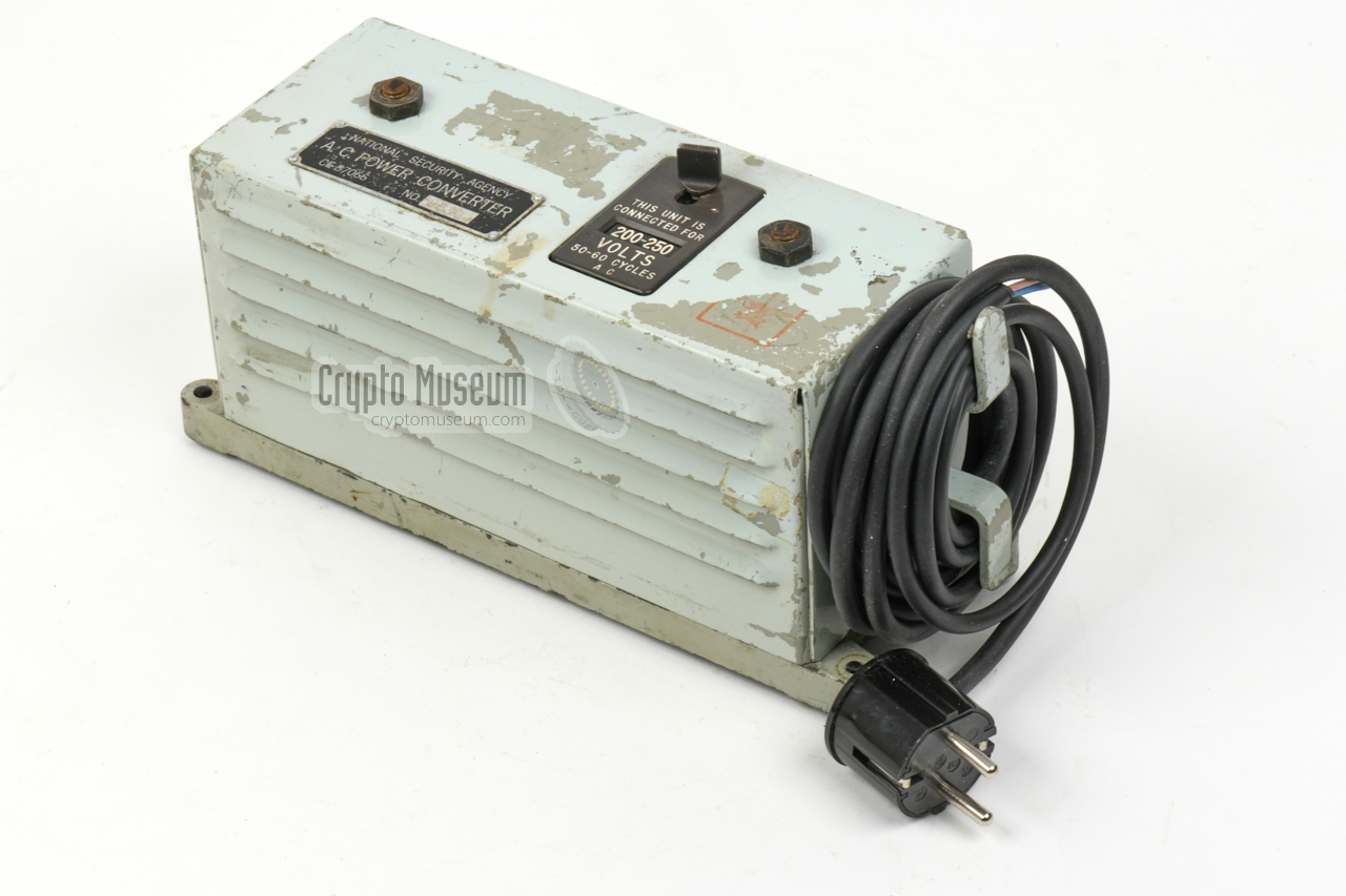
The original rubber power cables had become stiff and brittle over the years,
and were no longer considered safe for connection to the mains network.
They were both removed and were replaced by modern neoprane cables,
from which the printed yellow text had been removed with acetone.
|
Along with the wiring, the strain reliefs – that had meanwhile completely
disintegrated – were replaced by nearly identical new plastic ones.
For safety reasons a ground wire was added between the mains ground and
the chassis — something that was not present in the original design.
After fitting a new mains plug, the pins were checked for continuity and the
primary and secondary sides of the transformer were checked for resistance.
Once we were certain that the device would not short out or cause a ground
leak, it was connected to the 230V AC mains.
|
|
|
It worked straight away and approx. 26V DC was available on
the unloaded output termials.
Next, the KL-7 was connected to it, and its
MODE-selector was set to plaintext (P).
After warming up, everything worked as expected. In this situation
the voltage had dropped to 24V DC as expected.
The following was restored:
|
- Mains AC power cable replaced
- DC output cable replaced
- Both strain reliefs replaced
- Voltage selector cleaned
- Several wiring junctions resoldered
- Rubber feed added to the threaded mounting holes
- Light blue paint removed and original paint restored
- Power connector replaced
- Tested with KL-7
|
|
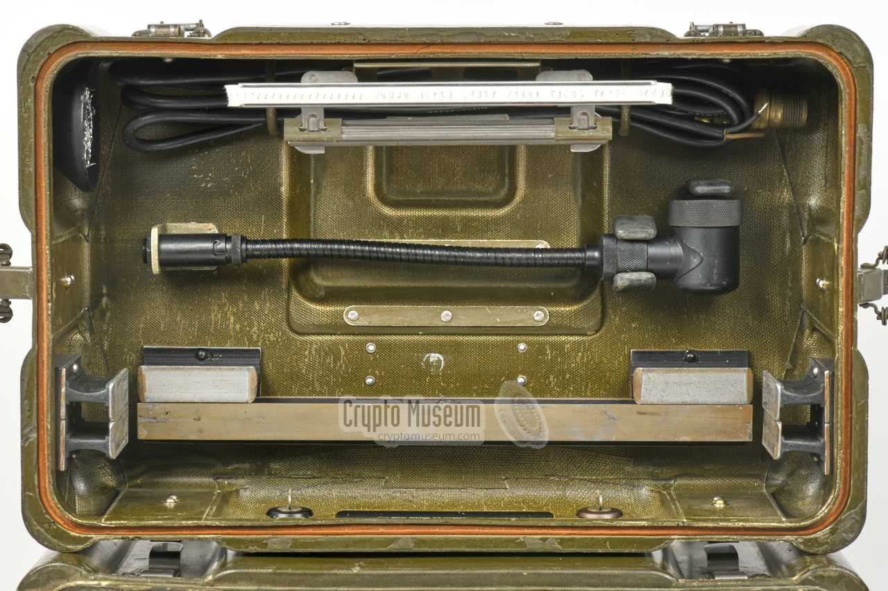
The KL-7 must be powered by a 24V DC source, that should be connected
to the short piece of cable to the right of the keyboard. It has a 2-pin
Amphenol 97-series (male) plug at the end, that mates with the 2-pin
(female) socket on the power cable (stowed in the
case lid) and on the
external PSU. The required (female) socket has the following part
number: Amphenol 97-series MS3101A12S-3S (shell: AN3057-4).
Below is the pinout of the (female) socket on the PSU:
|
|
|
|
Any links shown in red are currently unavailable.
If you like the information on this website, why not make a donation?
© Crypto Museum. Created: Sunday 18 April 2021. Last changed: Wednesday, 05 November 2025 - 11:56 CET.
|
 |

|
|
|


