|
|
|
|
|

|
|
← TST Voice
Voice and data encryptor
The 7700 was a voice encryption device, developed by
Tele Security Timmann (TST)
in Tützing (Germany) around 1984. The device is suitable for secure voice
conversations, data transmissions and (optionally) fax transmissions.
It provides high-end encryption with a choice of vocoders and
encryption algorithms and is housed in a military-grade cream or green TEMPEST enclosure.
|
The TST-7700 was designed for use at the highest level of secrecy and
was suitable for voice and data communication. It was completely operated
from the connected telephone set (using DTMF tones) and offered voice
encryption without loss of quality. Furthermore, it could be used
on bad quality telephone lines, with graceful degrading of the voice
quality.
When used over satellite links, the delays, that are typical for such
connections, did not affect the encryption. For data communication,
a 25-way RS-232 connector was available at the front.
|
|
|
The TST-7700 is suitable for voice data at 2400, 4800 and 9600 baud
and uses synchronous communication. Computer data can be transferred
(asynchronous) at any speed between 1200 and 19200 baud. The device was normally connected between the telephone set and the line, but it was
also possible to protect an entire office by placing it between the
PABX and the line [2].
The TST-7700 was later replaced by the TST-7790 that was housed in the
same enclosure and had the same physical appearance. Contrary to the
TST-7700, which had to be powered externally, the TST-7790 had a suitable
mains power supply bolted to the rear of the unit [2].
|
The TST-7700 has no controls; it is fully controlled from the
conected telephone set. At the front panel are three D-type
sockets that are used for the connection of the telephone set,
the line and (optionally) a computer via the standard
RS-232 serial port (also known as the COM-port).
The coloured dots above the connectors indicate the RED and BLACK
sides of the unit. The telephone set and the computer are both
RED devices as they handle plaintext. The encrypted data is present
at the telephone line, which is therefore said to be the BLACK side.
Power is supplied to the unit via a
9-way connector at the rear.
The pin-out is currently unknown.
|
Cryptograpic keys were loaded into the TST-7700 by means of a
dedicated key loader, known as the TST-0706, that was connected
to the 25-way D-type socket at the front panel. The same connector
that was used for connection to the RS-232 port of a PC.
Photograph taken from [2].
The image on the right shows the TST-7790 with the TST-0607 key
loader attached at the front. They key loader itself carries a
TST-0502 memory card that holds the actual keys in encrypted format,
as generated by the propiretary TST Key Production Center.
The keys are fully encrypted themselves, in order
to avoid compromise in case they are lost in transit.
|
|
|
The TST-7700 was later replaced by the slightly enhanced TST-7790.
It had nearly the same features and had the same connections at the
front panel, but had a mains power supply bolted on at the rear [2].
The image on the right shows a TST-7790 unit as is was printed on
the front page of the brochure [2].
|
|
|
|
The TST-7700 is extremely well built. It is housed in a case that is
similar to the enclosure of other TST devices, such as the
TST-4043, but it is much better shielded against
unwanted EMC/RFI emission (TEMPEST). RF shielding is further improved
by the use of RF gaskets.
|
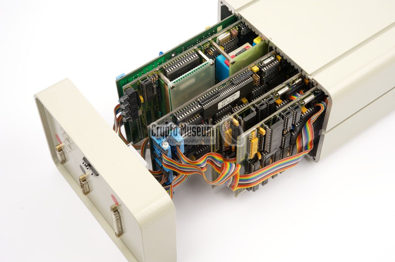
The unit can be accessed by releasing 4 long bolts at the corners of
the front panel, after which the heavy front panel can be removed.
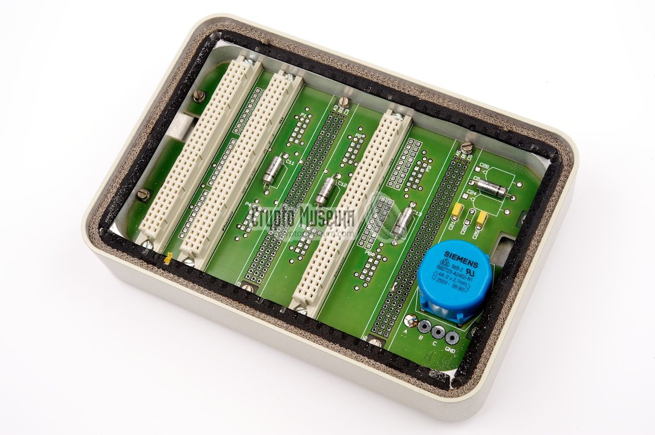
Inside the unit are five extremely well designed PCBs, three of which
are slotted into a backplane
that is mounted to the rear panel.
The remaining two boards (i.e. the rightmost two boards) are held in
place by metal brackets and are connected to the other boards by means
of flat-cables. The leftmost three board are connected via the backplane,
but also via additional flat-cables that are mounted at the front side.
|
|
|
The leftmost board
is the interface to the connected telephone set
(i.e. the RED side). It is built around a so-called SLIC (Subscriber
Line Interface Circuit); a
pre-fabricated ceramic carrier board
manufactured by Mitel that allows virtually any type of telephone
set to be connected [3].
|
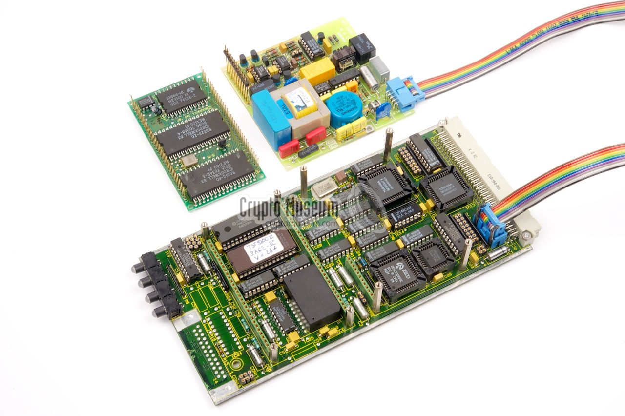
The cryptographic keys are retained in a voltaile memory that is powered
by an internal Li-ION battery. By breaking the
power to the volatile memory (using the tamper switch), the keys are
deleted. The rightmost two boards are the vocoders.
As the device can be used for full-duplex, two identical vocoders are needed:
one for sending and one for receiving. The vocoders are not slotted into
the backplane at the rear, but are directly connected to the digital board.
|
-
Brochure kindly supplied by Helmuth (Jim) Meyer [1].
|
|
|
|
Any links shown in red are currently unavailable.
If you like the information on this website, why not make a donation?
© Crypto Museum. Created: Tuesday 02 July 2013. Last changed: Tuesday, 18 March 2025 - 08:50 CET.
|
 |

|
|
|