|
|
|
|
|

|
|
USA TCC Scrambler
EDT voice scrambler
DSP-9000 is an Enhanced Domain Transform (EDT)
voice scrambler, 1
developed around 1991 by
Technical Communications Corporation (TCC)
in Concord (MA, USA). It's improved miniaturised version
of its predecessor – CSD-909 – built with DSP technology.
As the device works within the 3 kHz audio
passband, it is suitable for communication over HF, VHF and UHF
radio networks.
|
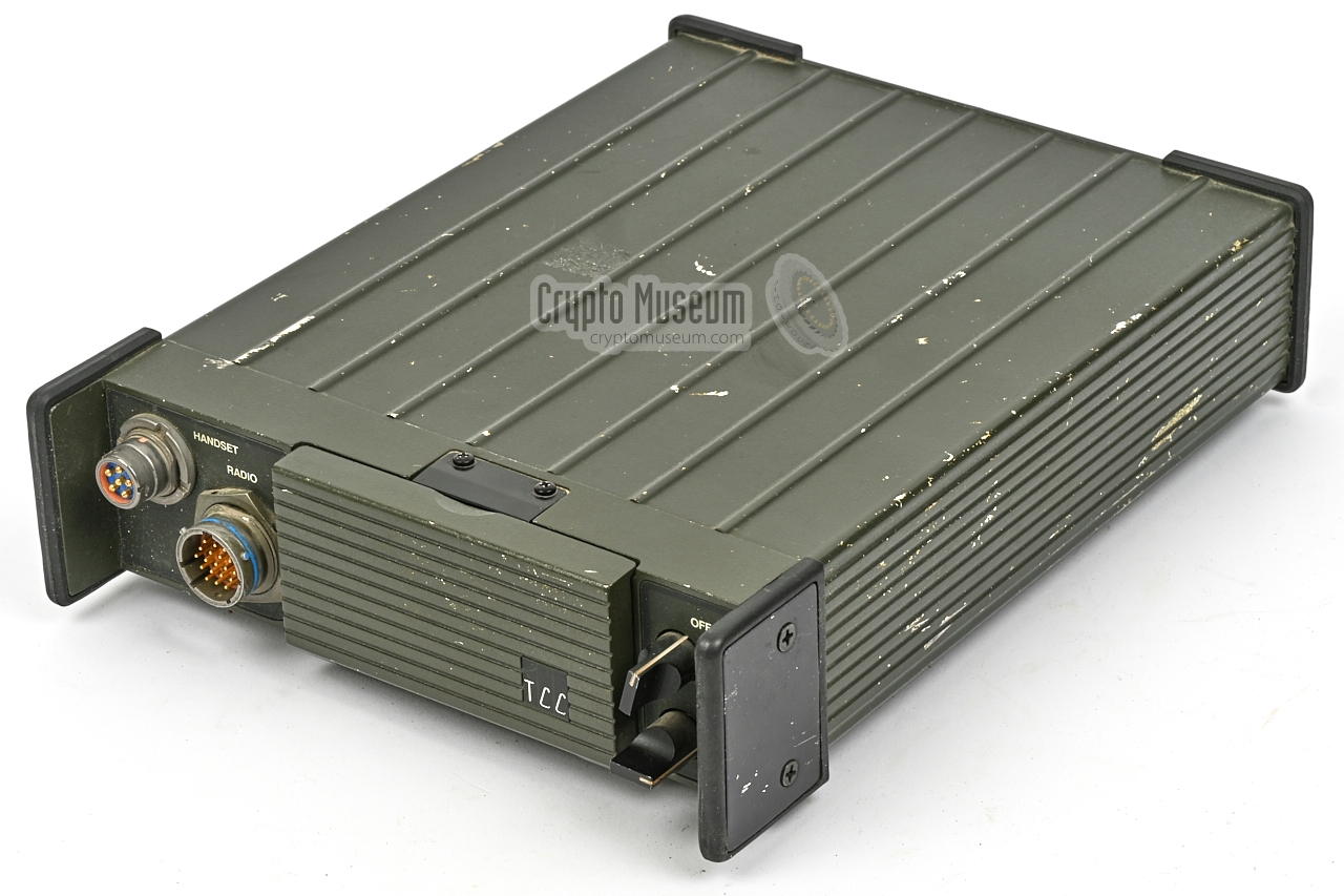
The device is housed in a green rugged die-cast aluminium enclosure that
measures 280 x 215 x 88 mm and weighs 2.7 kg.
All connections and controls are at the front panel, with a hinged
keypad covering the Liquid Crystal Display (LCD).
The device is available in a number of variants, such as a base station,
a handset and as an embeddable module, and could be modified for a wide variety
of military HF transceivers. The device shown here is the base station
variant, which in this case is suitable for connection to the
Transworld RT-7000 HF transceiver.
|
|
|
|
DSP-9000 units were typically used in South-American countries, but also in
(neutral) Austria.
In 2007, 2009 and 2013 it was announced that Afganistan's military had
placed large orders
for DSP-9000 equipment for its radio networks. The order consisted of
handsets and implant boards, that would be supplied
through Datron World Communications Inc., which also supplied the radio
equipment itself to the Afgan forces [1][2].
The DSP-9000 was still available for sale in 2024 [1].
|
PLEASE HELP —
We are still looking for user manuals and technical manuals of his device.
If anyone has further information about this device, or has documentation
that is not listed here, or wants to share stories about the use of the device,
please contact us.
-
Prices in US$, taken from Datron GSA pricelist, March 2019.
-
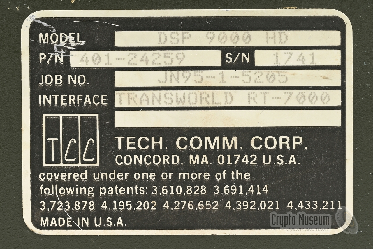
The serial number label identifies it as DSP-9000 HD, but it is in
reality a DSP-9000 RC.
|
The image below provides an overview of the controls and connections at
the front panel of the DSP-9000. At the top left is a regular US/NATO
receptacle for connection of a handset, headset or other type of
microphone/speaker combination. To its right is a 19-pin receptacle
that carries the red and black interfaces plus the interface for an (optional)
remote control unit. It should be connected to the external military
transceiver, which in this case was a Transworld RF-7000.
At the right are two rotary MODE selectors. The upper one acts as the power
switch. It has four positions and selects between PLAIN, Secure (CIPH) and
Command (CMD) modes. The other one has three positions, one of which (SYNC)
is momentary. It is used to synchronise the equipment at the beginning of a transmission. At the centre are the Liquid Crystal Display (LCD), which can
be covered by a hinged 24-button keypad. To the left of the LCD is a
9-pin DE-9 socket for connection of a key loader. Above the
socket is an LED indicator for the audio level.
|
The DSP-9000 RC model uses the same chassis as the DSP-9000 HD.
The major difference is the lack of a RADIO connector at the front panel
and the addition of a remote control head at the rear. It make
the RC model 5 cm longer and provides the
RADIO connector at the rear.
Furthermore, two LEDs have been added to the
front panel: one for PLAIN
and one for CIPHER mode.
The image above shows the DSP-9000 RC with its hinged keypad open and a
regular H-250/U handset connected to the
U-229 audio connector at the front.
A SmartModule (SM) is installed in the
9-pin DE-9 socket to the left of the
Liquid Crystal Display (LCD). The SM can be used to transfer up to
200 keys and other configuration parameters to and from other DSP-9000 units.
|
TCC is particularly vague about the
exact technology it uses for securing speech.
In the brochure it is
claimed that the device features an
Enhanced Domain Transform (EDT) algorithm, controlled by
a highly non-linear digital key stream generator [A].
Each group of devices has a fixed internal System Key,
which is different for each customer. In addition,
TCC also offers tools for algorithm customisation, suggesting
that the customer has some control over the algorithm.
Unfortunately, the manufacturer does not explain what EDT is
and gives no details about the key generator.
Although the device is digitally controlled — the key stream is
generated digitally, and processing is done in the digital domain —
the nature of the device is analogue. Voice data
is digitised and then transformed using three different
DSP-based techniques, after which it is converted back to the analogue domain (audio).
The resulting signal has the same 3 kHz bandwidth as the orginal voice signal
which means that it can be transmitted over existing
narrow-band radio channels.
The 6 patent applications listed at the
back of the device are not
very helpful either. They all refer to older techniques of which it is
doubtful that they are used in the DSP-9000.
Furthermore, one of them (3,691,414) is clearly a misprint as it refers
to an unrelated subject.
The last one is from 1981 and describes
a two-dimensional scrambler that operates in the
frequency and time domain (F/T).
This technology is also used by
other manufacturers and is known to
be vulnerable.
As with any voice scrambler, the fact that the keystream
is highly non-linear and that digital processing techniques are used in the
scrambling/descrambling process, doesn't mean that it is secure.
|
Although the manufacturer does not explain how the scrambling
algorithms works, some of its characteristics have meanwhile
come to light. The algorithm of the DSP-9000 is virtually
identical to that of the earlier CMOS based CSD-909.
Although it operates solely in the analogue domain, it does
have a unique property to complicate waveform analysis.
The description below comes from a former expert [3] who
worked with the DSP-9000 for many years and recalls the following:
The audio frequency band is split into 8 sub-bands of 300 Hz each (I-VIII),
with a guard band at either side (for simplicity not shown here).
Each sub-band is then transposed
to a 300 Hz baseband — as shown in the example below for sub-band III —
after which it is sampled:
The samples are then stored in a memory buffer
in a pseudo random pattern that transposes their place in the
sub-band order (i.e. the frequency domain), as well as their place
in time (i.e. the time domain). In addition, some samples are stored
in forward order, whilst others are reversed [3].
The pseudo random order changes continuously under control of an
internal key generator (the algorithm) that is seeded with an
initialization vector (IV) at the start of each transmission.
The algorithm also determines how many samples
are combined into a 'frame'.
Shuffling in the time domain occurs at sub-syllabic intervals to avoid
recognition of (part of) words. Shuffling in the frequency domain occurs
per frame in intervals of more than one second. When combining these two
techniques, it becomes virtually impossible to recognise a cadance in
the cipher stream, regardless of whether sentences are spoken slowly or
at a higher rate.
The diagram above shows what the 2-dimensionally transposed signal may look
like. Once the samples of a given interval are stored in memory, they are read
out at 8× the speed in order to reconstruct the 3 kHz bandwidth of the
original signal. The diagram below shows how the signal in
band III — created from the samples in memory — has changed from its original shape.
|
|
At the beginning of each transmission – i.e. when pressing the
push-to talk (PTT) switch – an initialisation vector is sent
to the DSP-9000 at the receiving end, so that both devices
are synchronised and produce the same key stream. The descrambling
process is just the reverse of the scrambling process described above.
|
When observing the output from a DSP-9000 device, it becomes
clear that most of the energy of the signal is located in a 300 Hz
segment just below 3 kHz (i.e. 2700-3000 Hz). This is what produces
the typical sound transmitted by a DSP-9000.
|
The diagram below shows roughtly how the signal is sampled (ADC), after
which the eight sub-bands are filtered, mixed (i.e. transposed), filtered
again and stored in memory.
The samples are then shuffled under control of a key generator (KG).
Next, the samples are taken from memory, mixed (i.e. transposed to the
destination sub-band), filtered, combined and converted back into and analogue
signal (DAC), Note this is not built with discrete electronics as in the
CSD-909 predecessor, but rather
with firmware in a Motorola DSP56001 Digital Signal Processor (DSP).
The mixing stages — both in the input and in the output circuits —
are each fed with a different fixed frequency f1 to f7, except
for the baseband itself (I).
In the input circuit this converts each of the sub-bands to the
300 Hz baseband. In the output circuit it transposes the individual
audio channels back to the original sub-band. The mixer frequencies
are assigned as follows (f):
|
| f1 | f2 | f3 | f4 | f5 | f6 | f7 |
| 400 Hz | 800 Hz | 1200 Hz | 1600 Hz | 2000 Hz | 2400 Hz | 2800 Hz |
|
The heart of the system is the actual DSP-9000 voice scrambler.
The basic DSP-9000 HD model has all controls and
#conn) at the front panel.
It can be wired to a (military) radio set.
The DSP-9000 RC model shown in the image on the right, has the
same controls, but has the RADIO connector at the rear.
It allows the unit to be wired to a remote control unit, a
(military) radio or an analog telephone system. It was supplied
with a long break-out cable.
|
|
|
|
|
Smart module (key fill device)
|
|
|
The DSP-9000 comes with a so-called SmartModule, which is
housed in a 9-pin DE-9 plug. It is used for transporting
and loading up to 200 Local Keys or other DSP-9000 configuration data.
It is also known as a key transfer device.
The SmartModule should be
connected to the DE-9 socket at the
front panel of the DSP-9000. Note that the keyboard must be opened
before the module can be installed. It can be removed once the
keys have been transferred.
|
|
|
The DSP-9000 HD and RC models can be used with virtually any
regular handset with U-229 connector. Such
handsets usually have a dynamic microphone.
It is also possible to use handsets with a carbon or an electret
microphone, but this requires the microphone bias feature to be
enabled first. This is done from the device's menu.
➤ Pinout of the handset connector
|
|
|
The DSP-9000 can be connected to most types of (military) radio
by means of a suitable radio cable. Such cables are usually customised
for a particular radio type. The cable shown in the image on the right
is a universal one that can be made to work with virtually any type
of radio or (analog) telephone set.
The cable should be connected to the RADIO connector at the front panel
of the DSP-9000 HD or, in case of the DSP-9000 RC, at the rear.
➤ Pinout of the radio connector
|
|
|
In case the DSP-9000 is remote controlled, the device was usually
supplied with a remote control head that is bolted-on at the rear.
In that case the RADIO connector is missing from the front panel
and is located on the add-on.
The image on the right shows the rear of a DSP-9000 RC, of which
the remote control head has been separated.
➤ Pinout of the radio connector
|
|
|
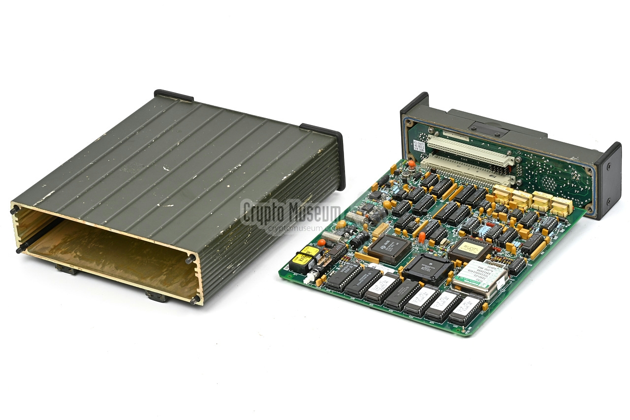
The interior of the device can be accessed by loosening the four long bolts
at the corners of the rear panel, after which the case shell can be removed.
This reveals the interior, which consists of a front panel and one or two
printed circuit boards (PCBs) that are plugged into the front panel.
It is currently unknown whether the second board is missing or optional
(e.g. for duplex operation).
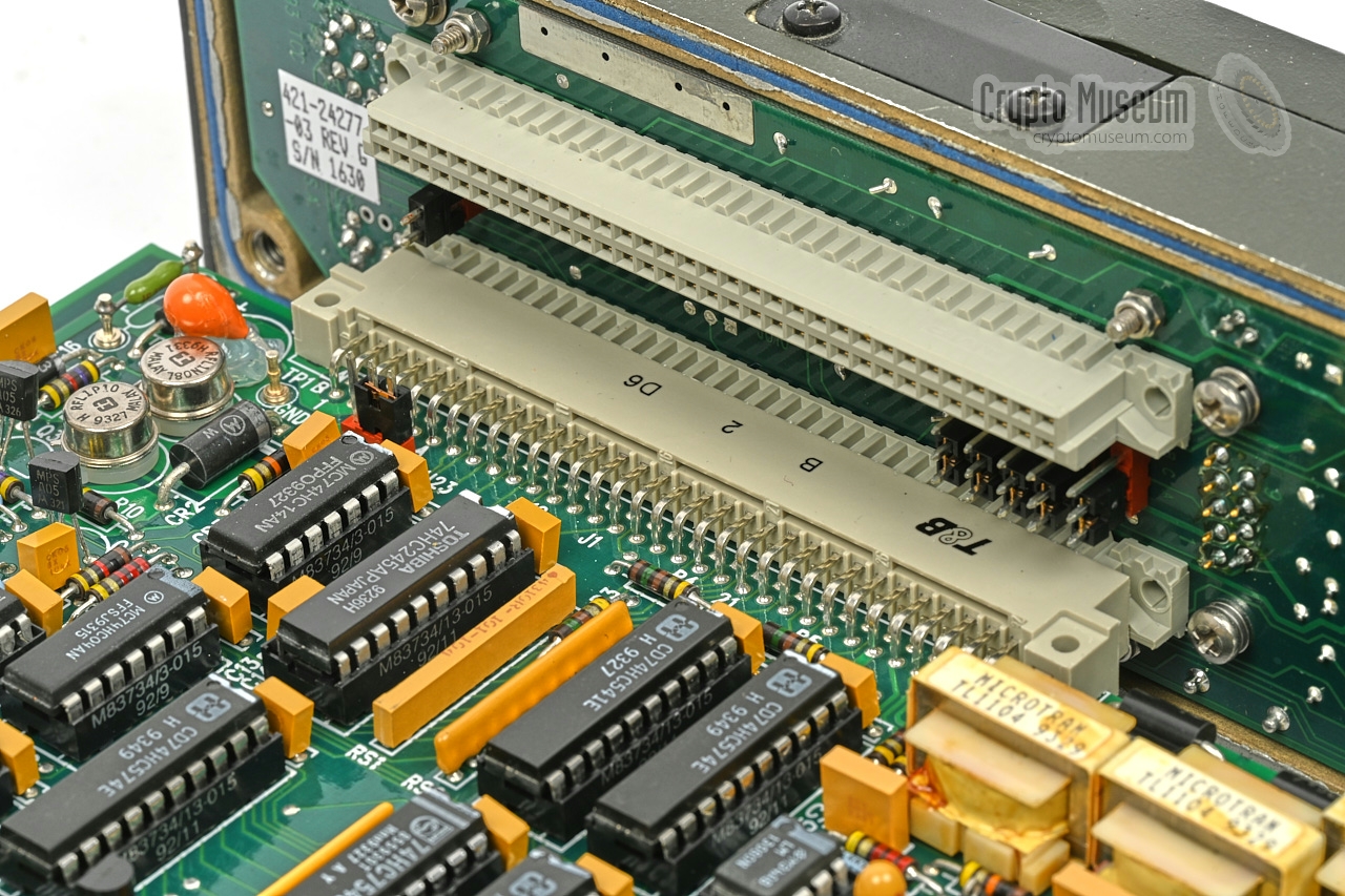
The board is built around a Motorola DSP56001 digital signal processor (DSP)
with 8KB of static RAM (SRAM) and firmware in three EPROMs. In addition
there is a custom chip made by Actel, which is actually a one-time programmable
(OTP) Field Programmable Gate Array (FPGA). The unit is controlled by a
Z80 microprocessor with 32KB SRAM and firmware in a single
EPROM. As timing is critical, a highly accurate 4 MHz temperature
compensated crystal oscillator (TCXO) is present.
The cryptographic keys for the internal key generator, and several other
parameters are kept in SRAM memory and are retained by a lithium battery
that is located at one of the corners of the board (the part with the yellow
label). Next to this backup battery is a so-called tamper switch,
which ensures that the keys are purged as soon as the case is opened.
|
At present we are unable to test this device as we have insufficient information
about the connections at the front panel. Furthermore, we do not know
whether or not a second PCB is required in the upper
slot of the front panel PCB.
Any further information would be appreciated.
|
1991 First development of DSP-9000 1993 Introduction of DSP-9000 line 2007 Embedded in radio equipment for Afgan forces 2009 $10 million order for Afgan forces 2013 Order for DSP-9000 equipment for Afgan forces
|
|
The DSP-9000 has a standard 6-pin socket, located at the top left of the
front panel, for connection of a handset or headset. It is wired to the
American U-229 standard.
|
- GND
- Speaker
- PTT
- Microphone
- Unused
- ?
|
|
|
At the left of the front panel (or at the centre of the rear)) is a 19-pin
receptacle for connection of the radio equipment. It carries the wiring for
the red interface (unencrypted) and for the black interface
(encrypted),
plus wiring for the connection of a remote control unit (RC). 1
The table below shows the pinout of this receptacle. Note that there are
four pairs of twisted wires for the balanced in- and outputs. Each pair has
a coloured wire (...H...) and a white wire (...L...). In case of a single-ended connection,
the white wire of each pair (...L...) should be connected to ground.
The shield of the interconnection cable (white/black wire) should also be
connected to ground.
|
| Pin | Name | Description | Colour |
A.
B. | SHI
SLI | Speaker H (in)
Speaker L (in) | green
white |
|
|
| C. | C/P | Select Cipher/Plain | grey |
|
|
D.
E. | MHI
MLI | Microphone H (in)
Microphone L (in) | red
white |
|
|
| F. | SELCAL | Selective call (out) | violet |
|
|
G.
H. | SHO
SLO | Speaker H (out)
Speaker L (out) | blue
white |
|
|
| J. | DPI | Data PTT (in) - option | green |
|
|
K.
L. | MHO
MLO | Microphone H (out)
Microphone L (out) | yellow
white |
|
|
| M. | SYNC | Remote sync init (in) | yellow |
|
|
| N. | PWR | Power +9 to +32V (in) | orange 2 |
|
|
| P. | PO | PTT (out) | red |
|
|
| R. | GND | Ground | brown 2 |
|
|
| S. | spare | unused | blue |
|
|
| T. | PI | PTT (in) | white |
|
|
| U. | V/D | Voice/Data | brown |
|
|
| V. | GND | Ground | black 2 |
|

|
-
The DSP-9000-RC came with a pre-wired break-out cable of which the
table shows the wire colours.
-
= Thicker wire
|
|
To the left of the display, behind the hinged keyboard, is a 9-pin female
DE-9S receptacle for connection of a
proprietary smart module or a special purpose key loading device.
The wiring of this connector is currently unknown.
|
Device Voice scrambler Purpose Voice privacy for two-way radio Principle Enhanced Domain Transform (EDT) Model DSP-9000 Manufacturer TCC Country USA Years 1991 - 2024+ Users Argentina, Austria, Afganistan Response 200 - 2800 Hz (400 to 2500 Hz minimum) Key types Local key, Network key, System key, Initialization Vector (IV) Key space 1.54 1099 (~ 329 bits) Including IV 1.01 10104 (~ 346 bits) Key storage Two EEPROM banks of 400 keys each FILL Smart Module 2K-W Reference TCXO crystal oscillator Data 1200 baud Sync In-band frequency shift keying (FSK) 74-bit sync burst Power 9 to 32V DC Consumption 1W (half-duplex), 2W (full-duplex) Temperature -20°C to +60°C Storage -40°C to +85°C Dimensions ? Weight ?
|
Device Key storage/transfer device Purpose Transfer keys to/from another DSP-9000 Name BAC Smart Module 2K-W Designator 401-24265-03 Rev. A HSN code 85437090000
|
Local keys EEPROM Network key EEPROM System key EPROM IV Generated automatically at each PTT-press
|
|
|
Enhanced Domain Transform
EDT
|
|
|
- Cryptographically controlled
- Three distinct DSP-based audio manipulations
- Retains 3 kHz bandwidth
|
HSE-6000 Secure radio handset CSD-3324 Secure telephone
|
415-26533-01 DSP-9000 RB 20 foot radio cable with power leg 415-24420 DSP-9000 RC interface cable 411-26534 DSP-9000 RB radio cable connector 401-24259-06 DSP-9000 RB/RC military voice encryptor 401-25470 DSP-9000 HS ruggedised handset encryptor 401-26531 DSP-9000 PWS AC/DC 12V/DC 401-24422-02 DSP-9000 dual rack mount RC assembly 17" 401-24390-01 DSP-9000 RC trunk mount 401-26010-23 HSE-6000 seal voice encryptor w/o mic bias 401-26458-02 Helmet interface caable set hi-gain EU, NATO 415-26449-01 HSE intercom (ICS) cable 415-26052 HSE to Smart Module cable 411-26013 HSE-6000 removable battery 545-26227(-01) HSE-6000 vest mount pouch 401-24265-03 Smart Module 2K-W key fill device 545-25486 HSE-6000/9000 EPROM burner 401-25593-04 HSE-6000/9000 crypto management system
|
- US Patent 3,610,828
Privacy Communication System
Alfred L. Girard for TCC. Filed 23 May 1967.
- US Patent 3,691,464
Asynchronous swept frequency communication system 1
David S. Dayton for TCC. Filed 25 November 1968.
- US Patent 3,723,878
Voice Privacy Device
Charles K. Miller for TCC. Filed 30 July 1970.
- US Patent 4,195,202
Voice privacy system with amplitude masking
Arnold M. McCalmont for TCC. Filed 3 January 1978.
- US Patent 4,276,652
Secure communication system with improved frequency-hopping arrangement
Arnold M. McCalmont for TCC. Filed 2 October 1978.
- US Patent 4,392,021
Secure facsimile transmission system using time-delay modulation
Matthew W. Slate for TCC. Filed 28 July 1980.
- US Patent 4,433,211
Privacy communication system employing time/frequency transformation
Arnold M. McCalmont for TCC. Filed 4 November 1981.
|
-
On the rear of the device,
this patent is listed as 3,691,414
but this is probably a misprint as it refers to a Siemens patent for
a stepper motor.
|
|
|
|
Any links shown in red are currently unavailable.
If you like the information on this website, why not make a donation?
© Crypto Museum. Created: Thursday 04 August 2022. Last changed: Tuesday, 06 January 2026 - 09:28 CET.
|
 |

|
|
|
| | |