|
|
|
|
|

|
|
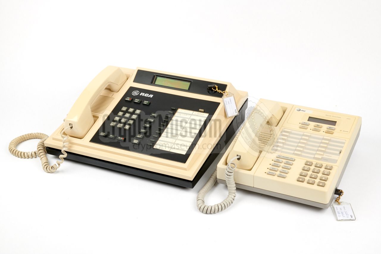
RCA USA Phone STU-III
The RCA STU-III resembles a regular telephone set, but is about
twice the size of a competing desktop set,
making it the largest STU-III set on the market.
It measures approx. 343 x 310 x 135 mm
and weighs 7264 grams (without PSU).
The device is an
NSA Type 1 encryption product,
which makes it suitable for the US Government
for traffic up to the level of TOP SECRET.
Speech is digitized with an LPC-10E or CELP vocoder,
encrypted with a secret NSA algorithm similar to
SAVILLE, and sent through a regular POTS/PSTN
analogue telephone line at 2400 or 4800 baud.
|
|
|
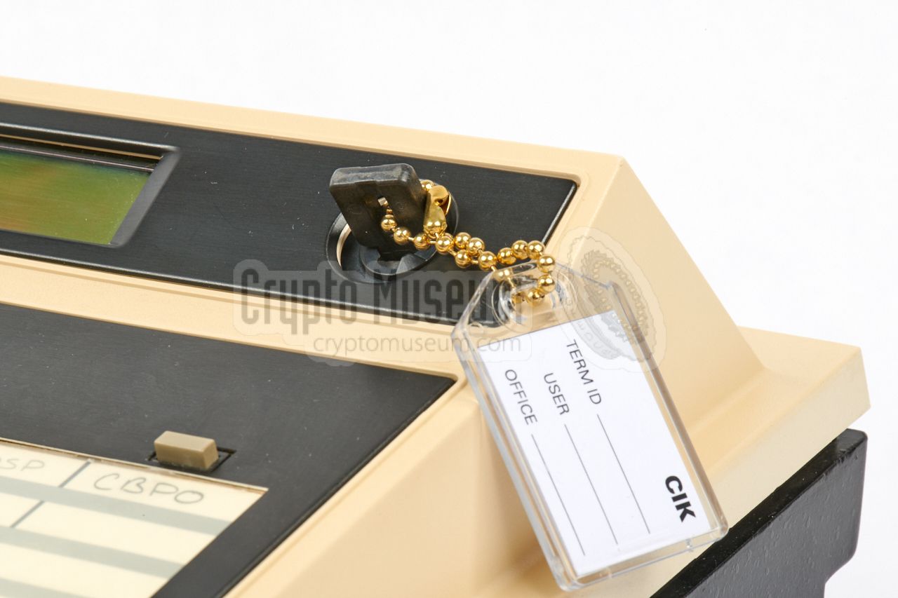
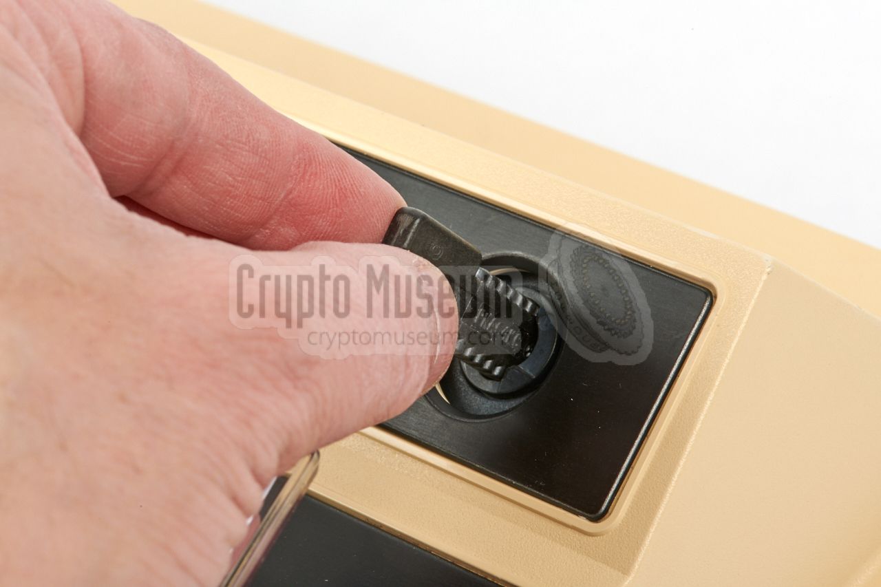
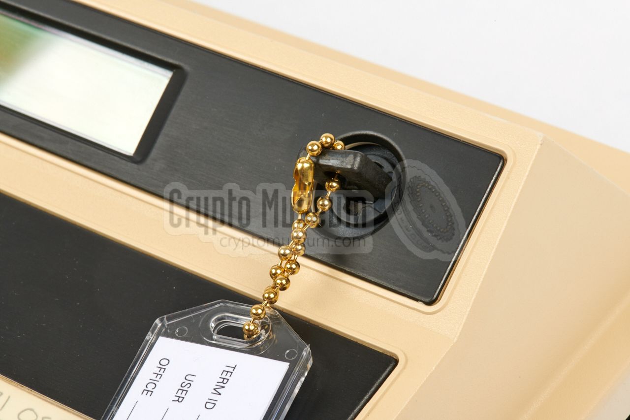
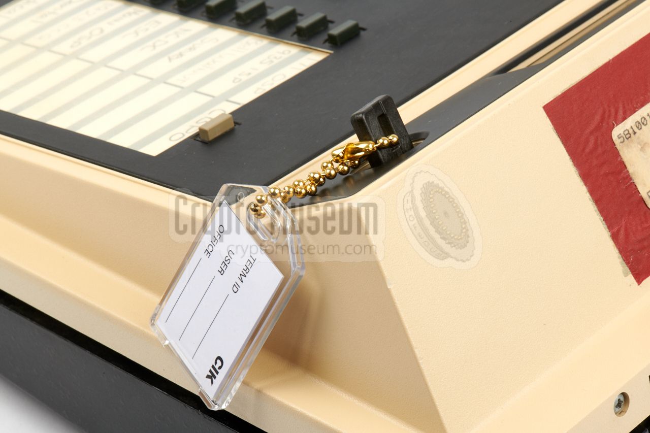
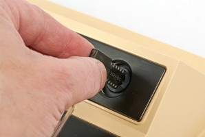
At the top right is a socket, or receptacle, for a
KSD-64A key
that is used as the Crypto Ignition Key (CIK). It has to be
inserted and then turned 90° clockwise, before encrypted calls
are possible. Once the keys are loaded, the CIK is paired
with the terminal. Without the matching CIK, the keys inside
the terminal have no meaning. Likewise, the CIK has no meaning
when used with another STU-III terminal. In 2005, the GE/RCA STU-III
was available for the modest price of USD 2200 [3].
When development of the STU-III was started in 1986, RCA was in the
process of being taken over by
General Electric (GE).
The unit shown above
was made in 1990 and carries
both the RCA and the GE logo.
A new – smaller – model was later introduced under the GE brand.
The GE/RCA STU-III was phased out over the course of 2009,
along with all other STU-III terminals,
with the last keys expiring on 31 December 2009.
It was succeeded by the
Secure Terminal Equipment (STE).
|
 |
-
RCA was later taken over by
General Electric
(GE), who kept selling the device under the
RCA
brandname, probably because of the international
approval status of the device. The responsible GE
business unit was later sold to Lockheed Martin, and
eventually spun-off as
L-3 Communications East.
|
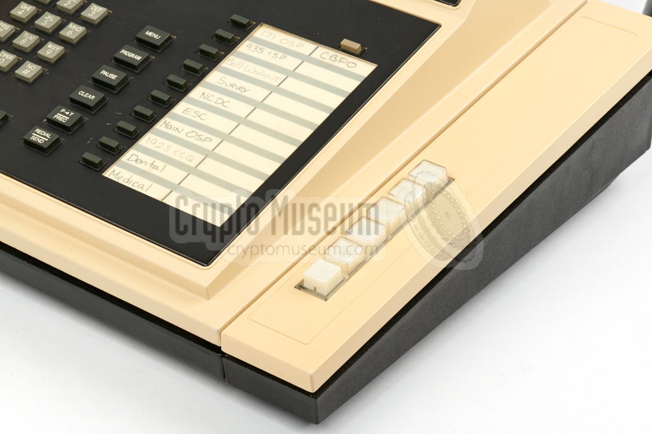
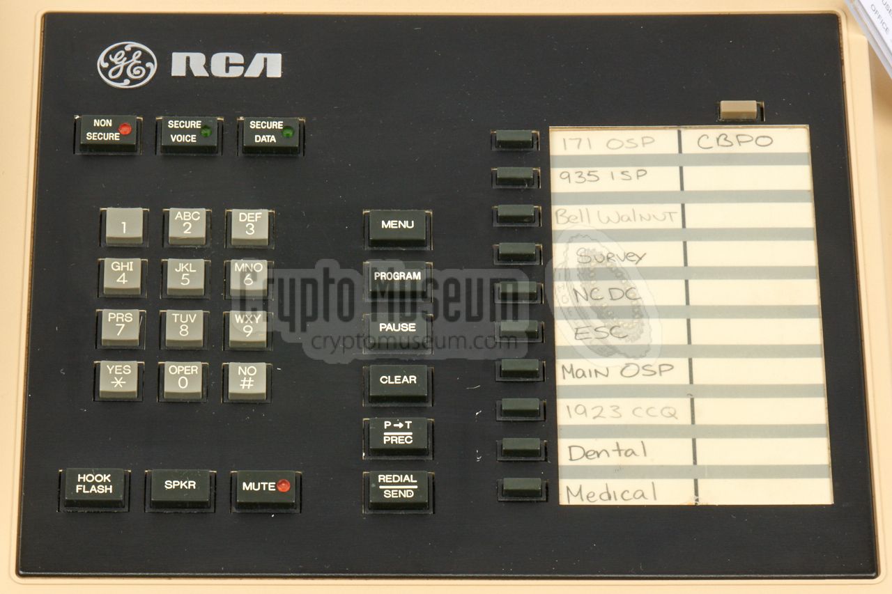
The diagram below gives a quick overview of the controls and
features of the GE/RCA STU-III terminal. At the left is a regular
handset, which is connected to the RJ-10 socket at the left side.
Below the handset is a speaker for handsfree operation. At the
centre is a regular keypad with numbers (0-9) and the
* and # buttons.
Above the keypad are three buttons for selection of the desired
MODE of operation.
At the right are two memory banks for 10 direct-dial numbers each.
At the upper edge is the Liquid Crystal Display (LCD) for interaction
with the user. At the top right is a receptacle for a
physical black plastic KSD-64A key,
which has a built-in 64Kb EEPROM.
The key can be used for several applications, but its most common use
is as Crypto Ignition Key (CIK).
All connections of the device are at the rear, as show in the
diagram above. At the right is the DC INPUT socket for connection
of the external power supply unit (PSU).
To its left is an RJ-11 socket for connection to a regular 2-wire
analogue public switched telephone network (PSTN), plus an RJ-11
socket for connection to a 4-wire military AUTOVON network.
At the far left is a 25-pin female D-type socket with a V.24
data interface, also known as an RS-232 interface or serial port.
|
|
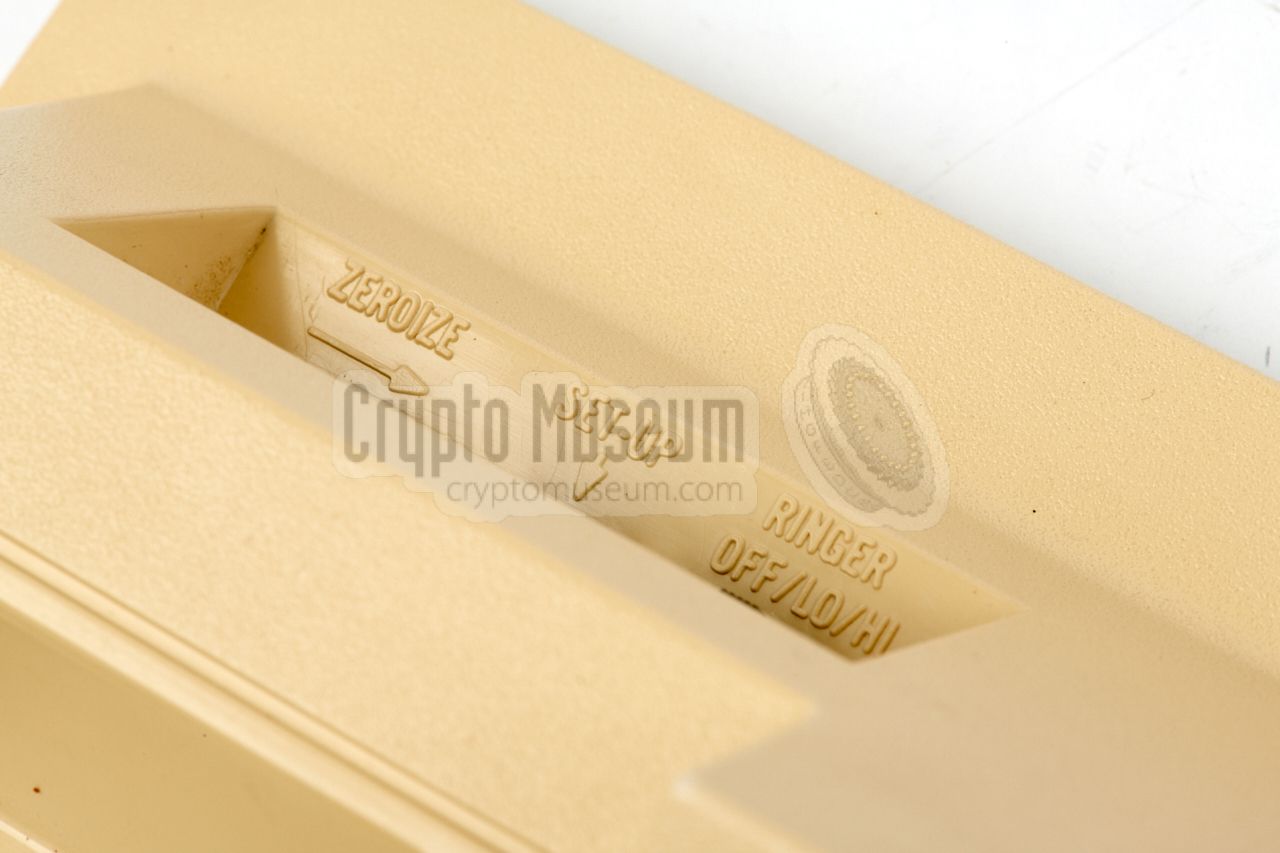
As with all high-end encryption products used by the goverment and
the department of defense, the device can be ZEROIZED in case of
an emergency. For this purpose, a
momentary slide switch is present
at the far left of the rear side, just behind the handset.
Pushing this switch to the right (i.e. away from the side), purges
all cryptographic keys. This can be done with or without the CIK
installed. Once ZEROIZED, it can no longer be used for
secure traffic, until new keys are loaded.
|
|
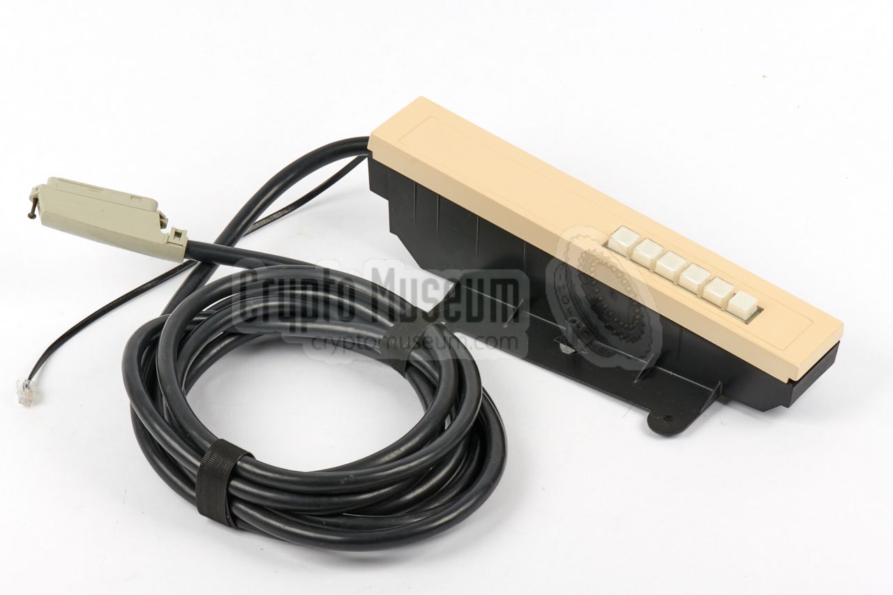
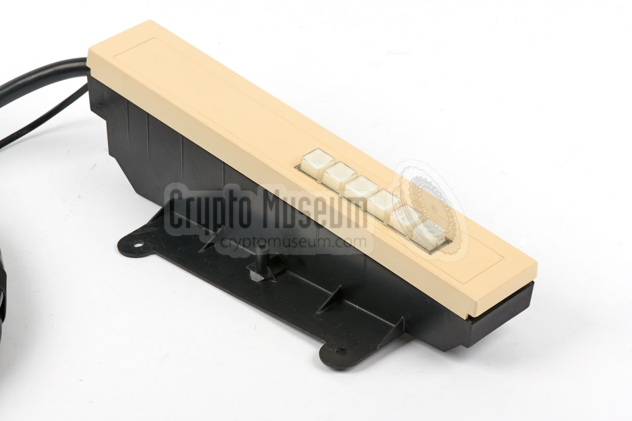
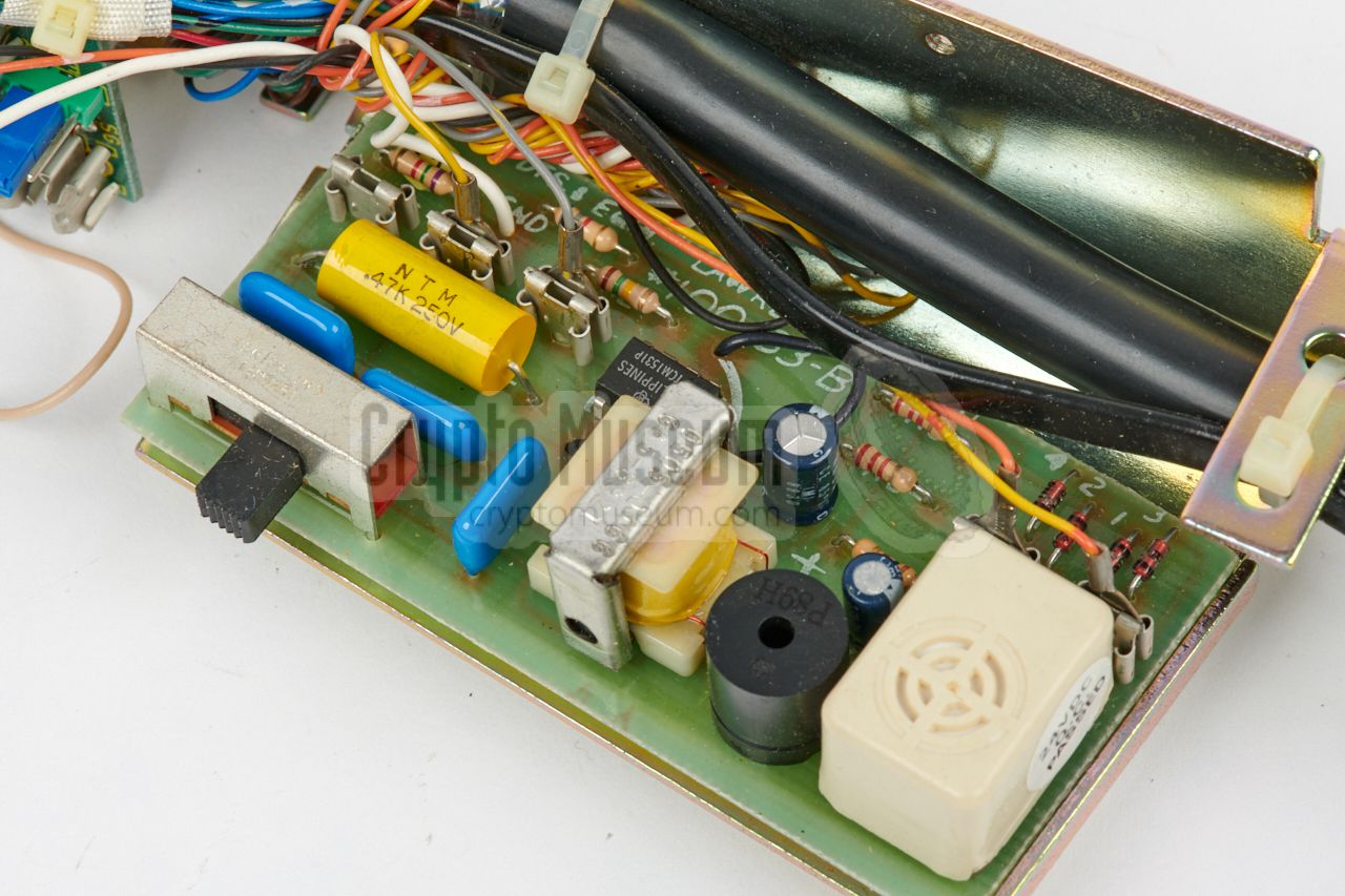
The RCA/STU-III could optionally be expanded with the so-called
multi-line adapter
shown in the image below, which allows
up to five external regular analogue PSTN lines to be accessed.
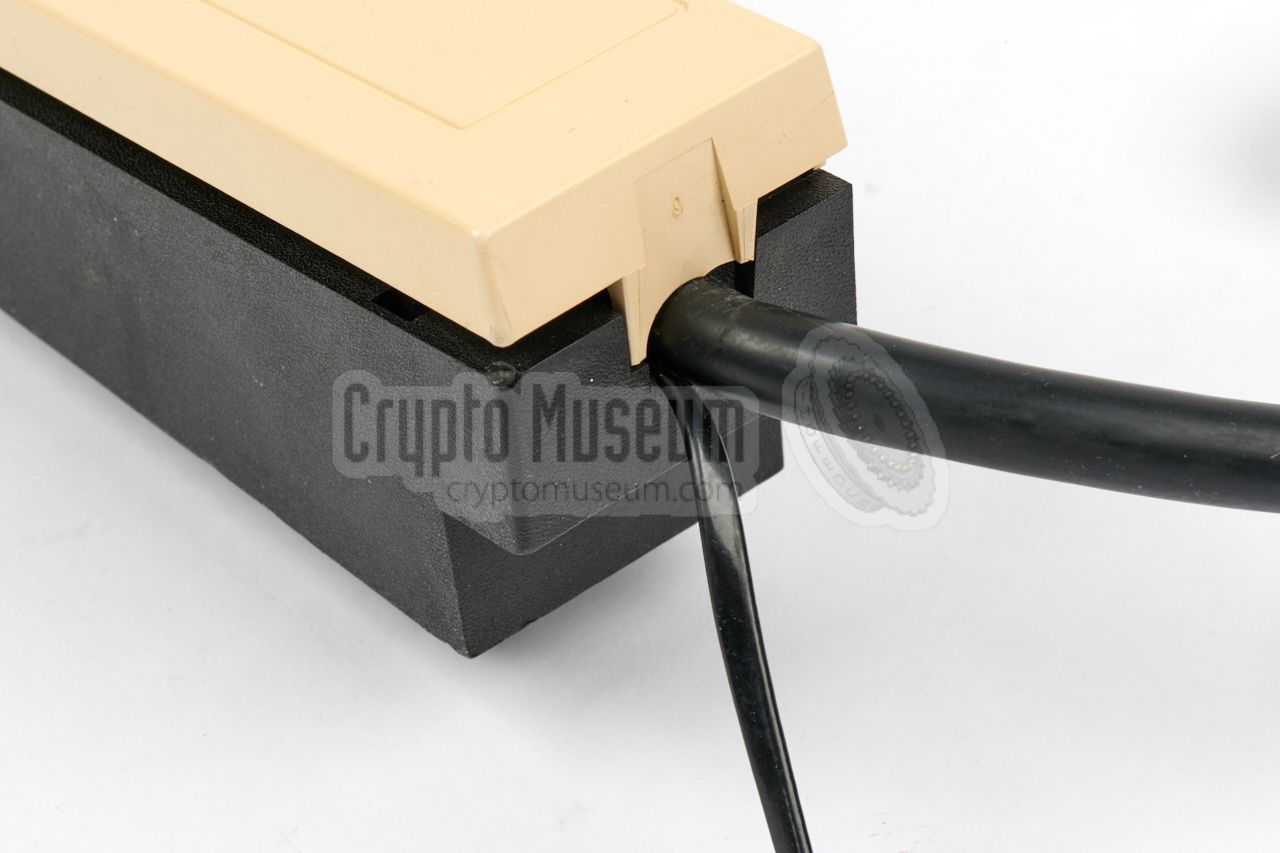
It has a bracket at its left side,
which allows it to be affixed
to the right side of the RCA/STU-III terminal.
|
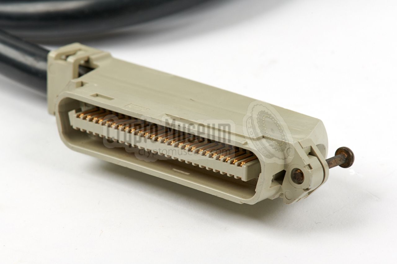
It has a thin wire that is
connected to the PSTN socket of the terminal,
and a thick cable with a standard
wide multi-line connector
that should be connected to the telephone wall socket. 1
By default, the STU-III is disconnected from the line, and a
ringer circuit inside the adapter
will signal an incoming
call. At the same time, a lamp (inside the push-button) will indicate
which line is ringing. By pressing the corresponding push-button,
the STU-III is connected to that line, after which the handset
should be lifted from the cradle to answer the incoming call.
|
|
|
|
Once the call has ended, the handset is placed in the cradle again
so that the line is disconnected. The frontmost button on the
multi-line adapter is then pressed to reset the device to its default
state. For outgoing calls, the user selects the desired line,
lifts the handset and dials the number.
|
A STU-III phone can be connected to any standard analog telephone line
(POTS).
A call is always initiated in non-secure mode. In order to
go secure, both parties have to insert and activate their unique
Crypto Ignition Key (CIK), after which
one of the parties initiates
the secure conversation by pressing the SECURE VOICE button.
After a delay of 15 seconds, during which the internal modems are synchronised
and the CODEC and KEYs are negotiated, secure traffic is possible.
The 10 to 15 second delay is typical for
all STU-III phones
and was considered a nuisance to the user. Furthermore, valuable intelligence
is often given away in the clear voice conversation that takes place
before secure mode is entered.
The 10 second delay did not occur with the later
STE.
Until today, there have been no reports of STU-III units being broken.
That does not mean, however, that foreign intelligence services did not
gather valuable information from intercepted lines, directly before
and after the secure part of the conversation.
|
|
-
Note that there is also a thin ground wire
at the bottom, that should be connected to a screw at the bottom of the
STU-III terminal.
|
|
|
Key storage device
KSD-64A
|
|
|
|
All key material is usually generated by an external EKMS
and loaded into
the STU-III by means of a so-called Key Storage Device (KSD),
such as the KSD-64A
or the later PK-64KC,
manufactured by Datakey Inc. (USA).
The KSD looks like a plastic toy key, and acts like the ignition key of a car.
|
The KSD is entered into a so-called keyceptacle at the
top right of the RCA/STU-III unit, to the right of the display. Once inserted,
it should be rotated 90° clockwise, in order to unlock the
secure features of the phone.
The KSD can be used for a variety of purposes,
such as: Crypto Ignition Key (CIK), Master CIK, FILL Key (FK),
Terminal Activation Key (TAK), Security Activation Key (SAC)
and Traffic Encryption Key (TEK).
➤ More about the KSD-64
|
|
|
|
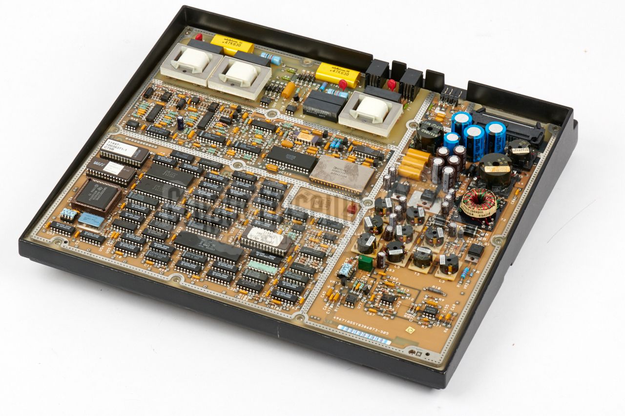
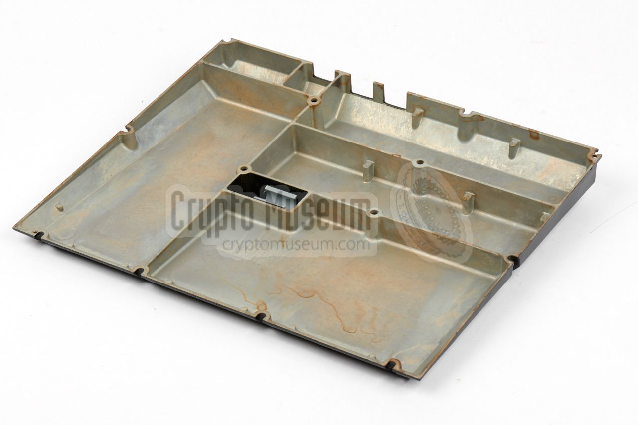
The GE/RCA STU-III is housed in a heavy die-cast aluminium
enclosure, with several internal die-cast aluminium shieldings,
and a plastic top case shell that holds the controls. The control
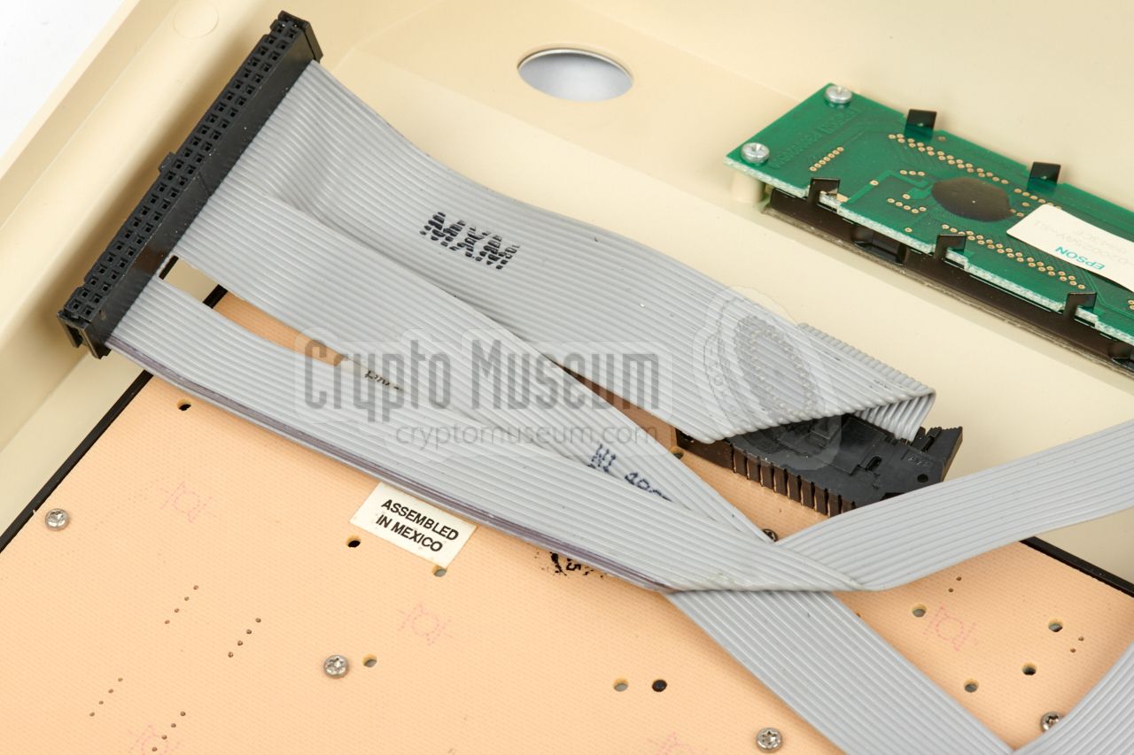
panel can be removed by releasing three small screws
at the rear
and disconnecting a 50-way header.
|
The control panel of the device is the only part that is not
TEMPEST shielded. In fact, it is not shielded at all. Although
the wiring between the control panel and the main unit is
extremely well filtered, the radiation from the control panel
itself might be exploitable by a malicious party.
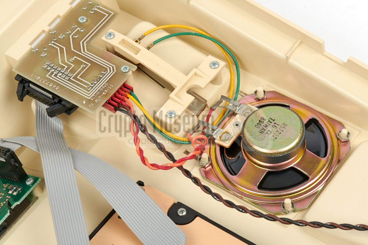
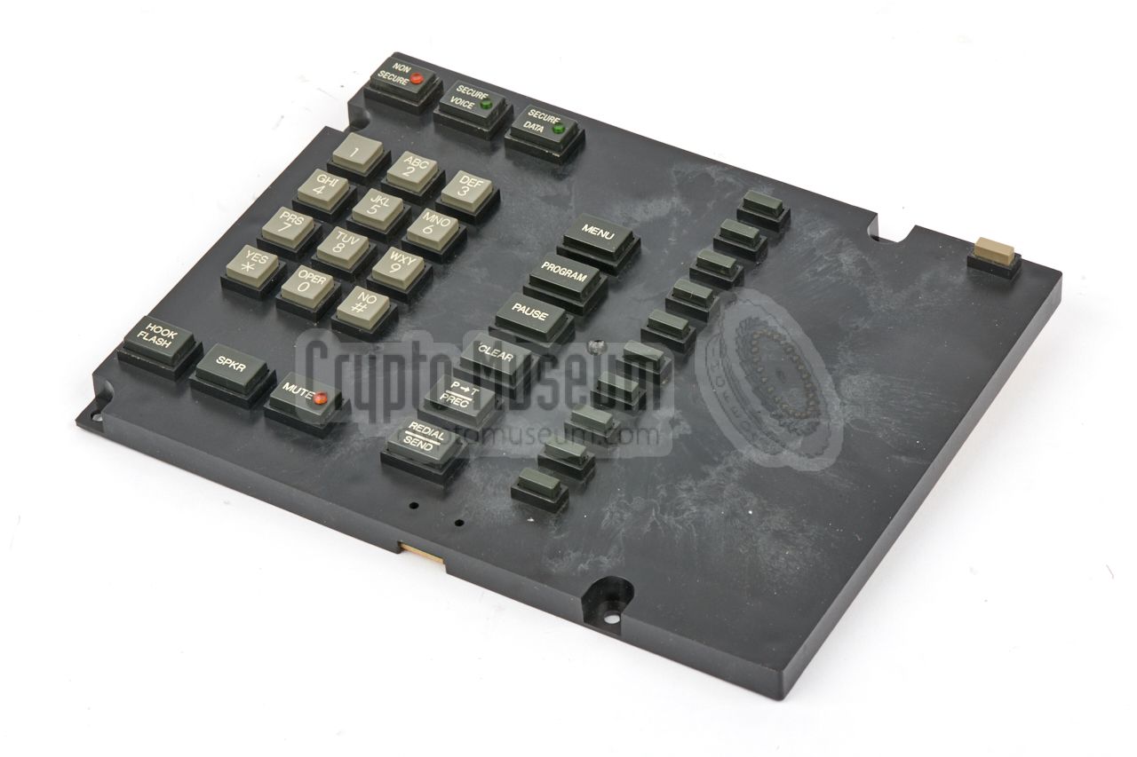
The image on the right shows the inside of the control panel.
At the bottom left is the
pre-assembled keypad. At the top is
the EPSON LCD display.
At the right is the speaker and – towards the rear – the
hook switch and a small PCB
with extra controls that are
accessible from the rear.
|
|
|
|
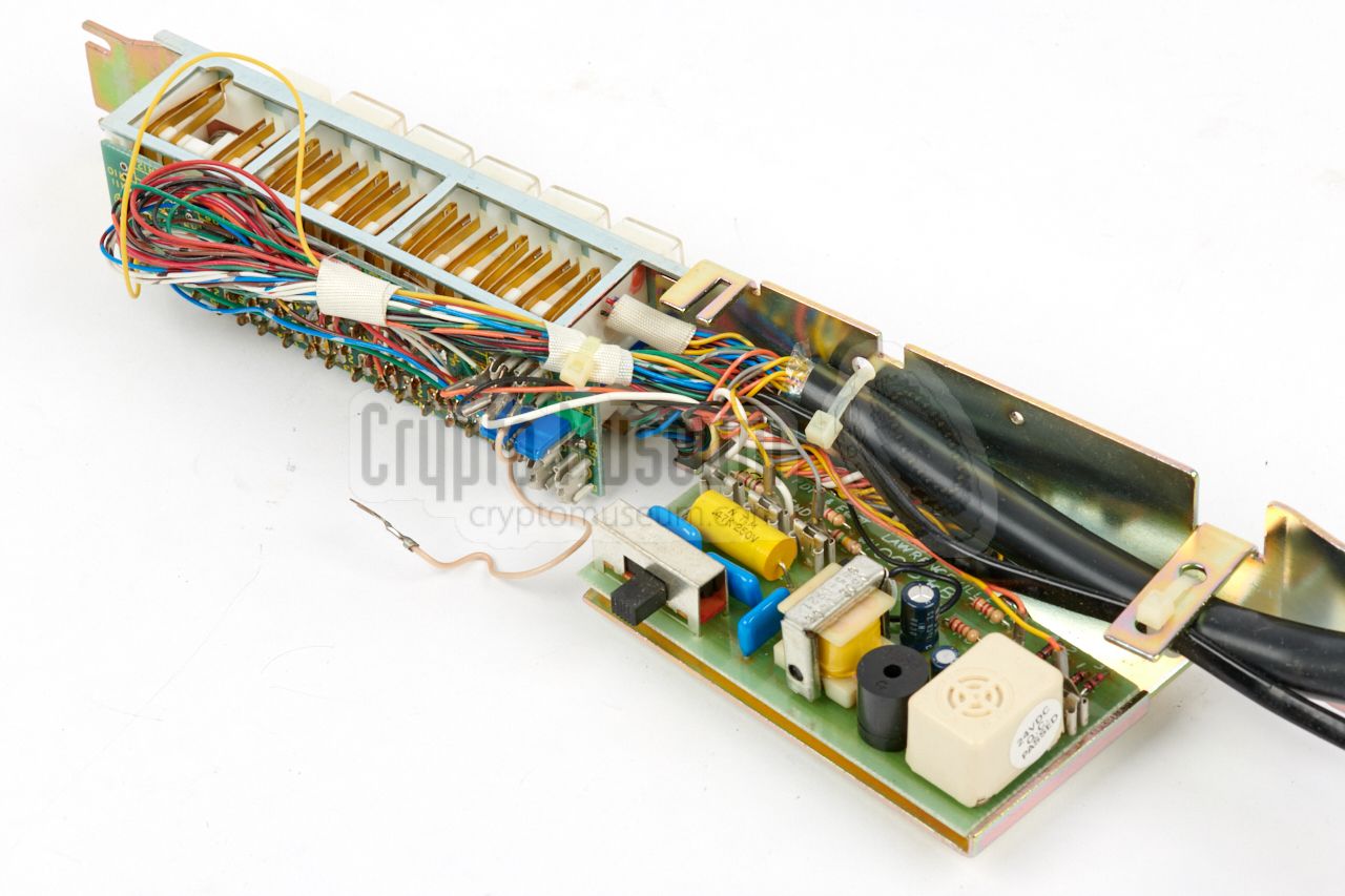
The large black 50-way connector at the left, connects the control
panel to the main unit. The remainder of the set consists of a
die-cast aluminium chassis, with two large PCBs: one fitted at the
top and one fitted at the bottom, each TEMPEST shielded by an
aluminium die-cast shell.
|
|
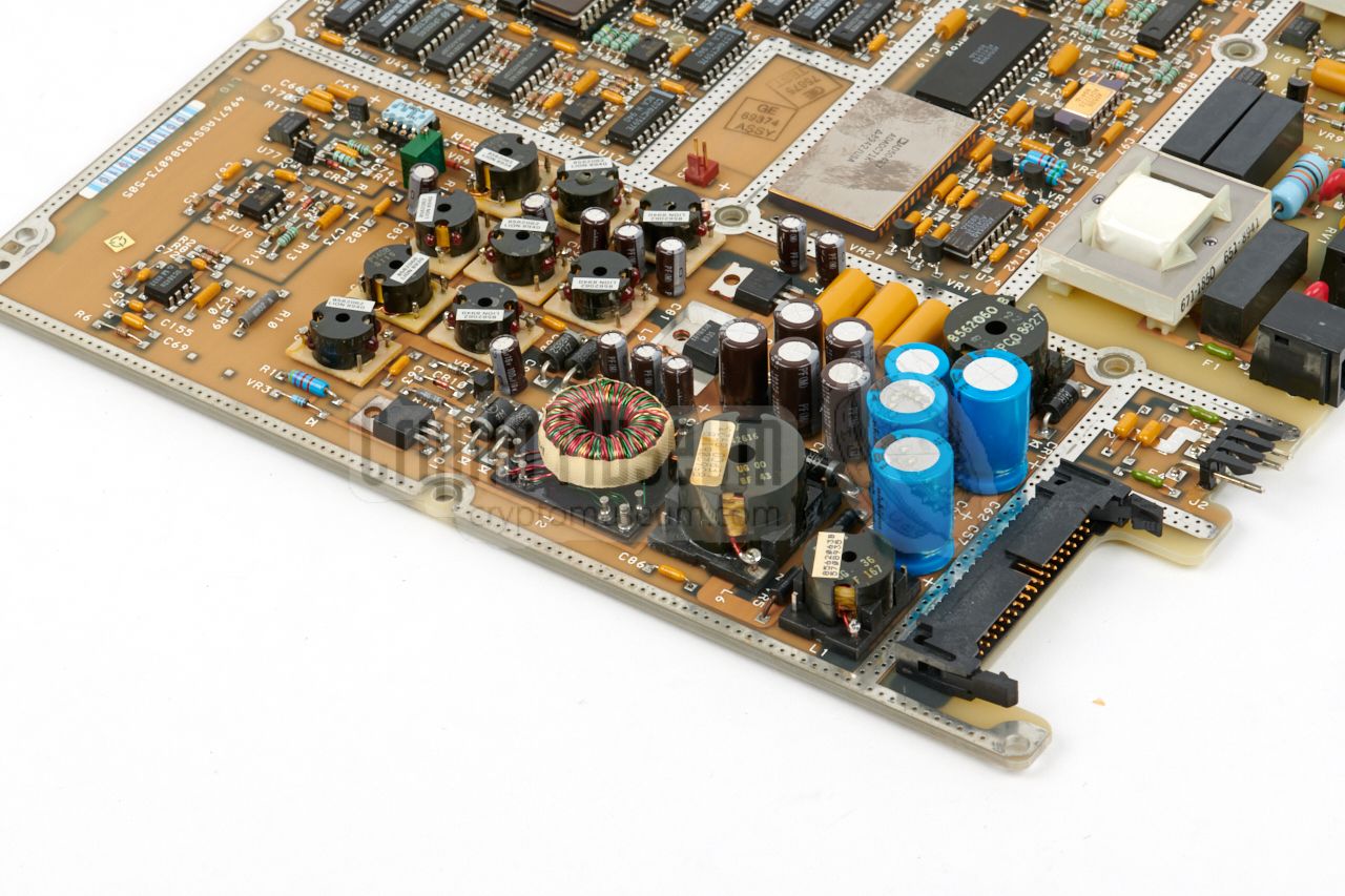
Note that this part of the device does not handle the actual
encryption. It only handles the speech circuits and provides
the necessary voltages for the rest of the device. The board has a
large 34-way header at the rear right corner, by which it is
connected to the main board at the other side.
|
|
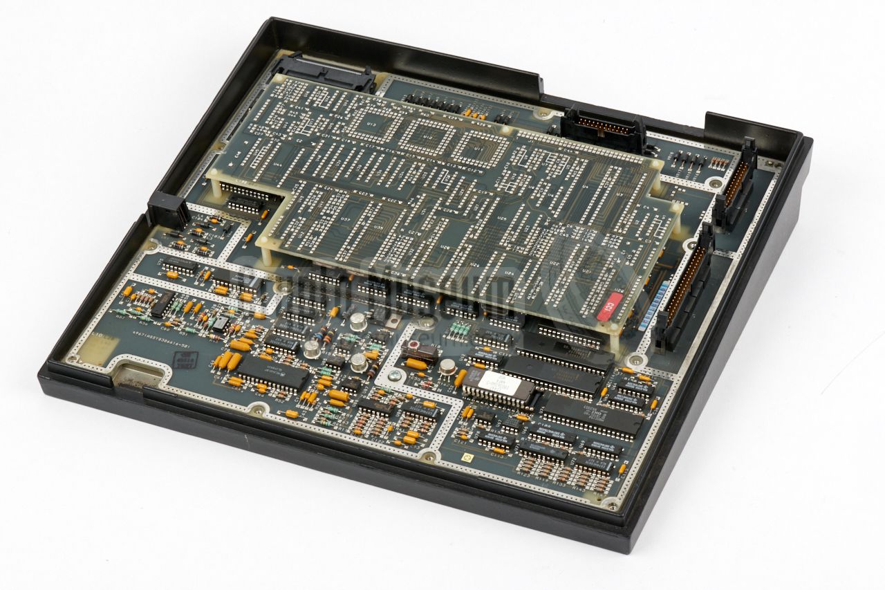
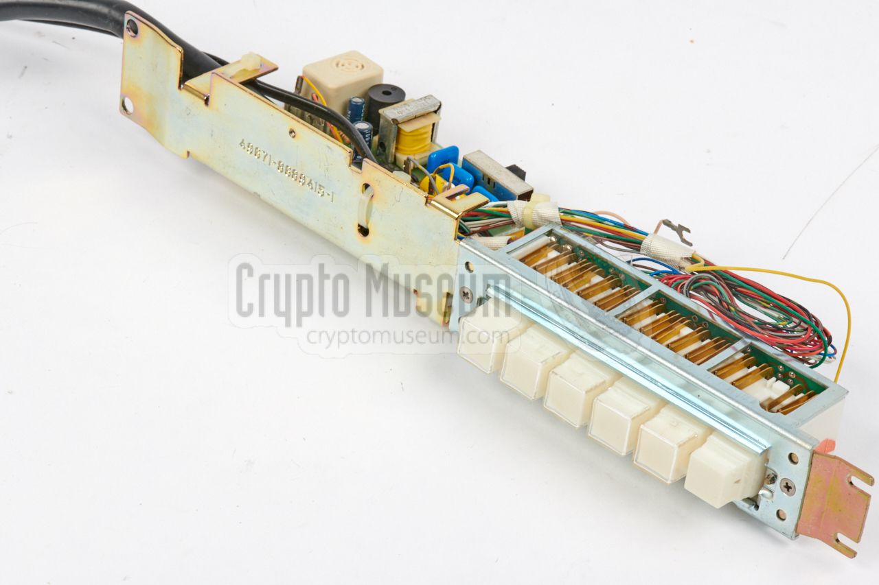
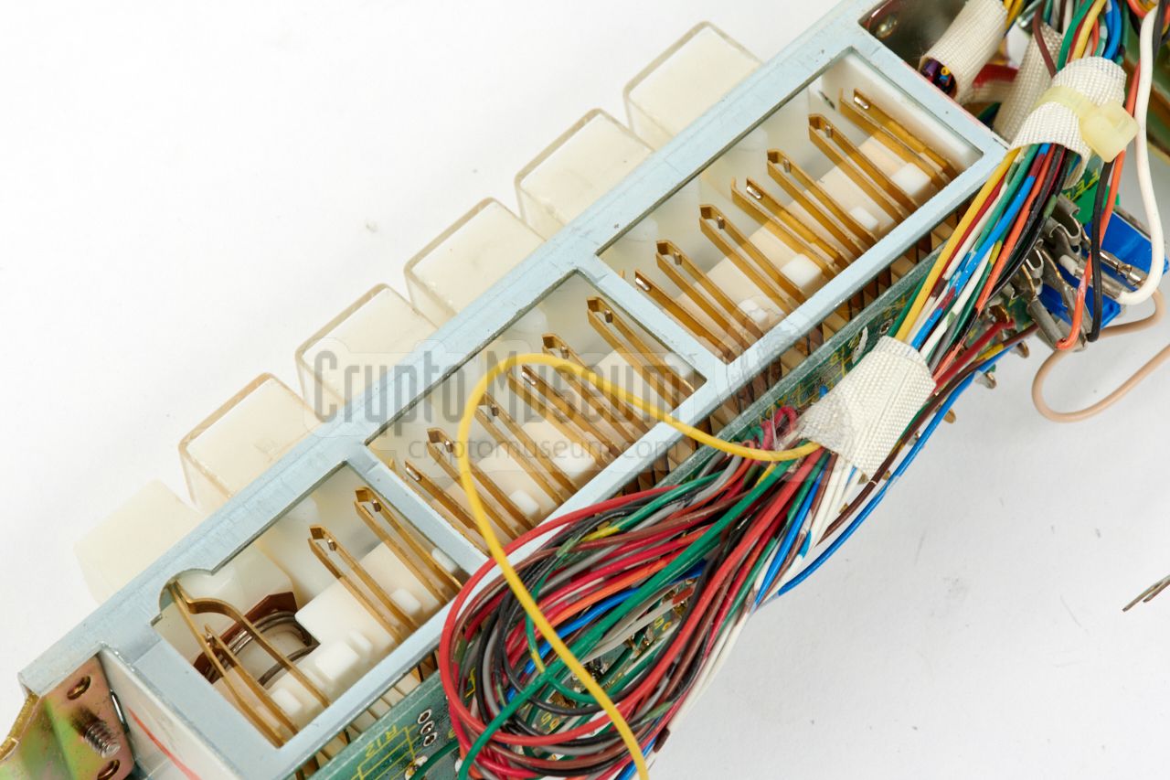
The key receptacle is connected to the main board by means of a
30-way ribbon cable header that should be disconnected. After removing the
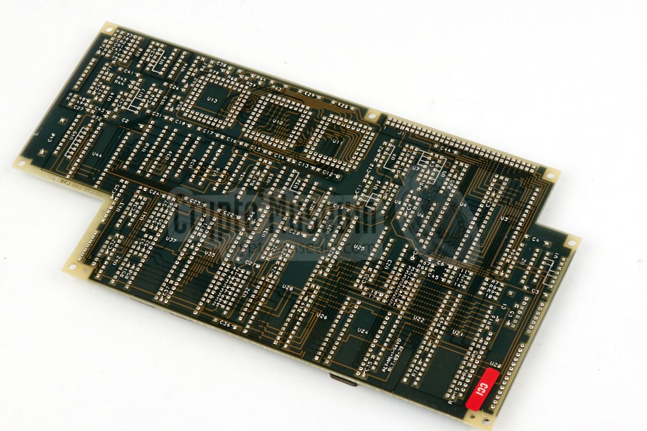
shield, the main board becomes visible, as shown in the image above.
It consists of a large PCB,
with a smaller daughter card fitted on top.
|
The larger PCB is the
main board that holds various microcontrollers.
It is connected to the
telephone board at the bottom side of the chassis,
by means of a 34-way ribbon cable in the rear left corner. This cable
carries the necessary voltages for the digital circuits, plus the digital
lines to the telephone interface.
The main board also holds a TI TMS320 DSP,
similar to the one on the telephone board,
which is probably used as the other half of the LPC-10 CODEC. One half is
usually the speech analyser, whilst the other half forms a speech synthesizer.
|
|
|
|
The rest of the board holds a microcontroller for handling the user
interface (i.e. the display and the keypad), and two further microcontrollers
for handling the input/output data streams. It also holds a V.24
synchronous/asynchronous serial RS232 port, which is available
at the rear (DATA).
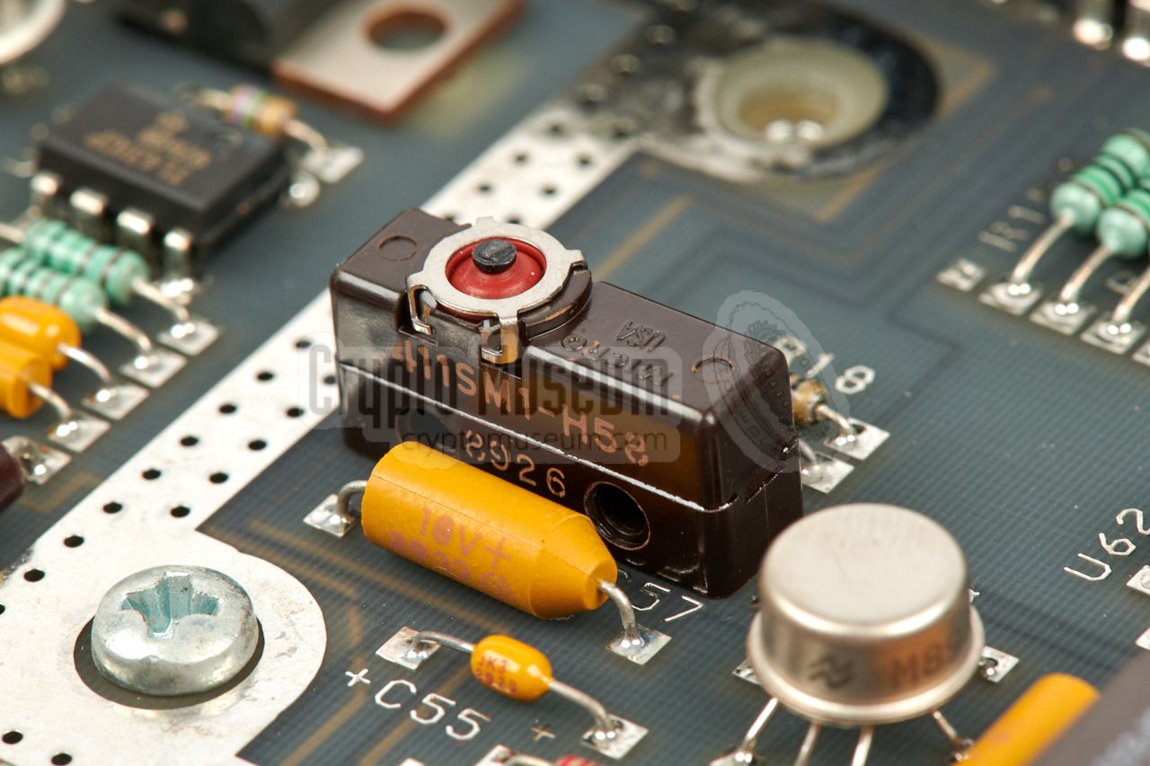
At the centre of the board is a so-called
TAMPER-switch that is activated
by a spring inside the die-cast shell.
It ensures that the cryptographic
keys are purged when the unit is disassembled. 2
|
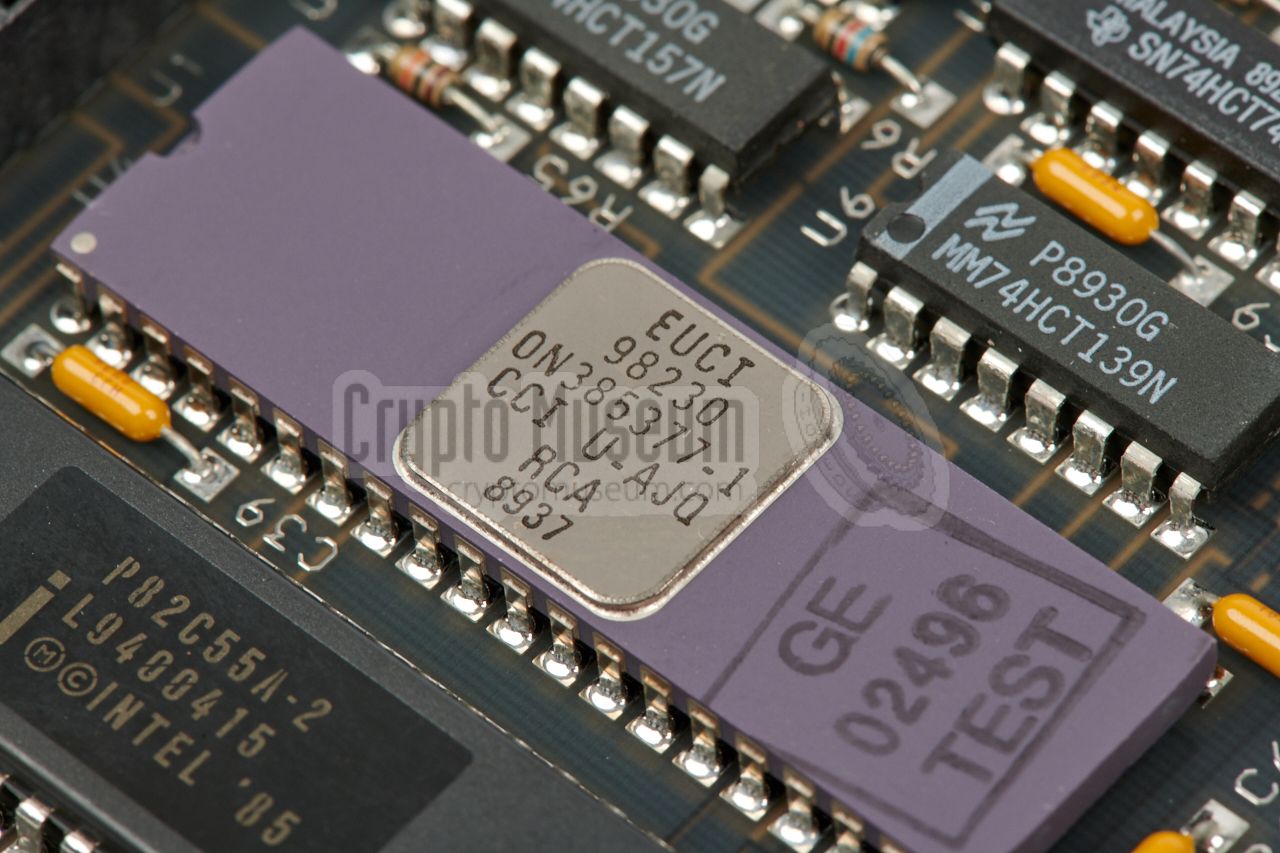
The actual encryption and decryption is handled by a
separate PCB
that is fitted as a smaller card
on top of the main board.
It is the secret part of the phone, and carries a red CCI label
to indicate that this part is a controlled cryptographic item.
The board carries various 8051 microcontrollers, several 16 x 16 bit
multipliers and CMOS RAM, and also holds the
secret NSA Type 1 encryption algorithm,
part of which is implemented in the
special custom chip
shown in the image on the right. The chip is marked as CCI and carries
a manufacturing date code of week 37 of 1989.
|
|
|
|
By implementing the cryptographic encoder/decoder as a separate daughter
card, it was possible to swap it for a less secure Type 2, Type 3 or Type 4
variant, so that the device could be sold to (controlled) customers
outside of the US Government. The device is extremely well-built,
and it is hard to imagine that it could be manufactured for an end-user
price of USD 2200, even in 1990.
|
-
It is also possible that the TMS320 DSP on the telephone board was used
for the implementation of the MODEM, and that the LPC-10
and CELP features were handled by
another TMS320 on the main board.
-
The TAMPER-switch basically cuts the power from the backup battery to
the CMOS RAM.
|
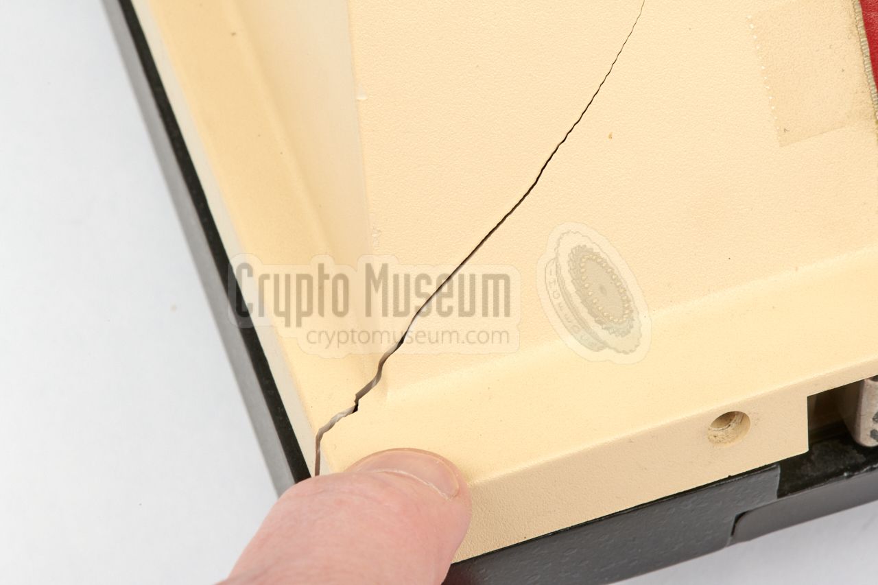
Although the item had been packed well, it got damaged in transit
when it was shipped to the Netherlands, probably due to improper
handling by the carrier. The large weight of the die-cast chassis
and case shells, had caused two serious cracks in the yellow plastic
control panel; one at the front corner,
and a larger one at the rear.
Both cracks were repaired by firmly pressing the parts together,
and then melting the plastic from the rear (i.e. the inside) with
a soldering iron at 150°C. After repeating this process a number of
times, the cracks are now practically invisible.
|
|
|
|
The front panel of the multi-line adapter also had a crack and two of its
mounting stubs were broken off. They were melted back in place with a
soldering iron and reinforced with a strong 2-component adhesive.
The crack was repaired with a soldering iron at 150°C, as described above.
|
|
At present, the original power supply unit for our RCA/STU-III is missing.
The connections shown below have been assumed (by studing the PCB layout),
but the voltages are currently unknown. Any help in this area will be
much appreciated. Below is the pinout when looking into the socket.
|
|
The GE/RCA STU-III is known under the following names and designators:
|
- RCA STU-III/LCT
- GE STU-III/LCT
- GE/RCA STU-III
- STU-III/LCT TYPE1/RCA-CCI-EC
- NSN 5810-01-230-1486
|
- Operational Guide for RCA/STU-III - WANTED
RCA, General Electric. ON416007-1.
|
|
|
|
Any links shown in red are currently unavailable.
If you like the information on this website, why not make a donation?
© Crypto Museum. Created: Saturday 10 February 2018. Last changed: Wednesday, 05 November 2025 - 11:53 CET.
|
|

|
|
|