|
|
|
|
|

|
|
Rotor OMI ← CR
Electromechanical cipher machine
- wanted item
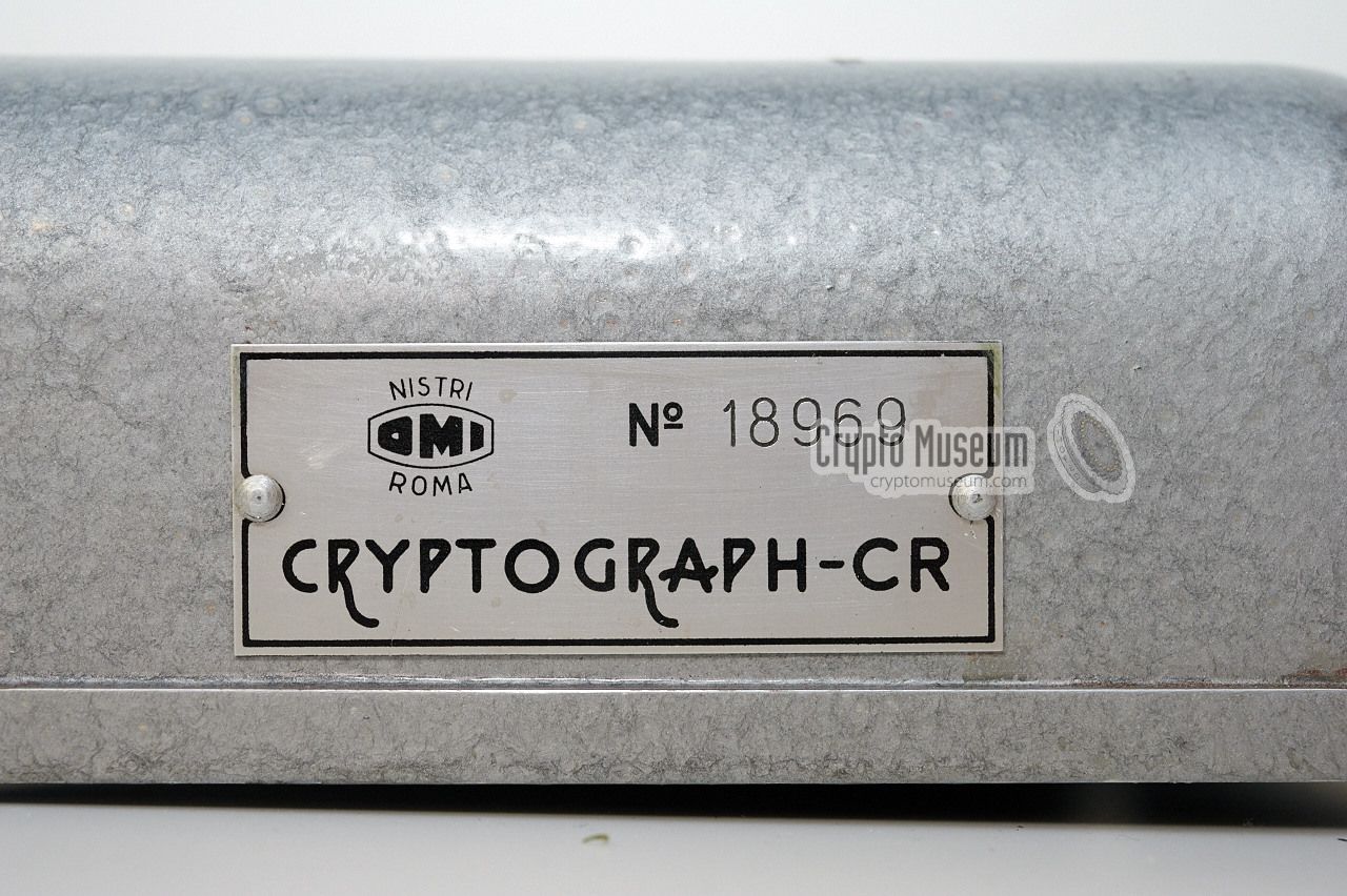
Cryptograph-CR Mark II, or CR-2, is an
electromechanical cipher machine, produced
by OMI in Rome
(Italy) in the early 1960s, as an upgraded version of the earlier
the OMI Cryptograph-CR
1 . It was intended for use by the
Italian Armed forces, in particular by the Italian Navy (MMI). 4
|
The machine was initially sold as a (green) Cryptograph-CR,
and was given a mid-life upgrade after several years of service.
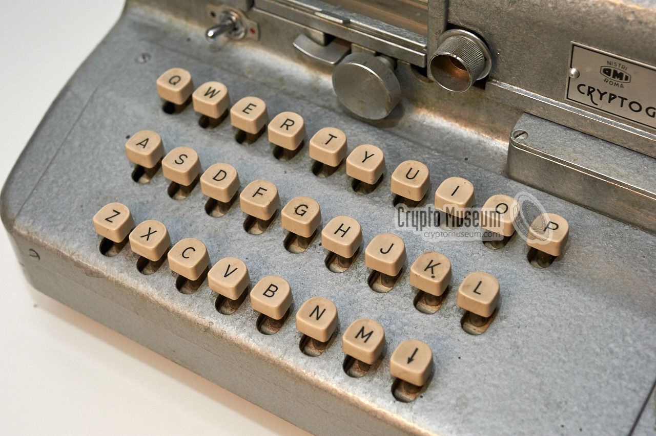
The original (partly)
mechanical keyboard was removed and
replaced by a fully electric one, of
which the keys are placed closer together. The spacebar was dropped and the
letter 'W' was added, so that the machine now supports the full A-Z alphabet.
The unused holes of the keyboard are covered by a new panel that is mounted
over it. At the same time, the case of the machine was repainted in grey
hammerite as shown here. 2
|
|
|
The two switches that enabled plaintext and ciphertext printing were
also dropped,
and their holes were covered. As a result, the machine now always prints both
plaintext and ciphertext. Inside the machine, parts of the
Power Supply Unit
(PSU) were modernised and
26 electric relays
were added, each of which is
connected to one of the switches on the keyboard. In order to accomodate these
relays, the paper supply drawer at the bottom right has been given up as well.
The machine is similar in operation to the
German Enigma, in that it
has a set of electromechanical cipher wheels with 26 contacts
at either side, an entry disc (called Eintrittzwalze or ETW on Enigma)
and a reflector (Umkehrwalze or UKW).
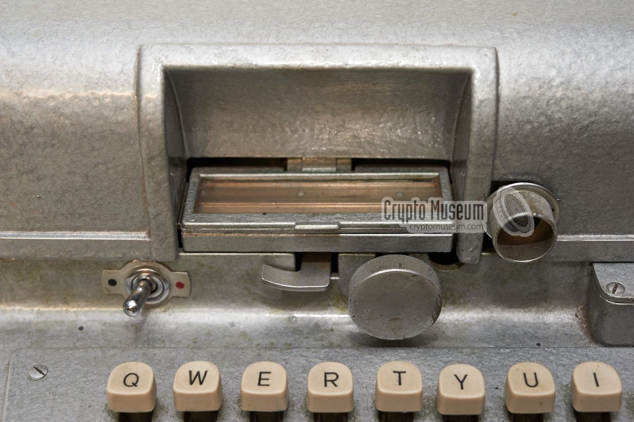
Unlike Enigma however, the OMI Cryptograph
has a built-in printer that produces the output
on two paper strips at the front of the machine, just behind the keyboard.
One strip shows the plaintext; the other one the ciphertext.
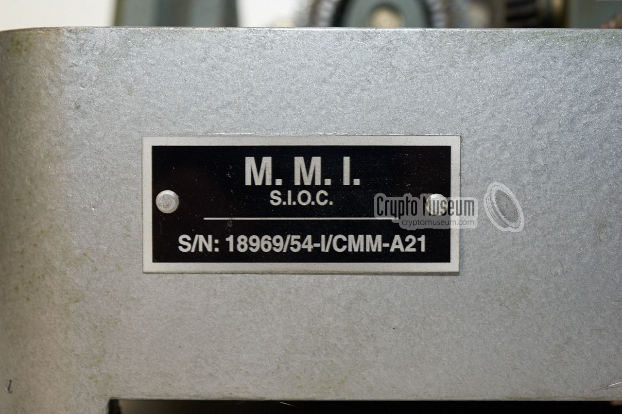
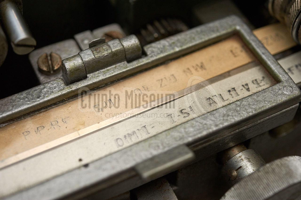
The machine shown here was used by the Military Operational Intelligence Service
3 (SIOC) of the Italian Navy 4 (MMI),
as indicated by an extra name tag at the rear.
The name tag also suggests that this machine is based on the
1954 model.
It is believed that the Cryptograph-CR
and the Mk II variant were
the last OMI cipher machines to be made. There are not many
surviving examples.
|
 |
-
After the modification, the machine kept its original model name
'Cryptograph-CR'. The suffix 'Mark II' has been added by ourselves
to identify the modified or upgraded version.
-
At some places on the machine's body, the old green hammerite paint
is still partly visible.
-
SIOC = Servizio Informazione Operazione di Combattimento.
-
MMI = Marina Militare Italiana.
|
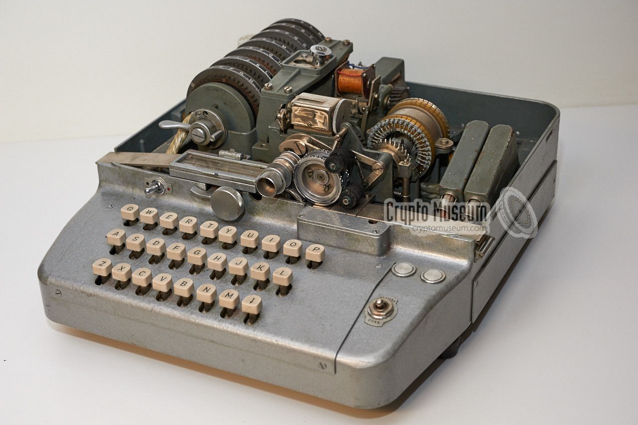
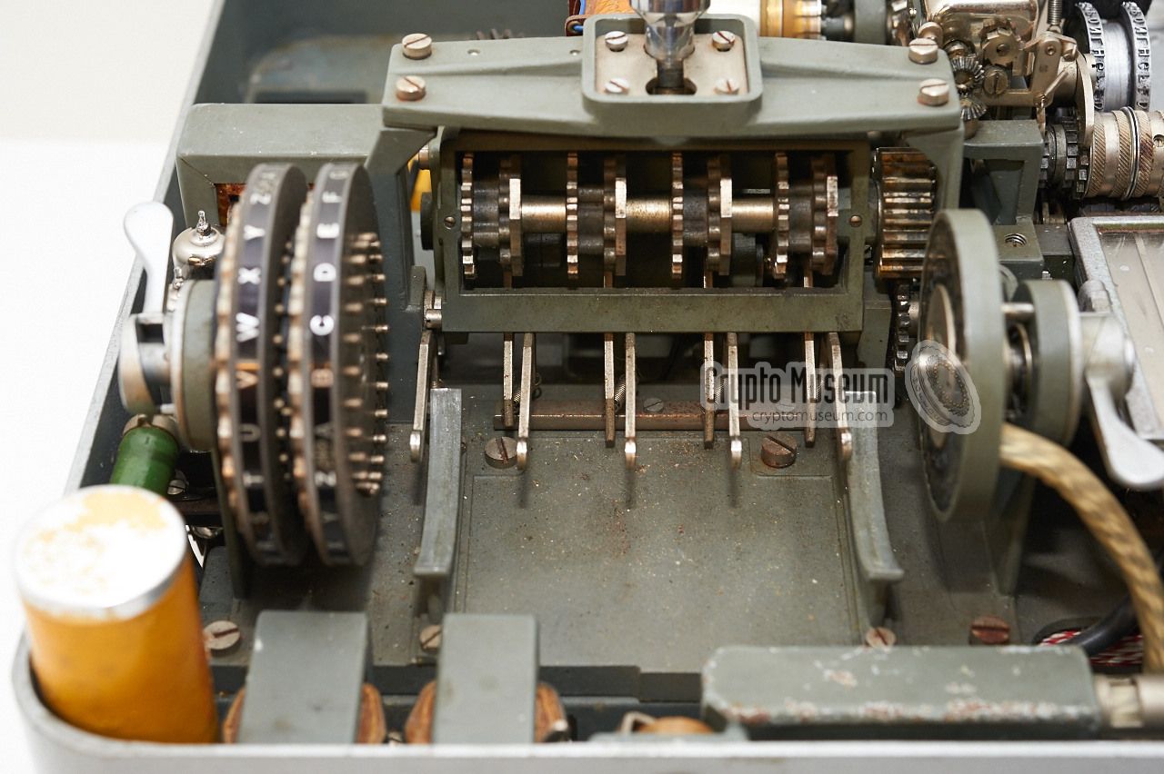
The diagram below shows the various controls and features of the
OMI Cryptograph-CR Mark II. The upper section of the interior is largely
identical to that of the original Cryptograph-CR, but the keyboard
section is completely different. It now carries all 26 letters of the
Latin alphabet (A-Z) plus a paper-advance key. Furthermore, the keys
are placed closer together, making it easier to operate.
The print-enable switches at the right (plaintext and ciphertext)
have been removed.
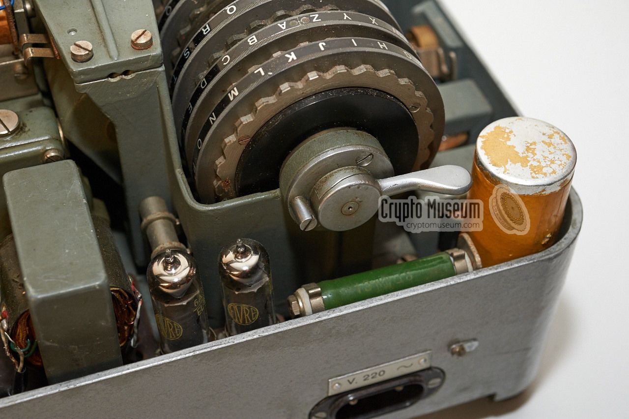
The motor compartment is at the rear right. Note that the motor is missing
from the machine shown above. The paper strip printer is placed just
above/behind the keyboard. The cipher wheels are at the left, with a
mechanical (cogwheel) coupling to their right. The cipher wheels can be
released by unlocking two levers: one at either end of the axle.
|
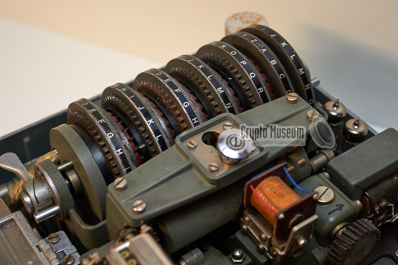
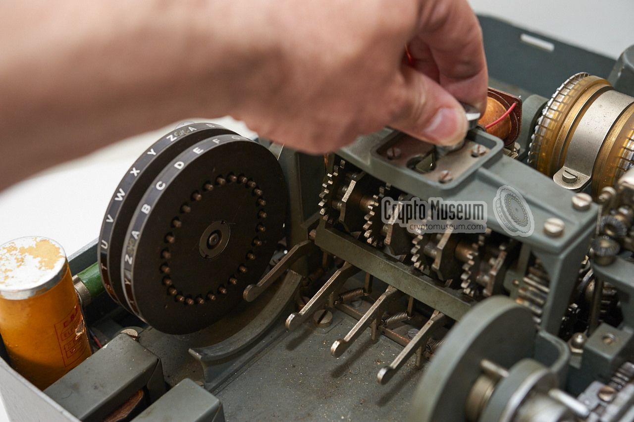
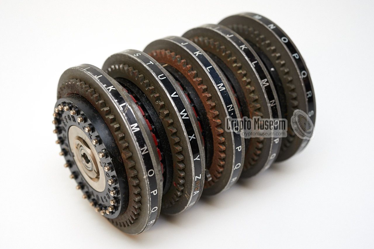
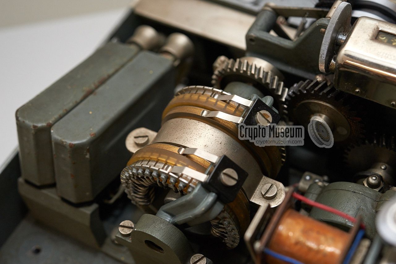
The cipher wheels are located inside the machine, left of the centre,
with the longitudinal axis running from the front of the machine towards
the rear. Each wheel has 26 contacts at either side and, hence, has 26
possible positions, each of which is identified by one of the letters
of the Latin alphabet (A-Z). The letters are printed in such a way that
they are readable from the position of the operator. There are 7 wheels
in total, 5 of which are mounted on a removable axle. The full wheelset
is known as the 'drum'.
Now look at the drum from the left side of the machine:
The drum consists of five moving cipher wheels, a stator and a reflector.
The cipher wheels are moved when a message is entered on the keyboard.
The stator does not move, but can be set to any of its 26 positions.
The reflector doesn't move either, but like the stator it can be set
to any of its 26 positions. Only they 5 cipher wheels can be removed.
They are mounted on a spindle.
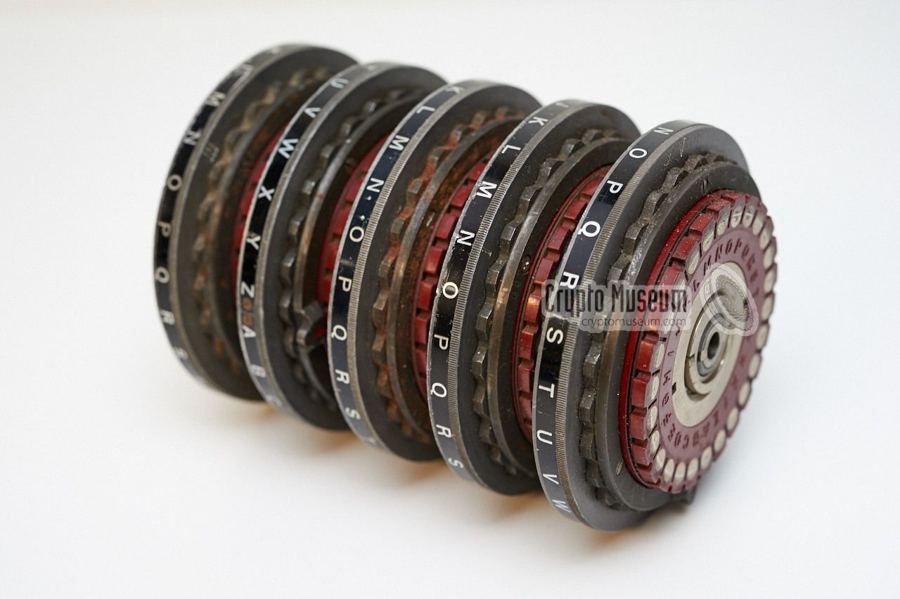
The operation of the drum and the flow of the electric current is very
similar to that of the Enigma.
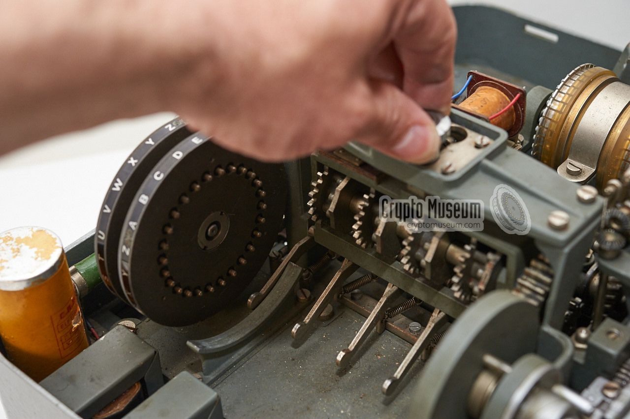
The wiring from the keyboard is connected
to the entry disc
at the far right, which consists of 26 flat-faced
contacts. From there, the current enters one of the spring-loaded
contacts of the rightmost wheel. The wiring inside the wheel
transposes the current to one of its flat-faced contacts at the left side.
This way, the current passes through all 5 cipher wheels and the Stator (S),
until it arrives at the Reflector (R)
on the left. The current is then returned.
The simplified schematic diagram above shows how the current flows
from the entry wheel, through the cipher wheels, the stator, the
reflector and back. The entry path is shown in red, whilst the return
path is blue. In the example, the letter 'A' is encoded into 'D'.
Due to the fact that a reflector is used, the path is reciprocal (reversible).
This means that, at the same settings and positions
of the wheels, the letter 'D' would be encoded into 'A', just like
on the Enigma.
It also means that the machine has the same weakness as Enigma, in that
a letter can never be encoded into itself. In other words: if 'A' is
pressed, it can become any letter, but never the 'A'.
|
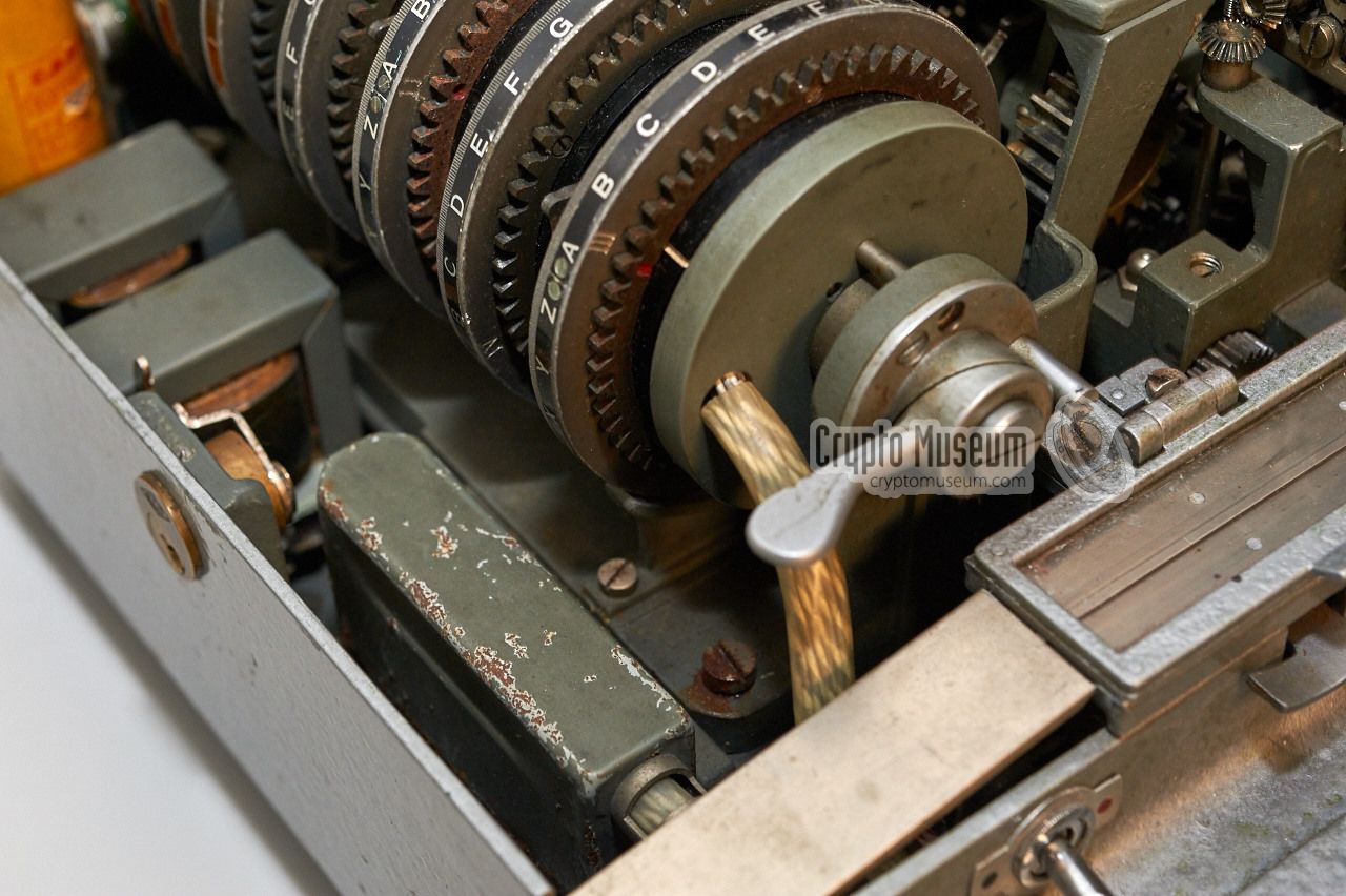
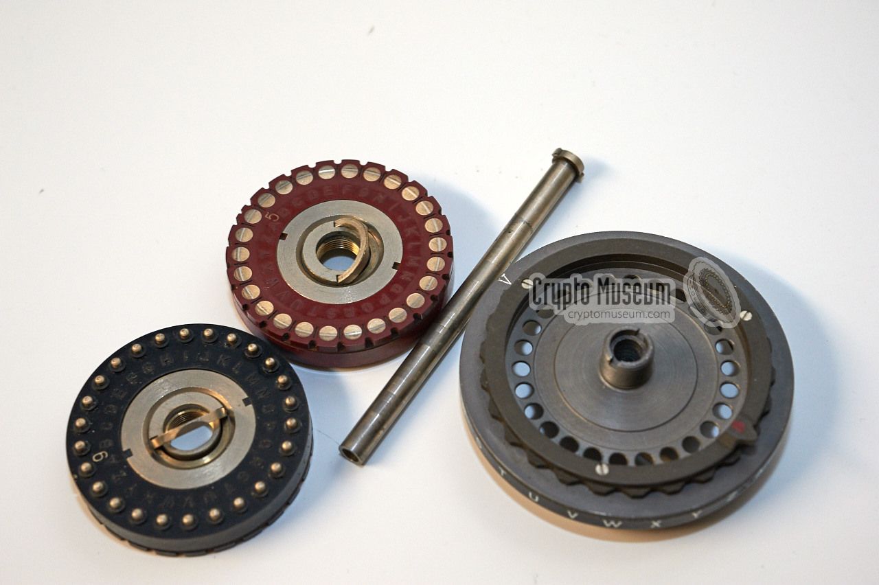
The 5 cipher wheels (i.e. the rightmost five wheels when looking
at the drum from the left side of the machine) are mounted on an
axle that can be removed by releasing the drum-locking levers at
either end of the drum. Before doing this however, the
gear coupling
behind the wheels (again when looking from the left side) should
be disengaged first.
The spindle can now be removed.
Before removing the wheels from the spindle, the stop at one
of its ends has to be removed using a special tool (if supplied).
If this tool is not present, a large screwdriver that precisely fits
the slit can be used as an alternative. The wheels can now safely
be removed from the spindle.
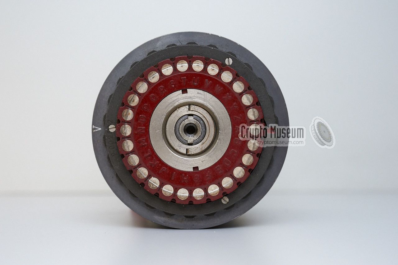
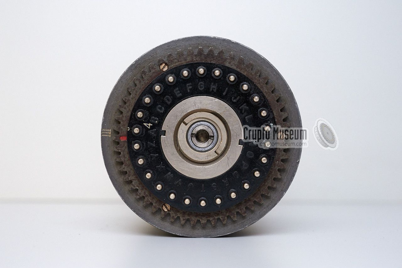
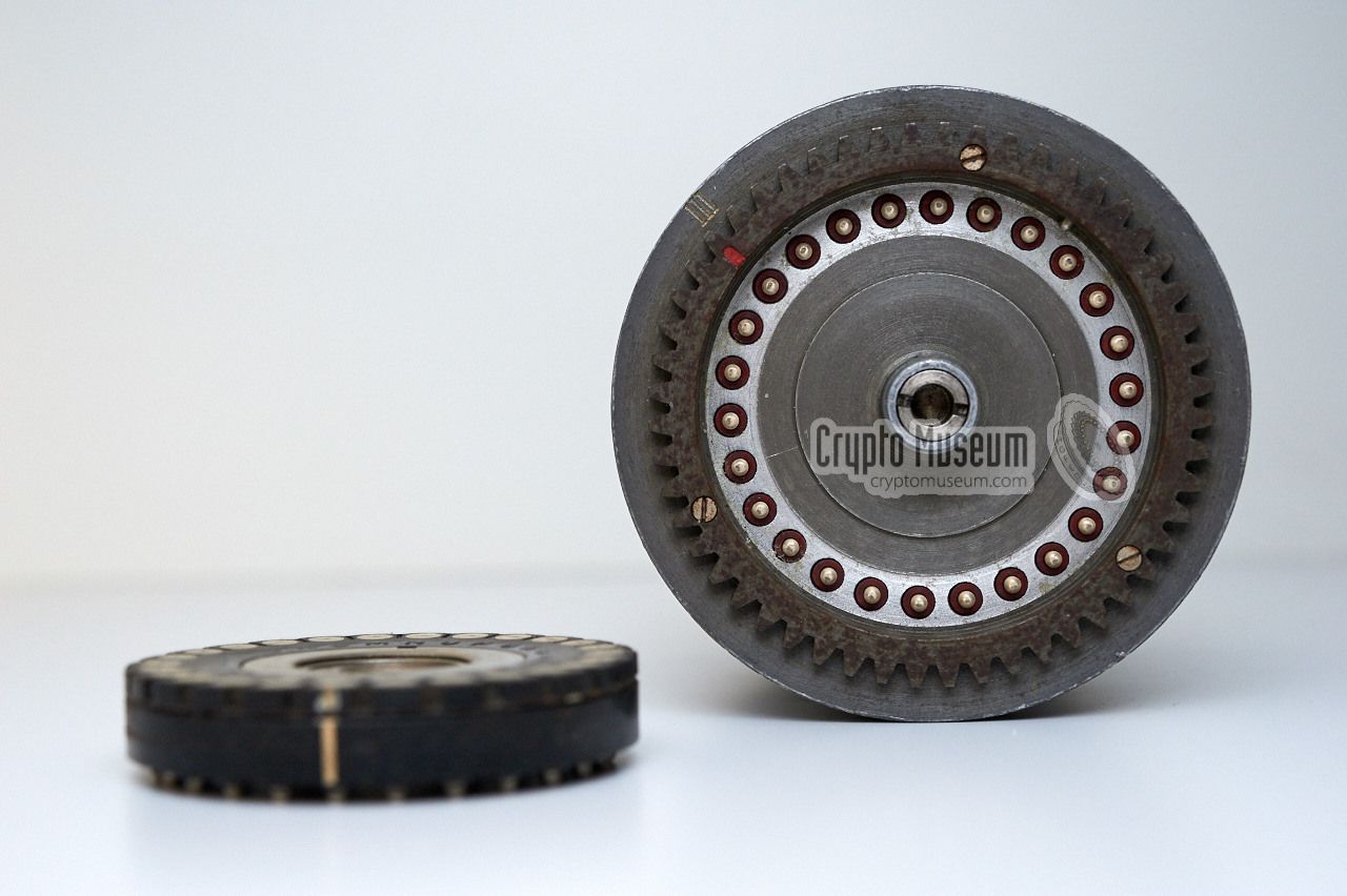
Each cipher wheel consists of three main parts: a metal frame,
a red wiring core and a black wiring core, as shown in the image
above. Although each frame has a unique number (I thru V), they
are all identical and have a wheel-turnover notch at the letter 'A'.
Each wheel is fitted with two unique wiring cores: a black one
and a red one. The black one is always fitted at the right (or
the front when seeing it from the operator's perspective) with the
spring-loaded contacts facing outwards. Likewise, the red core is
always at the left with its flat-faced contacts facing outwards.
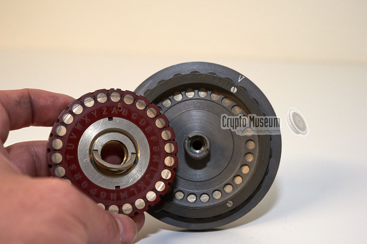
The frame is no more than a die cast holder for the two cores,
each of which can be inserted in 26 different positions. The red core
is always inserted from the left, in such a way that the 26
spring-loaded contacts mate with the 26 holes in the centre part of
frame. The core is then screwed to the frame using using the fold-out
clip at the centre. In the same way, the black core can be inserted
into the right side of the frame in 26 ways, and is secured
in place with the clip.
|
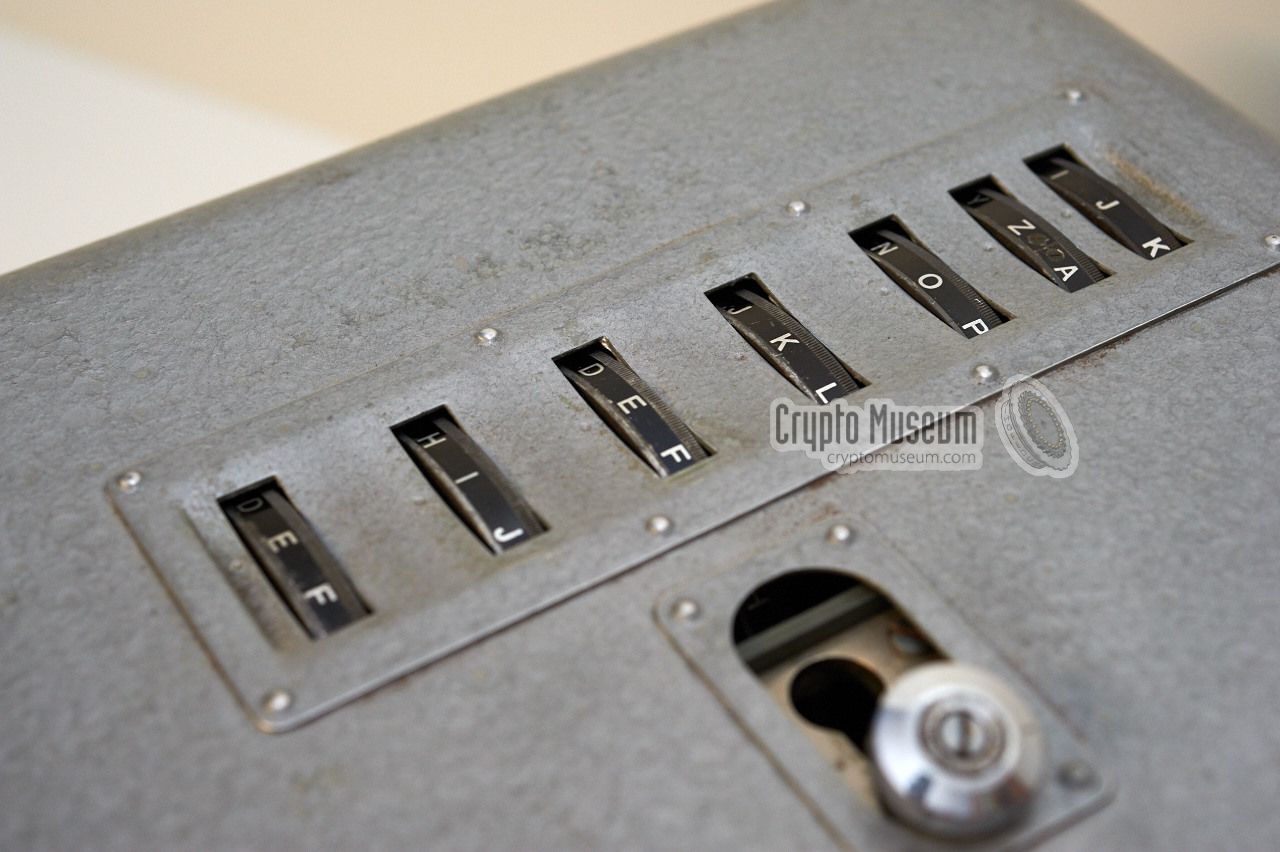
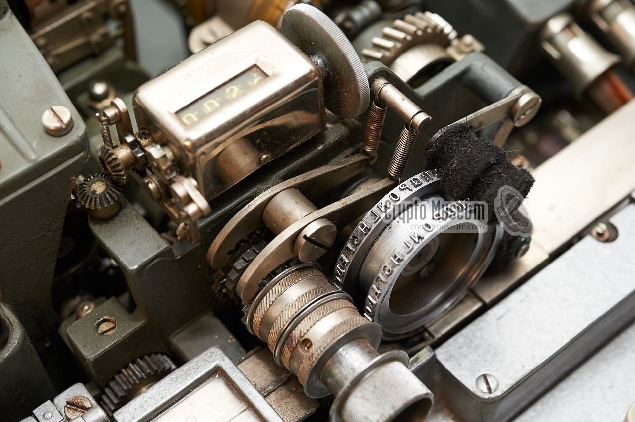
When the top lid of the case is in place, the 7 wheels protrude
the top surface of the lid so that their position can be viewed
and altered.
Each of the wheels has the 26 letters of the alphabet
printed around its circumference, in such a way they can be read
by the operator when operating the keyboard. The wheel stepping
mechanism shows great resemblance to that of the
Zählwerk Enigma,
in that it is driven by cogwheels. This allows corrections to be
made, simply by turning the advance/reverse knob just behind the
keyboard. Each wheel has only one turnover notch.
When typing a character on the keyboard, the rightmost wheel
(i.e. the wheel closest to the front of the machine) moves
counter clockwise (from the operator's perspecitive) to the
next position. This means that after 'A' the 'B' shall be visible.
As each frame has only one turnover notch, this means that the
second wheel will make a single step after a full revolution of
the first one.
Note that the turnover notch, or cam, is mounted to the wheel
aside the letter 'A', but will only cause the next wheel to step
when the letter 'T' is visible in the window at the top of the machine.
The Stator (S) and Reflector (R) do not move. To illustrate the stepping
of the five cipher wheels, we show three successive steps of the fast wheel,
as seen from the operator's position:
|
Each machine was supplied with at least 5 black cores and 5 red cores,
but additional cores were often provided to increase
the possible key space. Each core is marked with a white number that is
engraved between the A and B contacts. As an example, the drawing below
shows both sides of red core number 3 and black core number 4.
Each combination of a red and a black core forms a complete cipher
wheel and each core can be inserted in the frame in 26 different
positions.
In the original description, black and red
cores are referred to
as front and rear cores respectively
[2].
At both sides of the core, the alphabet (A-Z) is embossed in the
bakelite surface as an index. Note that in both cases, the alphabet
runs clockwise, which means that it should only be used as a reference
when inserting the core into the frame. It should not be used when
describing the wheel wiring
or algorithm. Only the letters 'A' and 'N' are at the same
position on both sides.
Note that on the earlier version of the machine
(i.e. the Criptograph),
the alphabet index letters on the sides of the cores were in a transposed order,
probably to add an extra layer of obscurity. Apparently this transposition was
abandoned on the later Cryptograph-CR. Furthermore, with the earlier
Criptograph,
odd numbers were used for the front cores (black) and even
numbers for the rear cores (red).
With the later machines, this no longer seems to be the case, but there
are indications that numbers were not duplicated (e.g. if there is
a red core 3, there is no black 3).
The following cores were found in the Cryptograph-CR Mk II that is featured
on this page [1]:
|
|
The table below gives the wiring of the OMI Cryptograph-CR Mk II
that is featured on this page. Please note that the wiring is
given relative to the A-Z index that is present at both sides
of each wheel. Please note that the A-Z index runs clockwise
at both sides (when viewing the contacts).
|
| Wheel | Colour | ABCDEFGHIJKLMNOPQRSTUVWXYZ | Remark |
|
|
| 1 | red | KOYVZTLGUDUMSBNWFRHQPXCAJE | |
| 2 | red | HUEDLQRPNKIGBAFWYSJCOTMVZX | |
| 3 | red | OLXGPIBAUFWKDTZSCHYJNRQMEV | |
| 4 | black | QHECYSZGFIJONPTRLWAVKMUBXD | |
| 5 | red | PDYOTMQXUKASILCJHRBGVNEWFZ | |
| 6 | red | ZHPGOLENQFYTDWRSKAJCBMXUVI | |
| 7 | black | EUAMCTPGKSFQBXHRJYLONZVWID | |
| 8 | black | YDKPRVALSCOUZGWMJNXQTBHIFE | |
| 9 | black | YTOQUJXZFKVNAMPXSBWREHGLDI | |
| 0 | black | UWJRZVXTYLDPEHCSNGKMOGIQAB | |
| S | - | EDQTLAIXMFSONBZGRHKPYWCVJE | Stator |
| R | - | NDMBITWZERYXCASUCJOFPQGLKH | Reflector |
|
The above table gives the physical wiring, taking into account that
the A-Z index is different on each side of the wheel. Only the letters 'A'
and 'N' are at the same position. In order to use the wiring for a proper
description of the algorithm, the following transposition should be applied:
|
| Index on the output side of the disc (left) | ABCDEFGHIJKLMNOPQRSTUVWXYZ |
| Corrected index for the output side | AZYXWVUTSRQPONMLKJIHGFEDCB |
|
|
The logical wiring of the wheels is obtained when applying the above
transposition table to the output side of each disc. For this we assume
the right side (i.e. the spring-loaded contacts) to be the input, and the
left side (i.e. the flat-faced contacts) to be the output. The table below
gives the logical wiring for each wheel, relative to the A-Z index
on the input side (right).
|
| Wheel | Colour | ABCDEFGHIJKLMNOPQRSTUVWXYZ | Remark |
|
|
| 1 | red | QMCFBHPUGXSOIZNEVJTKLDYARW | |
| 2 | red | TGWXPKJLNQSUZAVECIRYMHOFBD | |
| 3 | red | MPDULSZAGVERQHBIYTCRNJKOWF | |
| 4 | black | KTWYCIBUVSRMNLHJPEAFQOGZDX | |
| 5 | red | LXCMHOKDGQAISPYRTJZUFNWEVB | |
| 6 | red | BTLUMPWNKVCHXEJIQARYZOGDFS | |
| 7 | black | WGAOYHLUQIVKZDTJRCPMNBFESX | |
| 8 | black | CXQLJFAPIYMGBUEODNRKKZTSVW | |
| 9 | black | CHMKGTYBVQFNAOLDIZEJWTUPXS | |
| 0 | black | GERJBFDHCPXLWTYINUQOMVSKAZ | |
| S | - | GXKNPASDOVINMZBUJTQLCEYFRW | Stator |
| R | - | NXOZSHEBWJCDYAIGFRMVLKUPQT | Reflector |
|
|
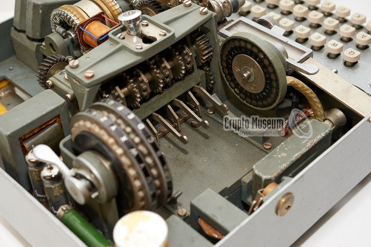
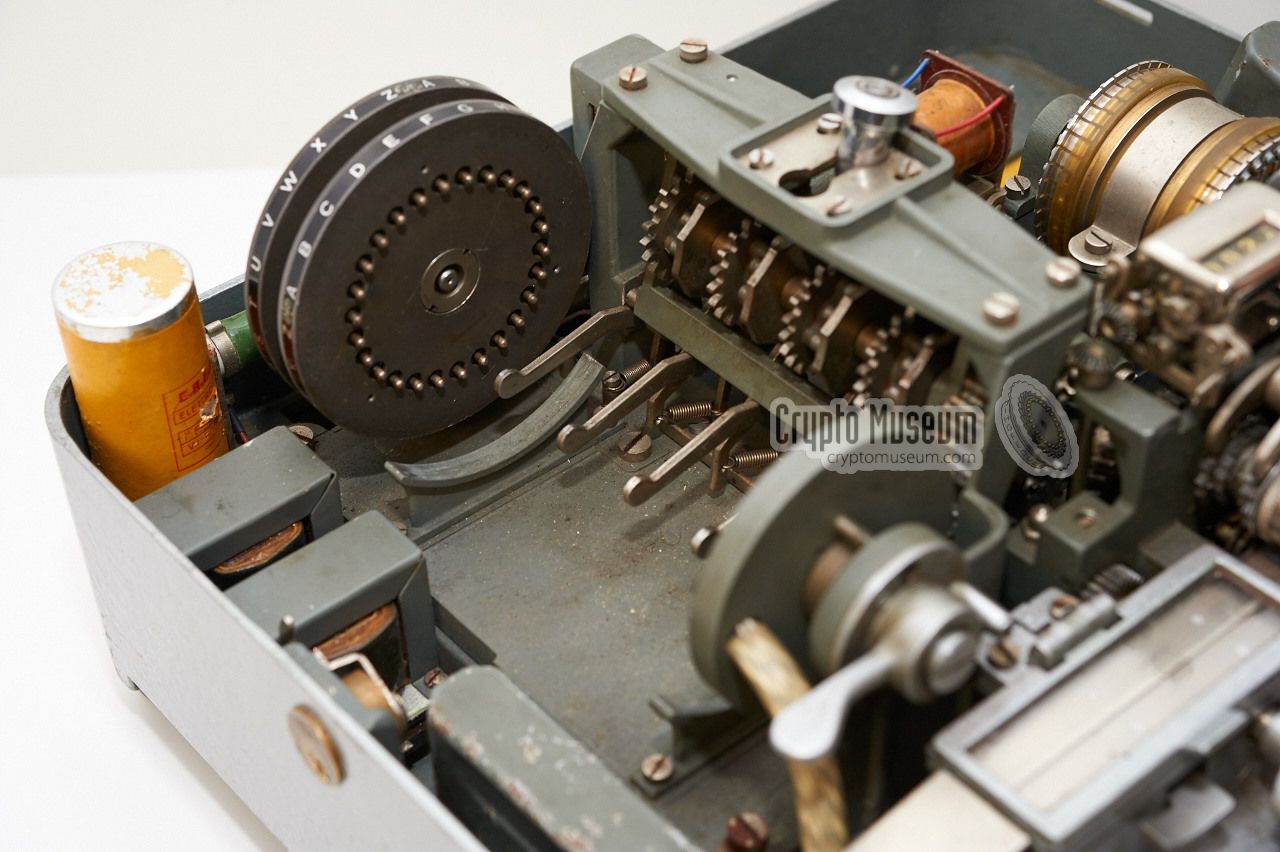
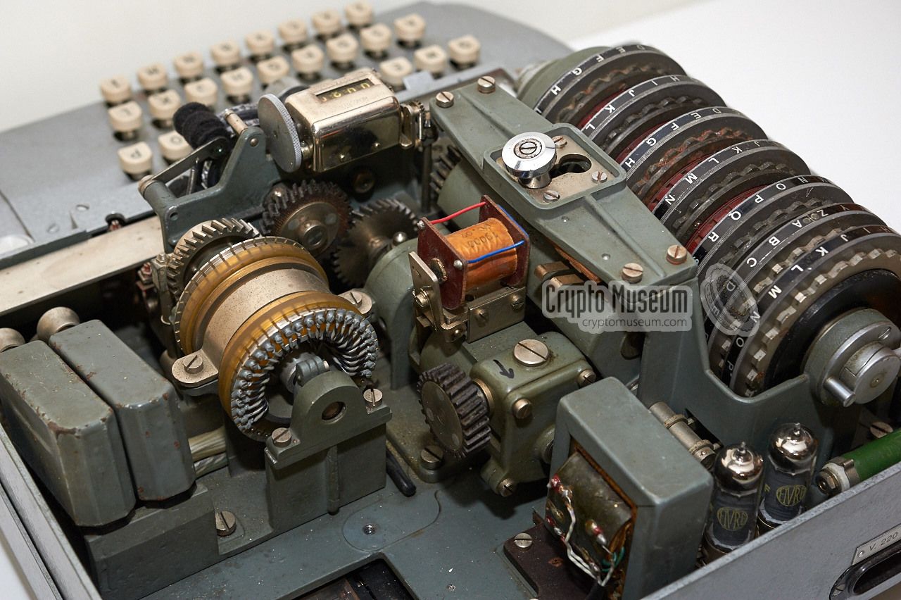
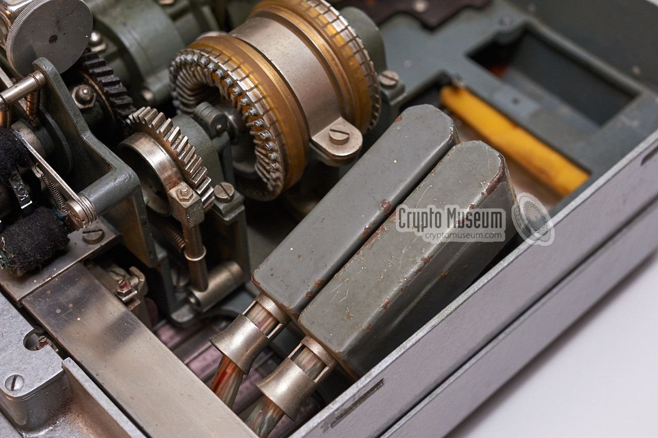
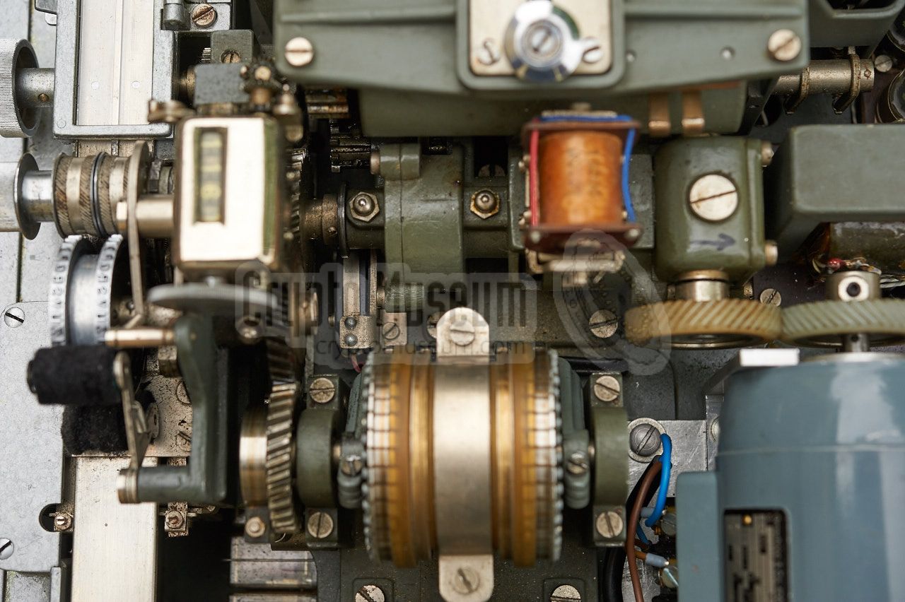
The interior of the machine can be accessed from both sides: the top
and the bottom. At the top are the mechanical parts, such as the cipher
wheels, the printer, the main driving axle, the motor and the commutator.
At the bottom are the electric parts, like the power supply and the relays.
|
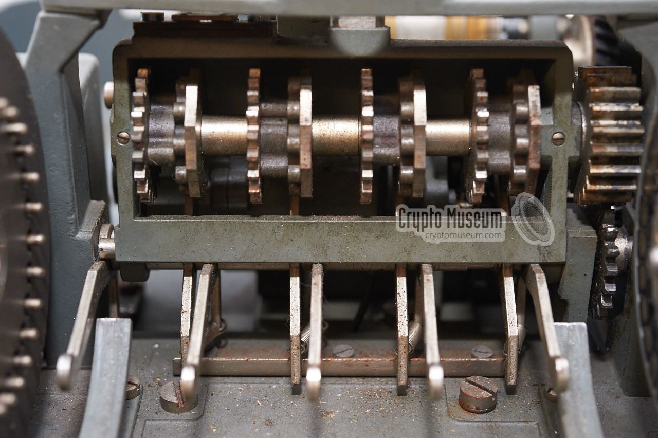
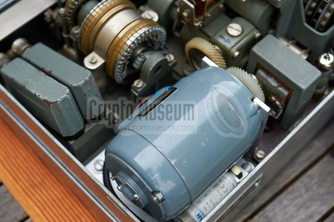
The main driving axle
is placed at the center of the machine, running from
rear to front. It has an electric coupling and is driven by an electromotor
that is placed at the rear right. Note that the motor is missing from the
machine shown here, but that it has since been replaced as part of the
restoration process. The printer,
also visible in the image, is placed
at the front end of the driving axle, just behind the keyboard.
The printer features two alphabets:
one for the ciphertext and one for the plaintext.
A paper strip runs right-to-left below the print heads.
|
|
|
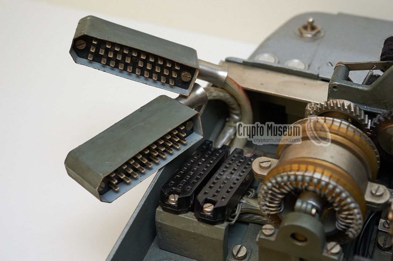
The two print heads are coupled, so that they always rotate synchronously.
Each print head has a hammer, mounted below it, that ensures that the
correct letter is printed onto the paper strip. These two print hammers are
driven asynchronously, under control of a
double commutator.
|
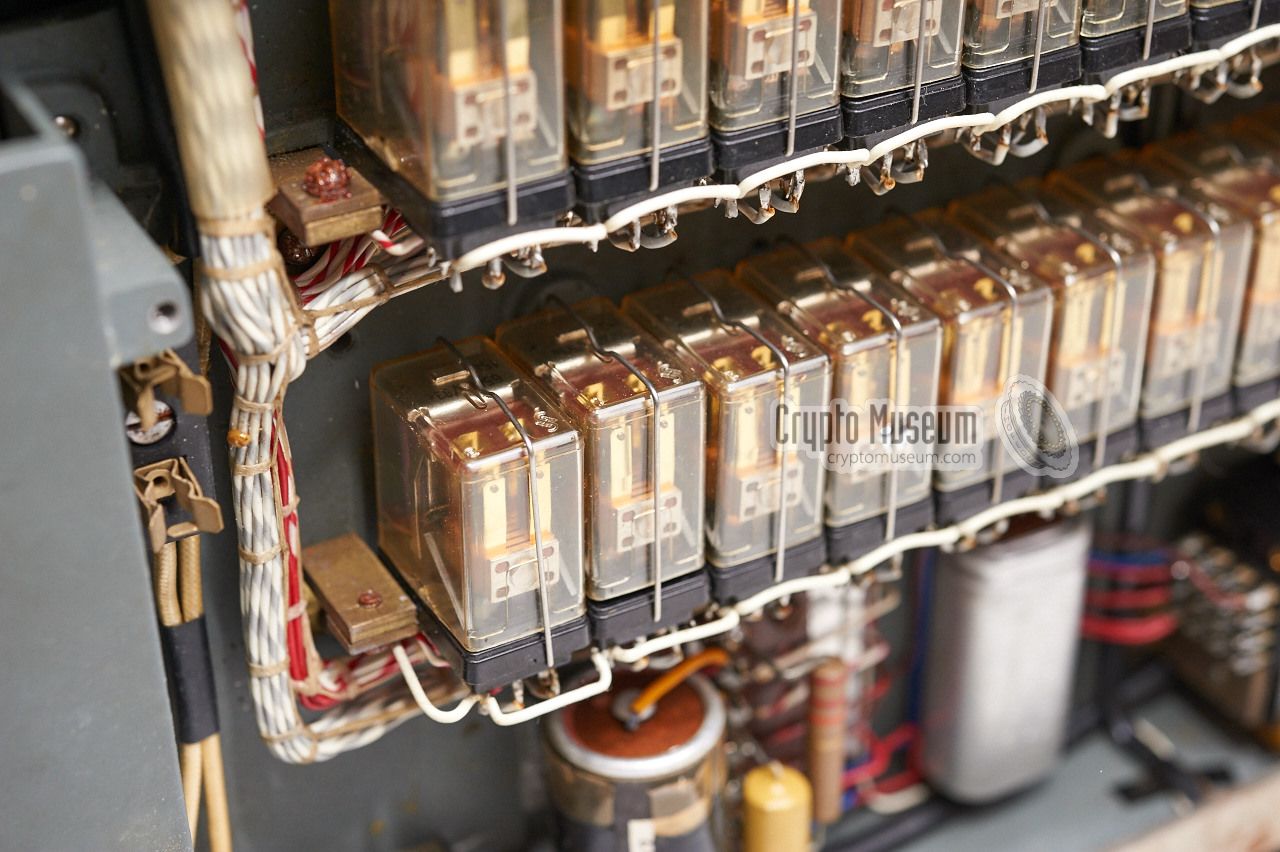
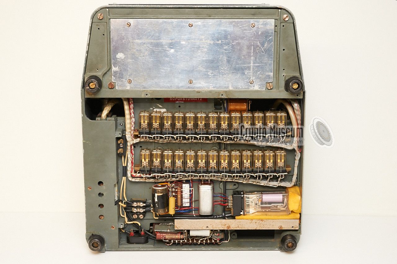
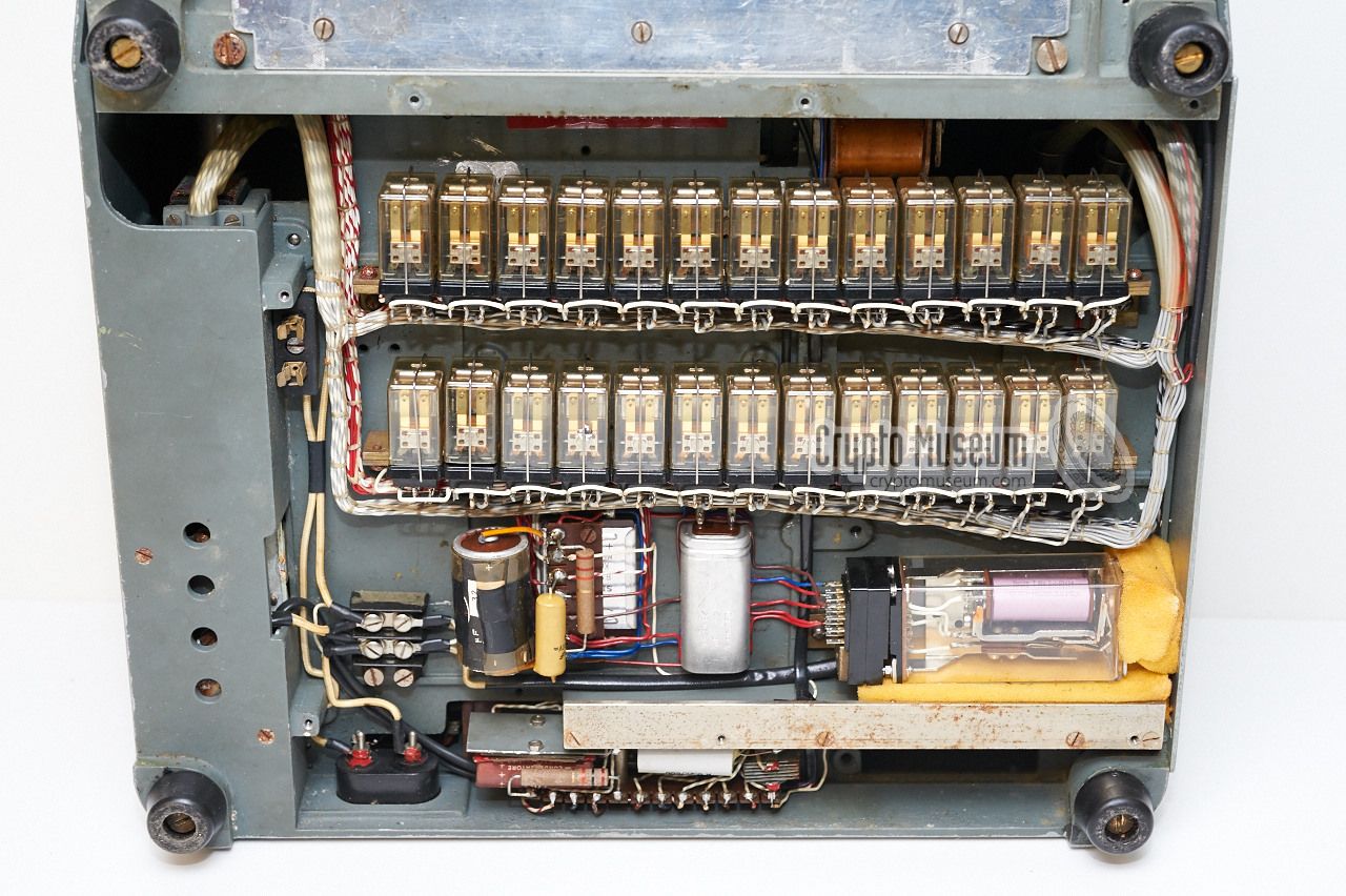
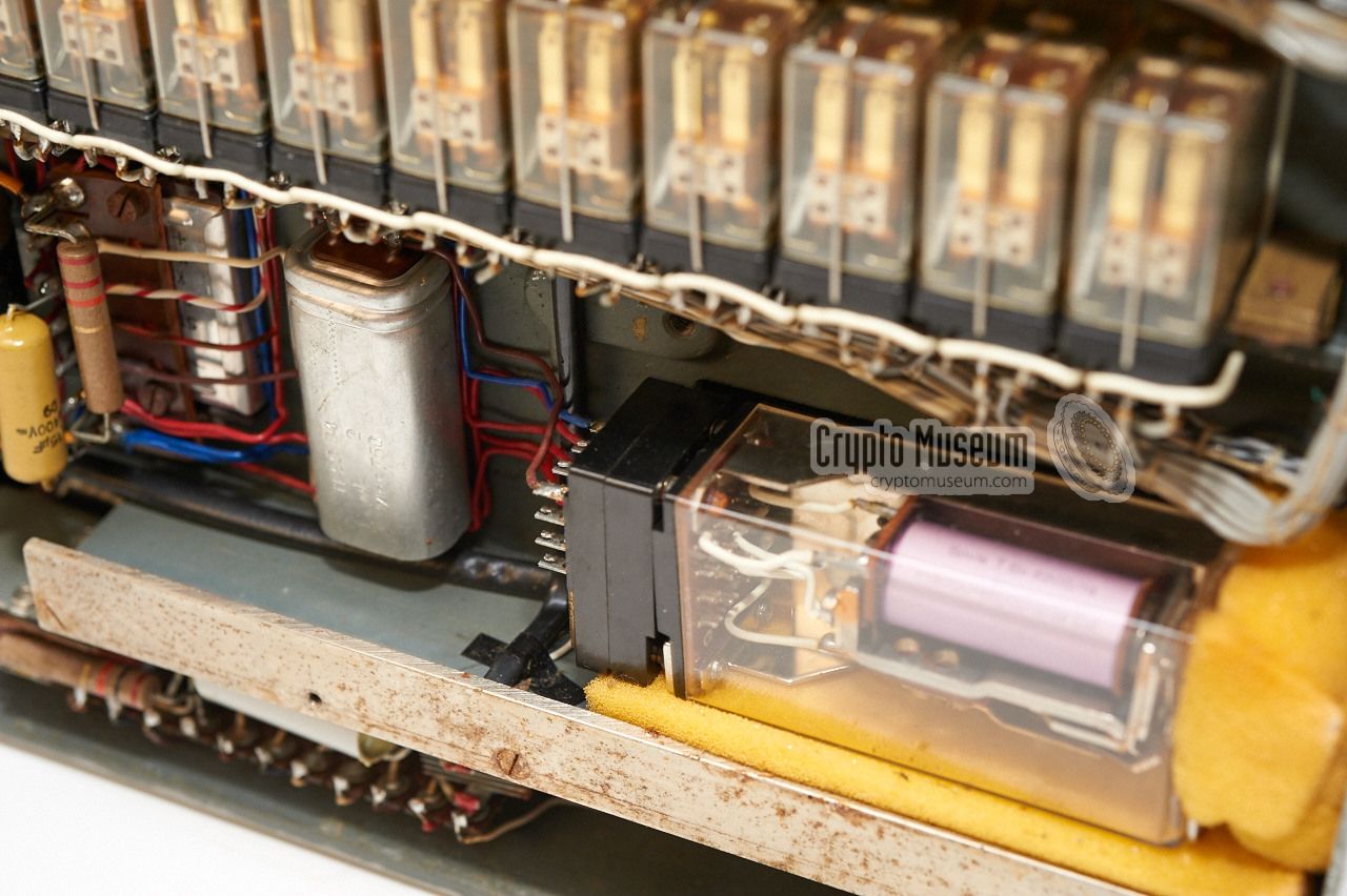
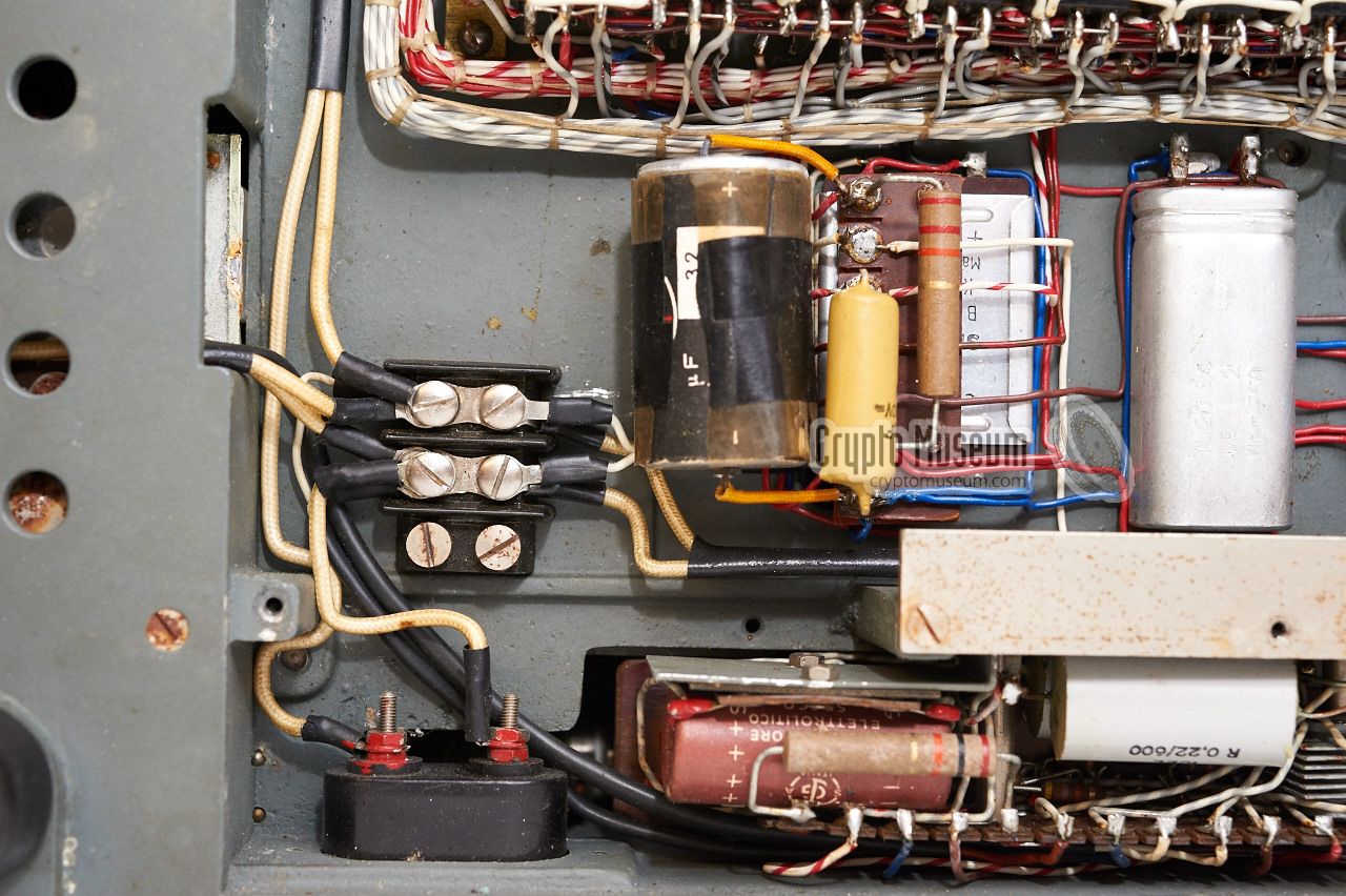
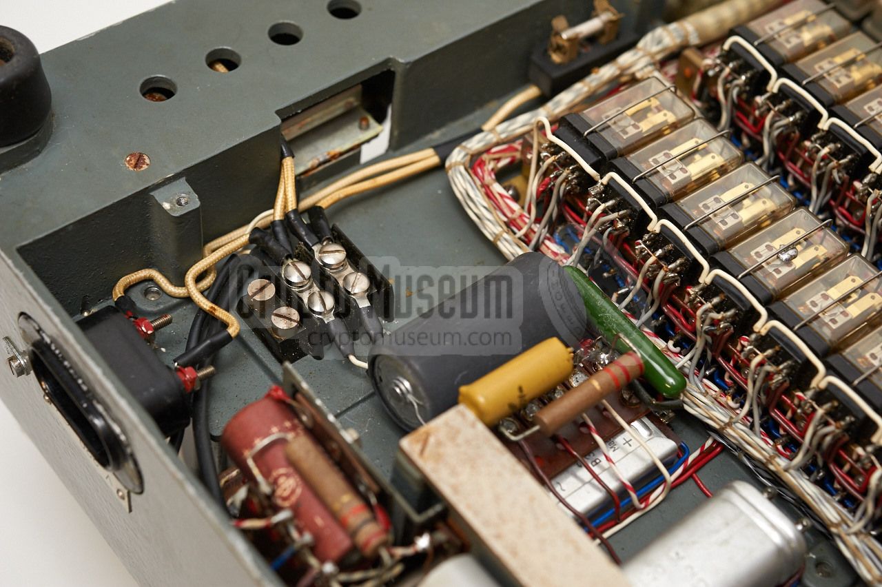
The bottom side
of the machine contains the electric components, such as
parts of the power supply unit (PSU)
and the mains transformers.
This side is completely different from the earlier
Cryptograph-CR.
The paper tray has been given up and its space has been used to accomodate
a set of 26 electric relays, organised as
two rows of 13 relays each.
Each relay is driven by one of the keys on the keyboard and offers 4
sets of contacts. In addition, a fairly large
master relay is mounted towards
the rear. It drives the main coupling and is controlled by the
other relays.
|
|
|
The reason for adding the 26 relays to the design was probably to lower
the current through the keyboard contacts, especially when driving the
coupling. Furthermore it simplifies the keyboard.
For a detailed description of the working of the machine, please
refer to the circuit diagram.
|
The drawing below show the circuit diagram of the Cryptograph-CR Mk II.
The mechanical parts are at the right and are shown in blue. The machine
has three individual power supply units (PSU). PSU 1 provides the +250V
DC voltage to drive the relays (V1).
PSU 2 provides the voltage for the cipher drum (V2)
and PSU 3 provides the HT and LT voltages
for the valve-based solenoid drivers.
After turning the machine ON, the motor starts running, but the
other mechanical parts are in rest. As soon as a key is pressed,
the corresponding
relay (Re) is activated which in turn activates the main relay (VC)
that drives a solenoid driven coupling. The coupling sets the main shaft in
motion. A Hold Switch, activated by a tacho disc on the main
shaft, ensures that the activated relay is held (VH) and that
the coupling is released after one full revolution of the main shaft.
For each of the 26 letter keys on the keyboard, a Siemens 4-pole double-throw
(4PDT) relay is present. The first switch of this relay is used as a hold
contact. It is connected to the Hold Switch (VH) to ensure that
the relay remains activated whilst the main shaft is in motion. The second
contact is used to drive the coupling solenoid (VC) that sets the
main shaft in motion.
The third switch is used for the actual encryption of the letter and is
similar to a keyboard switch on the Enigma cipher machine. It supplies
a voltage (V2) to the corresponding contact of the Entry Disc (ED).
Once the letter is encoded, the returned signal is sent to the
Ciphertext Printer (C2). As the machine also has a Plaintext Printer,
the 4th relay switch is used to drive that directly (C1).
|
The Cryptograph-CR has two built-in paper strip printers at the front of
the machine. The rearmost one is used for showing the plaintext, whilst
the one at the front is used to print the ciphertext. The two printheads
are identical and are driven by the same shaft. Two individual commutators
(C1 and C2) that are also driven by this shaft, determine
the precise moment to activate each of the printer hammers. The hammer
pushes the paper strip against the print head.
Note that commutator and print head rotate in synchronism.
As the current that is needed for the hammer solenoid is too high for
the cipher wheels, a valve-based theratron amplifier is used.
The CIPHER/DECIPHER switch to the right of the keyboard (CLEAR/CIPHER)
simply swaps the two amplifier inputs, so that the plaintext also appears
on the rearmost printer when decoding.
|
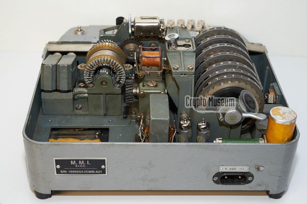
June 2016
The machine featured on this page belongs to Austrian collector Günter Hütter
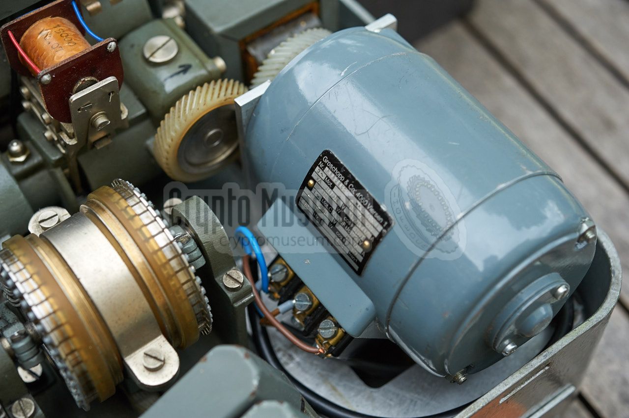
[1], and has now been fully restored so that it can be demonstrated again.
A suitable motor with appropriate gear and the correct speed has been mounted
in the empty space at the rear right, as shown below.
|
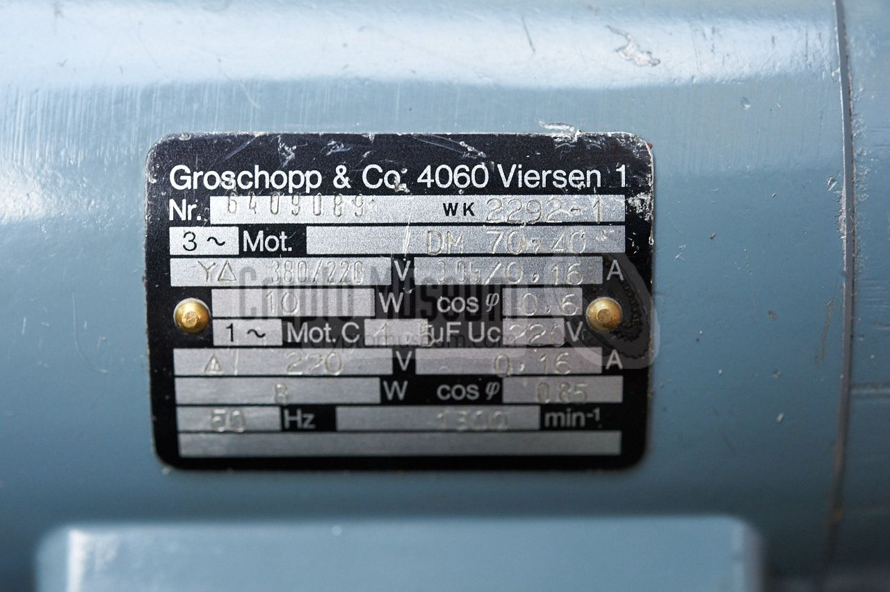
Although the speed of the motor is not crytical, it has to be sufficiently slow
to allow the various parts of the cipher mechanism and the printer to move
smoothly. The replacement motor has a speed of 1300 RPM, which appears to be
perfect.
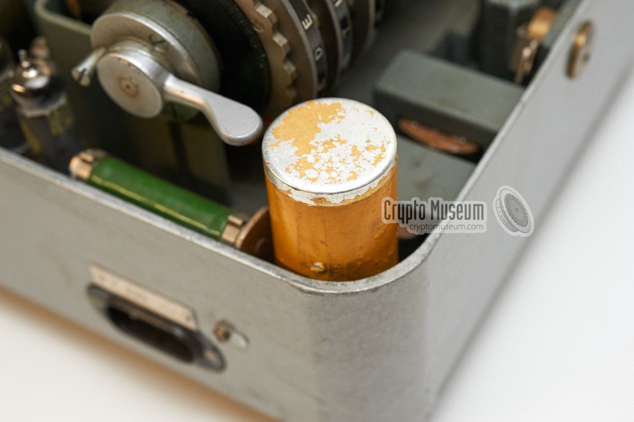
The selenium rectifier bridge and the electrolytic capacitor of the
200V DC power supply
turned out to be broken and had to be replaced.
The coil of one of the individual alphabet relays
was also broken but could not be repaired.
Luckily, an identical replacement relay of the same type, spec and build date
was found in the junk box.
|
|
|
Once the broken parts were replaced, the contacts of the rotor basket
were cleaned and the gear box was properly greased again,
it was time to put to the motor in action for the first time after many years.
The mechanism worked straight away and after adjusting the commutator (to
meet the speed of the new motor) a text was enciphered and
deciphered correctly. OMI is alive again.
|
- Günter Hütter, Cryptograph-CR Mk II
OMI Cryptograph-CR Mk II courtesy Günter Hütter. Photographs: Crypto Museum.
Austria, June 2015 and June 2016.
|
|
|
|
Any links shown in red are currently unavailable.
If you like the information on this website, why not make a donation?
© Crypto Museum. Created: Sunday 20 December 2015. Last changed: Wednesday, 21 February 2024 - 23:24 CET.
|
|

|
|
|
| | |


![OMI Cryptograph-CR Mark II (courtesy Günter Hütter [1]](img/302152/003/full.jpg)


