|
|
|
|
|

|
|
← Motorola Voice
Secure handheld radio
The STX was a series of handheld trunking radios operating in the 800 MHz
or 900 MHz 1 band,
developed by Motorola
around 1991. Some STX radios have built-in speech encryption.
The STX series was used by police forces and by the Ministry of Defence
(MoD) of several countries in the USA and in Europe. The STX can be seen as
one of the successors to the successful SABER series.
|
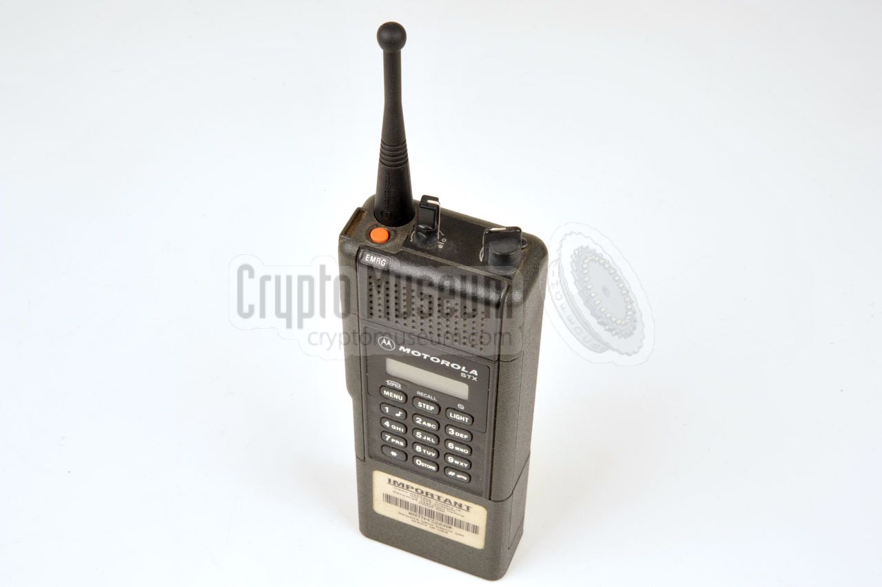
The image on the right shows a typical Motorola STX that is ready for use.
About 2/3 of the body is taken by the radio itself.
The battery takes about 1/3 of the hight and is attached to the
bottom of the radio.
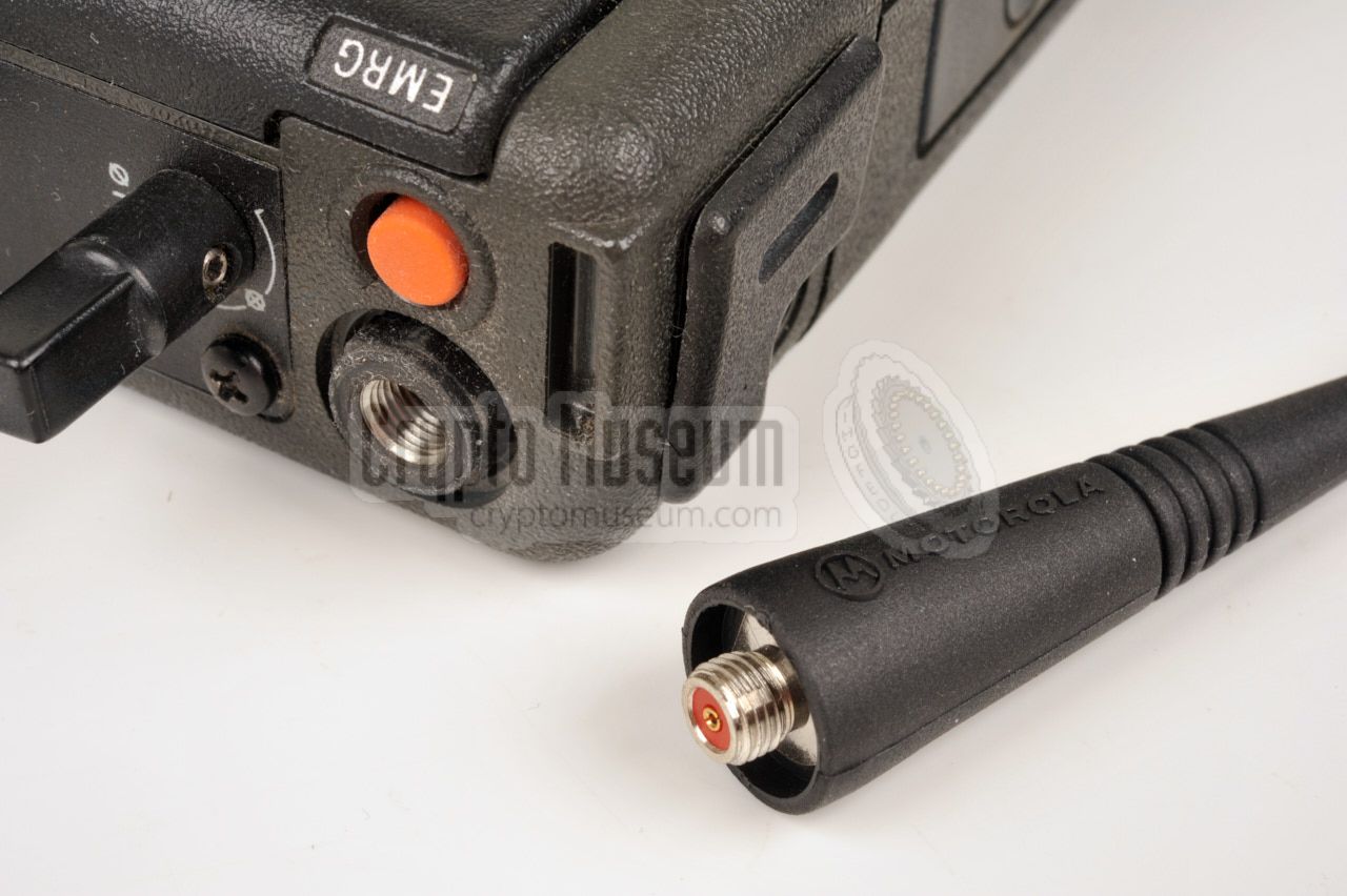
A suitable antenna has to be screwed-in at the
top panel
that also holds the MODE selector and the volume control.
Also on the the top panel is a bright
orange button marked EMRG.
It can be programmed to send a distress signal in case of an emergency.
If the radio is crypto-capable, the channel selector is used to select between
secure and plain.
|
|
|
Peripherals and accessories, such as a speaker/mike or a covert vest,
can be connected to the expansion socket at the left side of the radio,
just below the antenna base. The socket is normally covered by a rubber
cap that protects it against dust and damage. Just below the expansion
socket is a fairly large Push-To-Talk (PTT) button
that has to be pressed during a transmission.
|
-
Most STX radios are 800 MHz models, operating between 821 and 870 MHz,
but there are versions with the same factory ID that operate in the
900 MHz band.
|
The STX is a very compact radio, considering the era in which it
was developed (early 1990s). The top panel holds the antenna,
that is fitted with a screw-in terminal, the volume control and
the MODE selector. It also features a bright orange distress button
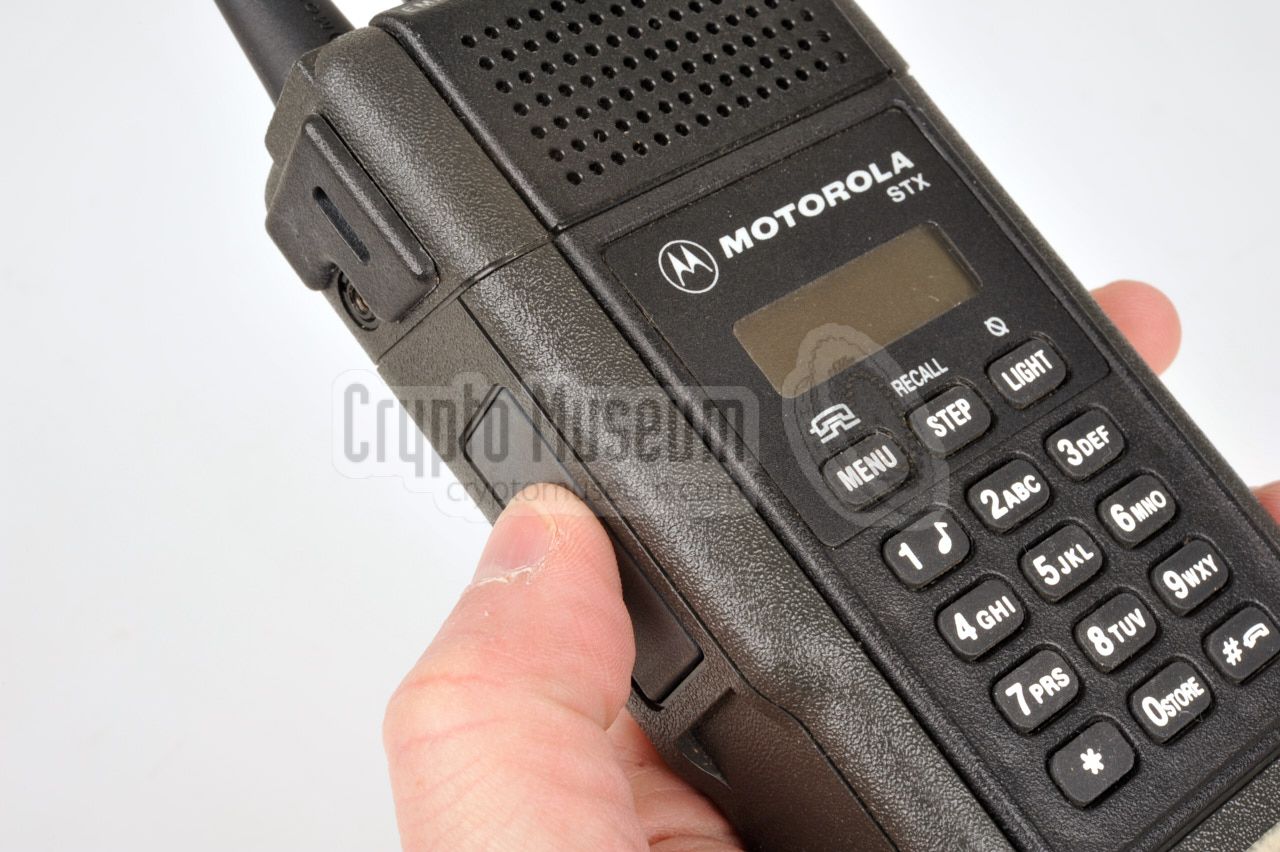
that is marked EMRG. The speaker and the microphone are both located
at the top of the front panel. An external speaker/mike can be
connected to the expansion socket at the left side.
This socket is also used for programming.
Depending on the model, a display and a three or twelve-button
keypad can be present on the front panel. When present, they are
used to access the extended features of the radio, such as
trunking and auto patch (connecting to an analogue telephone line).
|
Bringing an old STX radio back to life can be really difficult
and is not for the faint of heart. First of all you need the correct
Radio Service Software (RSS) for the Motorola STX,
a Motorola Radio Interface Box (RIB) or equivalent,
and a suitable programming cable.
Next you need a DOS-based PC that is
old and slow enough to run the software. And this is the really tricky
part. Check out how we
solved this in the past for the Motorola SABER,
by using a very old Toshiba PC laptop.
Running the software in a DOS shell on a modern PC does not work,
but apparently there is a program called 'DOS Box' which seems to
be able to emulate an old and more importantly slow PC.
Hints and tips on how to program a Motorola STX this way,
can be found on YouTube [1].
|
NMN1004A Microphone with keypad and display NMN1004B Microphone NMN1004D Microphone/speaker with keypad and display NMN6177A Microphone/speaker NMF6050C Microphone/speaker NLN8858 Rapid charger (for single radio) NLN8988A Rapid Multi Charger HMN1015A Microphone/speaker (water resistant) Converta-Com Mobile adapter with NMN1004D microphone
|
|
The diagram below shows the pinout of the expansion socket at the left side
of the radio when looking into the socket [2]. Connecting a microphone, speaker
and Push-To-Talk (PTT) switch is pretty straightforward, as they are all
connected against ground. The data line (7) can be used for programming the
radio. To read the current version of the firmware, connect the data line (7)
to ground (9) when switching on the radio. The information will then appear
on the display [2].
|
- ?
- ?
- Microphone
- PTT
- ?
- ?
- Data (programming)
- ?
- Ground
- Speaker
|
|
The diagram below shows the pinout of the RIB/RSS programming cable for
the Motorola STX. Suitable cables are difficult to find, so you may have to
use the plug from an old microphone or speaker to make your own programming
cable.
|
|
|
|
Any links shown in red are currently unavailable.
If you like the information on this website, why not make a donation?
© Crypto Museum. Created: Saturday 08 October 2016. Last changed: Tuesday, 09 June 2026 - 16:35 CET.
|
 |

|
|
|