|
|
|
|
|

|
|
Motorola EMU MDT-9100 →
Mobile Data Termial
D-1118 is a mobile data terminal, developed by Motorola
(USA) in the late 1970s.
The terminals were developed especially for use by the police and were
mainly built into police patrol vehicles. The unit is commonly known as the
D1118-MDT, but is also referred to as the D1118-B [1].
|
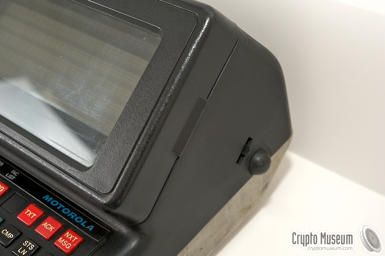
The terminal is housed in a rugged plastic case
and features a 5-row dot-matrix plasma display.
Below the display is an extended keyboard
with the usual QWERTY layout and a row of
red keys marked STS-A to E and MSG-A to F.
All wiring is connected via a
25-pin sub-D socket at the rear.
The image on the right shows a typical D1118 terminal as it has been in use
with the police force for many years. It is difficult to determine its age
as there are no date markings on the device or the PCB,
but judging from the date-codes on the various chips, it was built in 1980.
|
|
|
Different versions and variants of the D1118-B are known to exist,
in particular with different keyboard layouts (see below) and
additional – often customer specific – functionality.
The variant was probably identified by an extension to the model number.
The model shown in the images is identified as the D1118-B SP13.
The extention 'SP' probably stands for 'Special'.
Judging from the date codes on various components, the device
featured here was manufactured around 1980.
Terminals like this were widely used throughout the US.
A variant of it, with messages printed on each key,
was used by the ambulance service in Vienna (Austria) during the 1980s [5].
A version of the D-1118 is briefly visible at the beginning of the movie
The Blues Brothers, in which it is called SCMODS.
|
At the bottom left of the keyboard is a red button marked EMR, which stands
for EMERGENCY. This key has a rig around it to prevent it from being
pressed accidently. The EMR button would be used by a police officer to
send a distress signal.
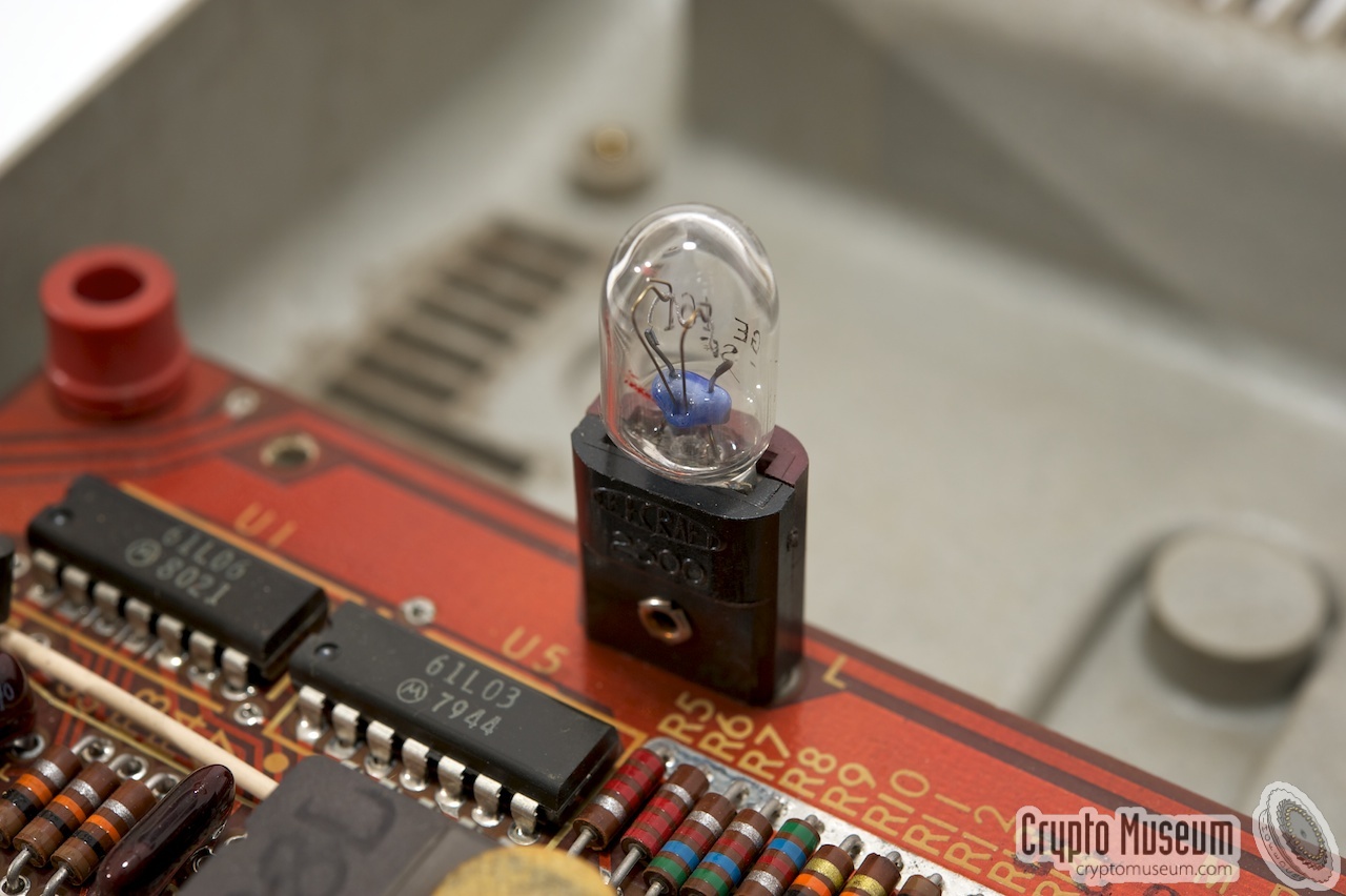
Two slide-switches are present at the front of the terminal. The leftmost one
is the power switch, which is used to turn the terminal on and off and the
rightmost one is the light switch. Both switches are normally labelled, but
with the terminal in the image, the text has come off completely.
The light switch is used to illuminate the keyboard in the dark.
For this purpose, a light is hidden under the display.
|
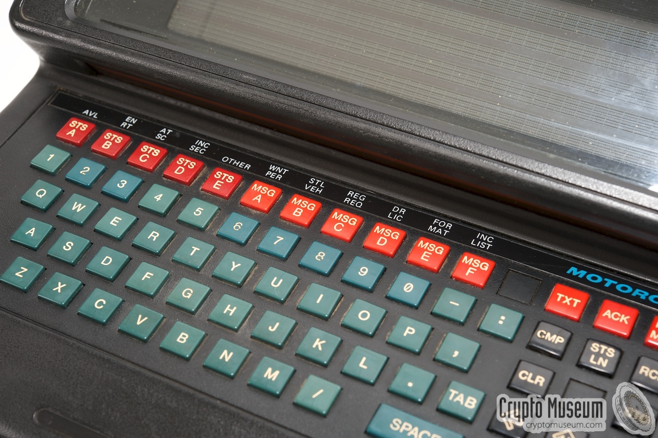
The keyboard has the standard QWERTY layout, with some additional function
keys at the top row. The keys are all marked as STS or MSG buttons, but have
an additional text printed above them. Please note that these markings differ
for the various users and countries. The function keys on the D1118-B
SP13 are different from the ones described by [2].
Furthermore, the layout of the small keyboard extension at the right
may differ from the one shown here.
The function keys are marked as follows:
|
|
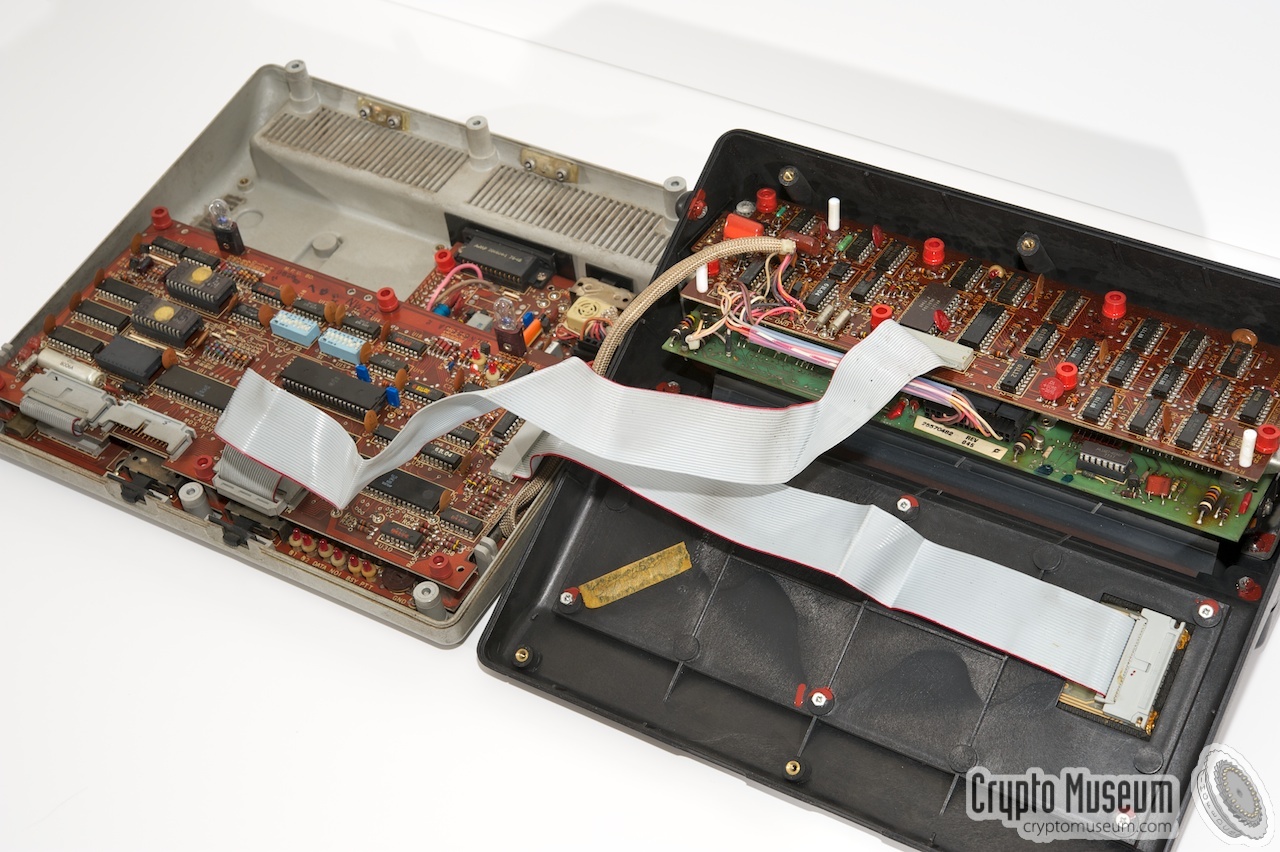
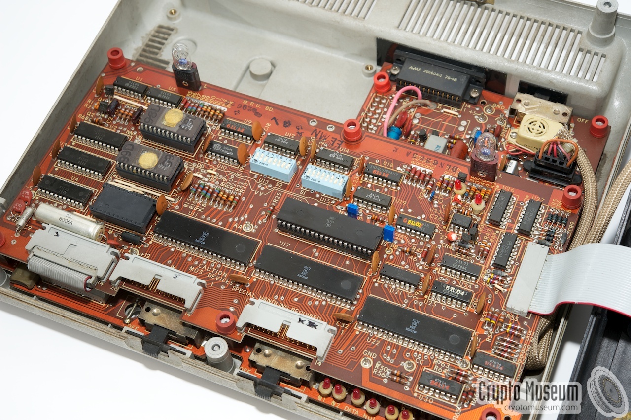
The D1118-B is very service-friendly and can easily be opened by loosening
6 cross-head screws at the bottom. The two halfs (bottom section and top lid)
can be separated without removing the cables.
The bottom section contains two PCBs that are stacked on top of each other.
The top lid contains the keyboard, the diplay and the display controller.
|
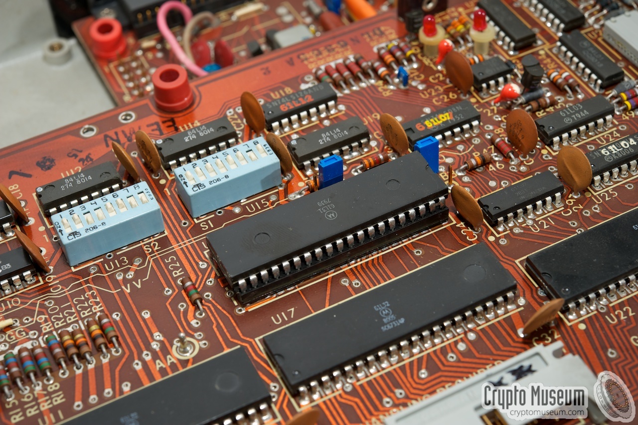
The top board of the bottom section contains the actual CPU, the memory and
the EPROMs with the firmware. The image shows a close-up of the
microprocessor and some of the I/O chips.
The function of the DIP-switches above the processor is currently unknown.
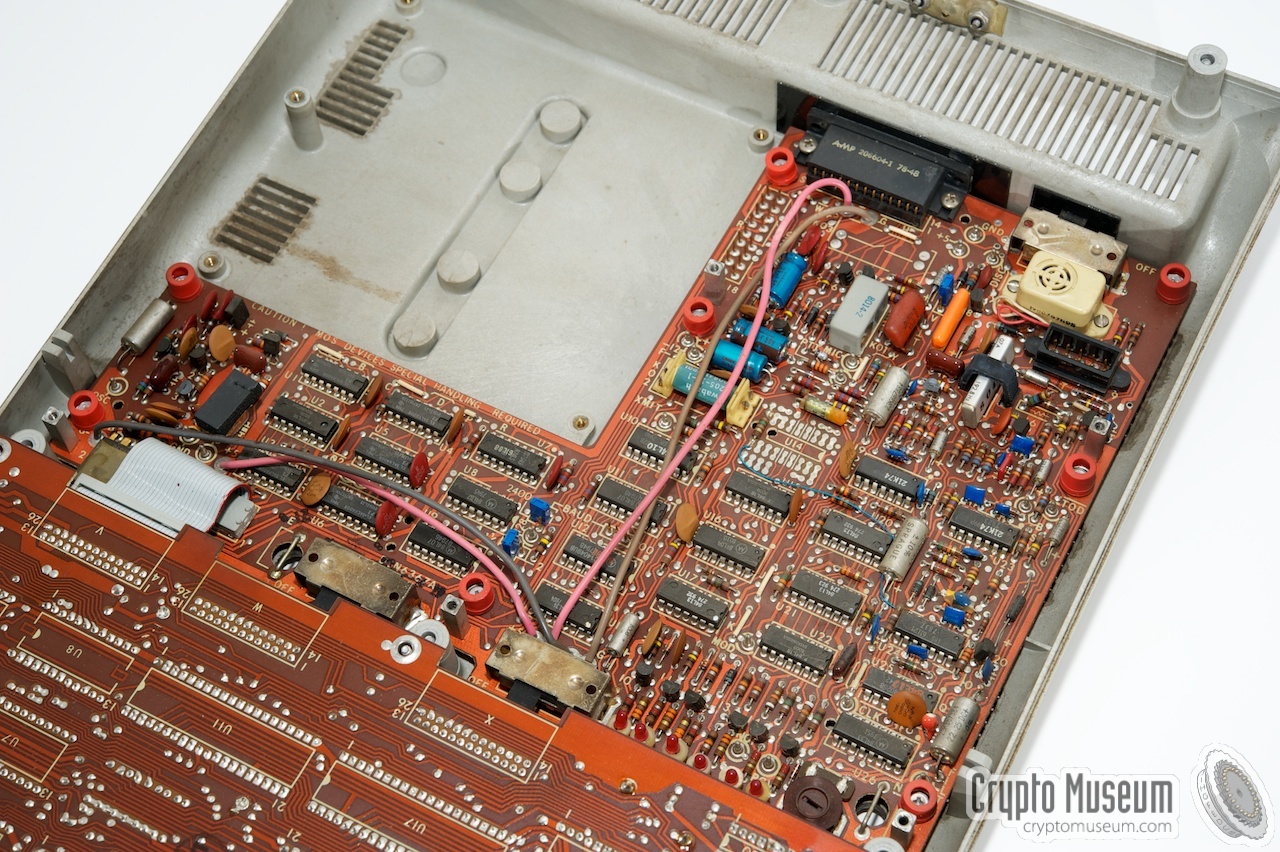
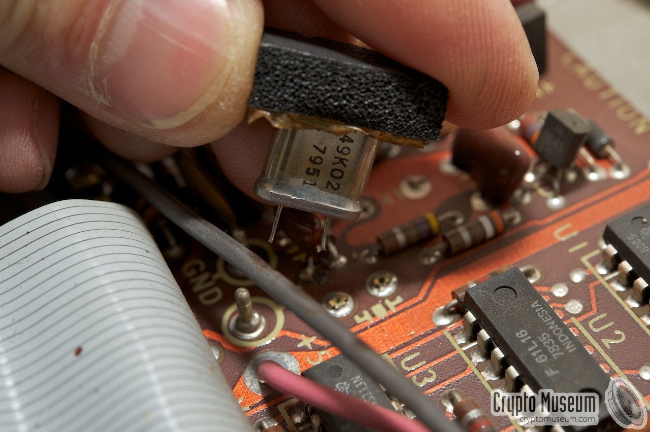
The upper board is connected to the bottom board by means of a single
flatcable at the front. The bottom board contains additional logic and the
oscillator. The crystal is socketed on the board and is held in place between
the two PCBs with a piece of foam.
|
|
|
The bottom board also contains the interface to the radio. The data-bits
are interleaved as per protocol and the baudrate can be selected
by some jumpers, although the exact baudrate is unknown at present.
The images below show the interior of the D1118-B in greater detail.
The rightmost image shows the character generator, which is mounted to the
rear of the display.
In the unit shown here, it is rather difficult to determine which components
are used, as most ICs are marked with dedicated Motorola OEM numbers.
The processor is marked 61L31.
According to [2] it is an Intel 8049 with the Motorola logo.
The three I/O chips are marked 61L32, which are in fact
Motorola-built SC67314P PIAs.
|
The data protocol used by the D1118 mobile data terminal is currently unknown,
but it is likely that it is the same MDT-4800 protocol used by Motorola's other
MDTs. It is basically an 4800 baud protocol, that uses 112 bit data packets
with bit interleaving and error-correction. It also has clock synchronisation
and frame synchronisation packets.
Please note that, apart from a rather complex method of bit-interleaving and
error-correcting, most MDTs have little or no encryption at all, although
Motorola promised their customers a secure communications system at the time.
Because Motorola tried to keep the data protocol secret, this is a typical
example of Security by Obscurity.
A full description of the MDT-4800 protocol, complete with the circuit diagram
for an interface and suitable C-code, is available from the
documentation section below.
Please note that the software is not ours and that the copyright
belongs to the various contributors. Please check the text and the source
code for their credits.
|
|
|
The Blues Brothers (1980)
|
|
|
|
The Motorola D1118 Mobile Data Terminal was featured in the movie
The Blues Brothers [4]. In the movie, the system was called S.C.M.O.D.S.,
which stands for State County Municipal Offender Data System. In the
scene below, Elwood is pulled over and his licence is checked on SCMODS:
|
After the police officer enters Elwood's licence number, the terminal
replies with the following:
BLUES, ELWOOD
ILLINOIS LICENSE: B263-1655-2187
CURRENTLY UNDER SUSPENSION
WARRANTS OUTSTANDING: PARKG. 116
MOVING VIOLATIONS: 56
ARREST DRIVER... IMPOUND VEHICLE
➤ Still from the movie
|
|
|
|
In 1998, a hobbyist [2] managed to find the most important connections on
the 25-way D-type connector at the rear of the unit. These comprise the various
voltages needed to get the unit going. The following connections are currently known:
|
- GND
- PTT (push-to-talk)
- DISC (receiver discriminator output)
-
-
-
- GND
- -12V
- +5V
-
-
-
-
-
-
- -250V
-
-
- +12V
-
- -5V
-
-
-
- GND
|
|
So, to get a surplus D1118 unit going, you would need an external power supply
unit with +/- 5V, +/- 12V and -250V. The -250V is needed for the plasma display.
When building such a power supply, beware that 250V is a dangerous voltage.
Furthermore, take care to shield the -250V from the other voltages and signals
as it can easily damage the circuitry.
|
-
Website no linger available.
|
|
|
|
Any links shown in red are currently unavailable.
If you like the information on this website, why not make a donation?
© Crypto Museum. Created: Sunday 10 February 2013. Last changed: Tuesday, 26 December 2023 - 16:54 CET.
|
 |

|
|
|
|


![D1118-B donated by Barry Wels [1]](img/301214/000/full.jpg)


![D-1118 terminal used by the ambulance service in Vienna (Austria) [5]](img/d1118_vienna_thumb.jpg "image # d1118_vienna.jpg")
![D-1118 terminal used by the ambulance service in Vienna (Austria) [5]](img/d1118_vienna.jpg)


